Hardware Connection
This document introduces what hardware you need to prepare and how to connect them in order to download AT firmware, send AT commands, and receive AT responses.
The commands supported by each series of AT firmware vary, and its compatibility with modules or chips also differs. For more information, refer to ESP-AT Firmware Differences.
If you don’t want to use the default AT pin, you can refer to the How to Set AT Port Pins document to change the pin.
What You Need
Component |
Function |
|---|---|
ESP32-C2 board |
Slave MCU. |
USB cable (connects ESP32-C2 board to the PC) |
Download/Log output connection. |
PC |
Act as Host MCU. Download firmware to Slave MCU. |
USB cable (connects the PC to the USB-to-UART converter) |
AT command/response connection. |
USB-to-UART converter |
Convert between USB signals and TTL signals. |
Jumper wires (connects the USB-to-UART converter to ESP32-C2 board) |
AT command/response connection. |
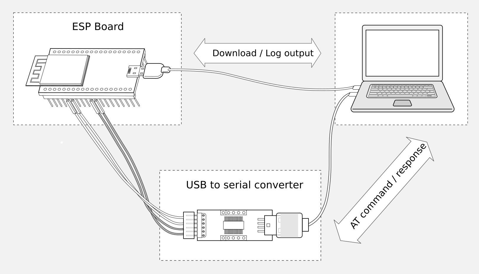
Connection of Components for ESP-AT Testing
Note:
The official default AT Binary Lists only supports 26 MHz crystal oscillator. If your crystal oscillator of ESP32-C2 is 40 MHz, please refer to Compile ESP-AT Project Locally document to compile ESP32-C2 AT firmware, and configure in the step 5:
python build.py menuconfig > Component config > Hardware Settings > Main XTAL Config > Main XTAL frequency > 40 MHz
In the above picture, four jump wires are used to connect the ESP32-C2 board and USB-to-UART converter. If you do not use hardware flow control, two wires connecting TX/RX and a simpler converter will be enough.
If you use an ESP32-C2 module (instead of a development board) and flash firmware via UART, you need to:
Reserve the U0RXD and U0TXD pins (refer to Datasheet > IO Pins)
Choose one of the following methods to enter download mode:
Reserve the strapping pins (refer to Datasheet > Boot Configurations) and enter download mode by controlling the strapping pin level
Send AT+RST=1,1 command to enter download mode
For more details, please refer to ESP32-C2 Hardware Requirements for Entering Download Mode
ESP32-C2-4MB/ESP32-C2-4MB-G2 Series
ESP32-C2-4MB/ESP32-C2-4MB-G2 series refer to the module or board that has a built-in ESP32-C2/ESP8684 chip with a 4 MB flash, such as ESP32-C2 MINI series device and ESP32-C2 WROOM series device.
ESP32-C2-4MB/ESP32-C2-4MB-G2 AT uses two UART ports: UART0 is used to download firmware and log output; UART1 is used to send AT commands and receive AT responses. Both UART0 and UART1 use 115200 baud rate for communication by default. When a 26 MHz crystal oscillator (XTAL) is used, the ROM-stage log is output via UART0 (TX: GPIO20) at 74880 baud. If the XTAL is changed to 40 MHz, the log output switches to 115200 baud.
Function of Connection |
ESP32-C2 Board or Module Pins |
Other Device Pins |
|---|---|---|
Download/Log output 1 |
|
|
AT command/response 2 |
|
|
Note 1: Connection between individual pins of the ESP32-C2 board and the PC is already established internally on the ESP32-C2 board. You only need to provide USB cable between the board and PC.
Note 2: CTS and RTS pins are required only when hardware flow control is enabled.
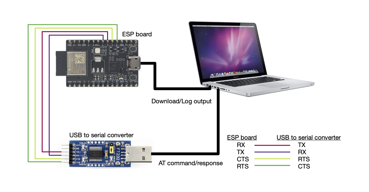
ESP32-C2-4MB/ESP32-C2-4MB-G2 Series Hardware Connection
If you want to connect your device directly with ESP32-C2 module rather than the ESP32-C2 board that integrates it, please refer to the corresponding module datasheet for details.
ESP32-C2-2MB/ESP32-C2-2MB-G2 Series
ESP32-C2-2MB/ESP32-C2-2MB-G2 series refers to the module or board that has a built-in ESP32-C2/ESP8684 chip with a 2 MB flash.
ESP32-C2-2MB/ESP32-C2-2MB-G2 AT uses two UART ports: UART0 is used to download firmware and log output; UART1 is used to send AT commands and receive AT responses. Both UART0 (GPIO8, used to output log) and UART1 use 115200 baud rate for communication by default. When a 26 MHz crystal oscillator (XTAL) is used, the ROM-stage log is output via UART0 (TX: GPIO20) at 74880 baud. If the XTAL is changed to 40 MHz, the log output switches to 115200 baud.
Function of Connection |
ESP32-C2 Board or Module Pins |
Other Device Pins |
|---|---|---|
Download/Log output 1 |
|
|
AT command/response 2 |
|
|
Log output |
|
|
Note 1: Connection between individual pins of the ESP32-C2 board and the PC is already established internally on the ESP32-C2 board. You only need to provide USB cable between the board and PC.
Note 2: CTS and RTS pins are required only when hardware flow control is enabled.
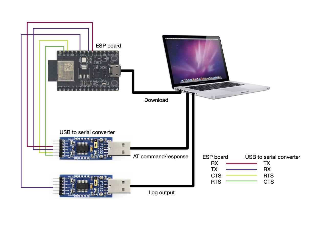
ESP32-C2-2MB/ESP32-C2-2MB-G2 Series Hardware Connection
If you want to connect your device directly with ESP32-C2 module rather than the ESP32-C2 board that integrates it, please refer to the corresponding module datasheet for details.
ESP32-C2-2MB-BLE/ESP32-C2-2MB-BLE-G2 Series
ESP32-C2-2MB-BLE/ESP32-C2-2MB-BLE-G2 series has the same hardware connection as the ESP32-C2-4MB/ESP32-C2-4MB-G2 series, with the only difference being the supported software features.
The AT firmware for this series is not released. You can choose one of the following ways to obtain the AT firmware for this series:
Refer to the documentation How to Download the Latest Temporary Version of AT Firmware from GitHub, and download the
esp32c2-2mb-ble-at/esp32c2-2mb-ble-g2-atfirmware.Compile ESP-AT Project Locally, and in the third step of the environment installation, select
Platform nameasPLATFORM_ESP32C2andModule nameasESP32-C2-2MB-BLE/ESP32-C2-2MB-BLE-G2.
ESP32-C2-2MB-NO-OTA-G2 Series
ESP32-C2-2MB-NO-OTA-G2 series has the same hardware connection as the ESP32-C2-4MB/ESP32-C2-4MB-G2 series, with the only difference being the supported software features.
The AT firmware for this series is not released. You can choose one of the following ways to obtain the AT firmware for this series:
Refer to the documentation How to Download the Latest Temporary Version of AT Firmware from GitHub, and download the
esp32c2-2mb-no-ota-g2-atfirmware.Compile ESP-AT Project Locally, and in the third step of the environment installation, select
Platform nameasPLATFORM_ESP32C2andModule nameasESP32C2-2MB-NO-OTA-G2.