ESP32-S31-Function-CoreBoard-1
This user guide will help you get started with ESP32-S31-Function-CoreBoard-1 and provides detailed information about this development board.
The ESP32-S31-Function-CoreBoard-1 is a development board for connected AIoT prototyping based on the ESP32-S31-WROOM-3 module. It supports Wi-Fi 6, IEEE 802.15.4, Bluetooth 5.4 (LE + BR/EDR), and Gigabit Ethernet; provides an onboard microphone and speaker output; routes out all key GPIOs; and supports out-of-the-box AI voice interaction evaluation.
Most of the I/O pins on the module are broken out to pin header J2 for easy interfacing.
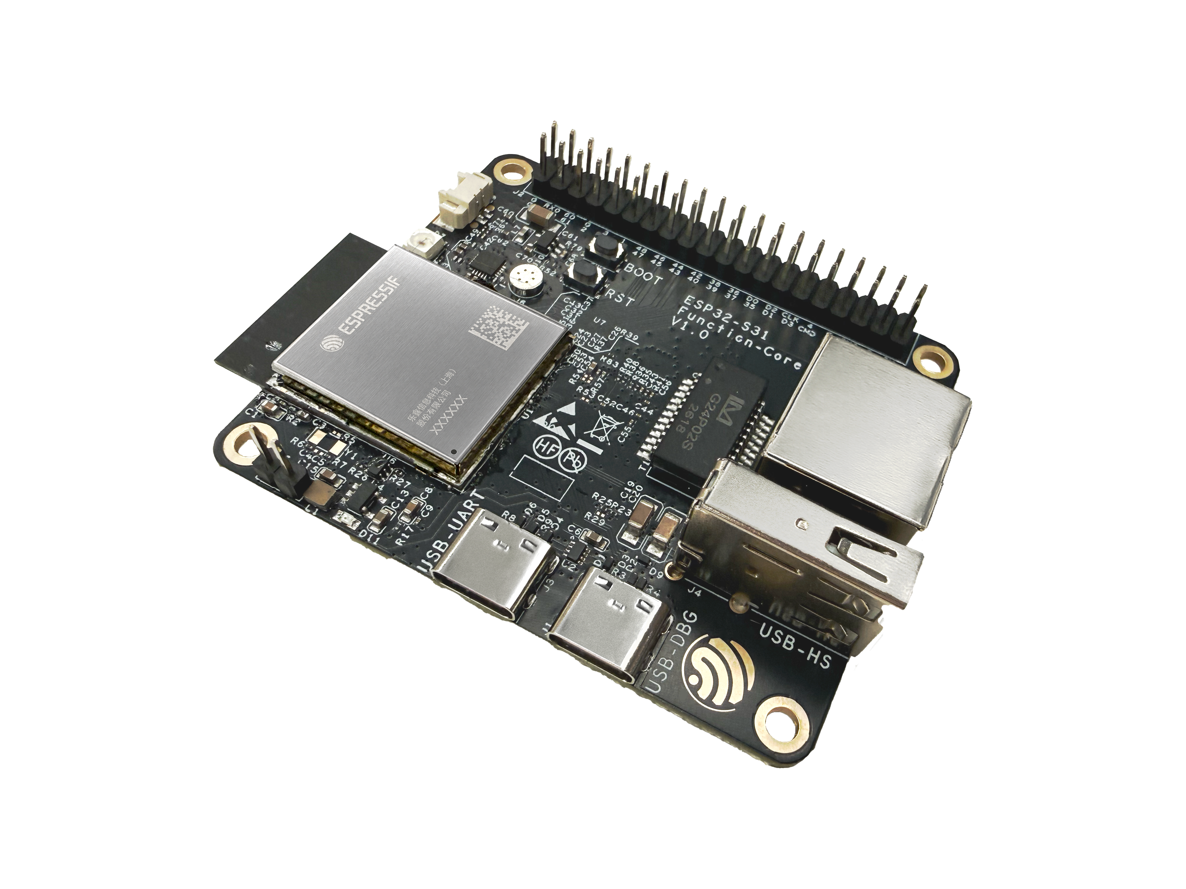
ESP32-S31-Function-CoreBoard-1 (with ESP32-S31-WROOM-3 module on board)
The document consists of the following major sections:
Getting Started: Overview of ESP32-S31-Function-CoreBoard-1 and hardware/software setup instructions to get started.
Hardware Reference: More detailed information about the ESP32-S31-Function-CoreBoard-1’s hardware.
Hardware Revision Details: Information about revision history, known issues, and links to user guides for previous versions (if any).
Related Documents: Links to related documentation.
Getting Started
This section briefly introduces ESP32-S31-Function-CoreBoard-1 and explains how to perform the initial hardware setup and how to flash firmware onto the board.
Description of Components
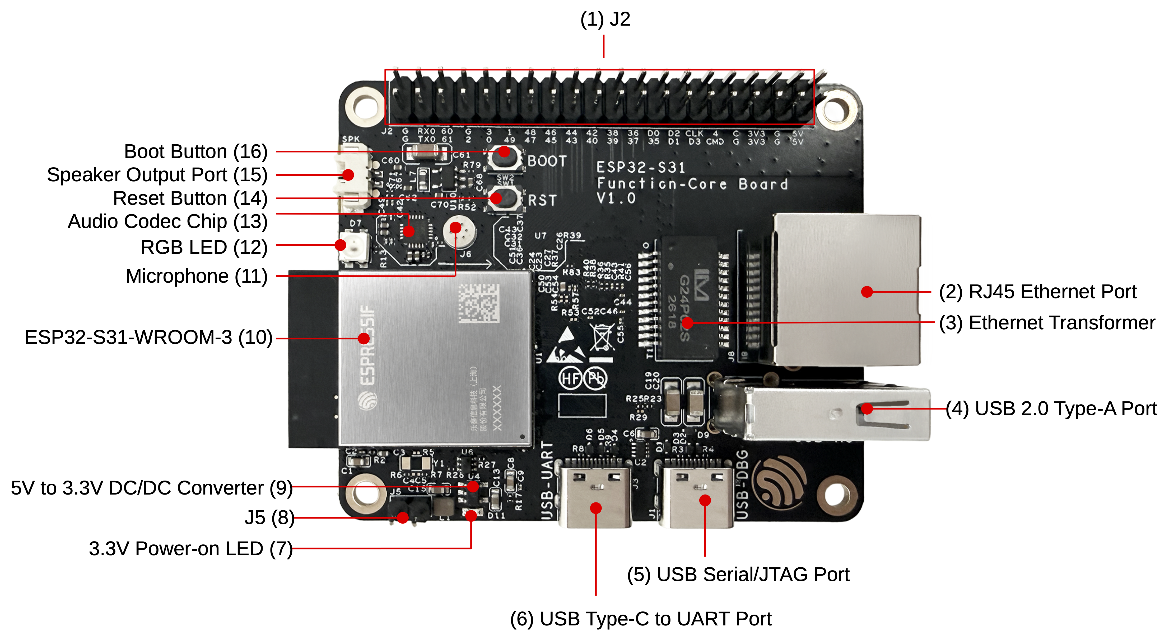
ESP32-S31-Function-CoreBoard-1 - front (click to enlarge)
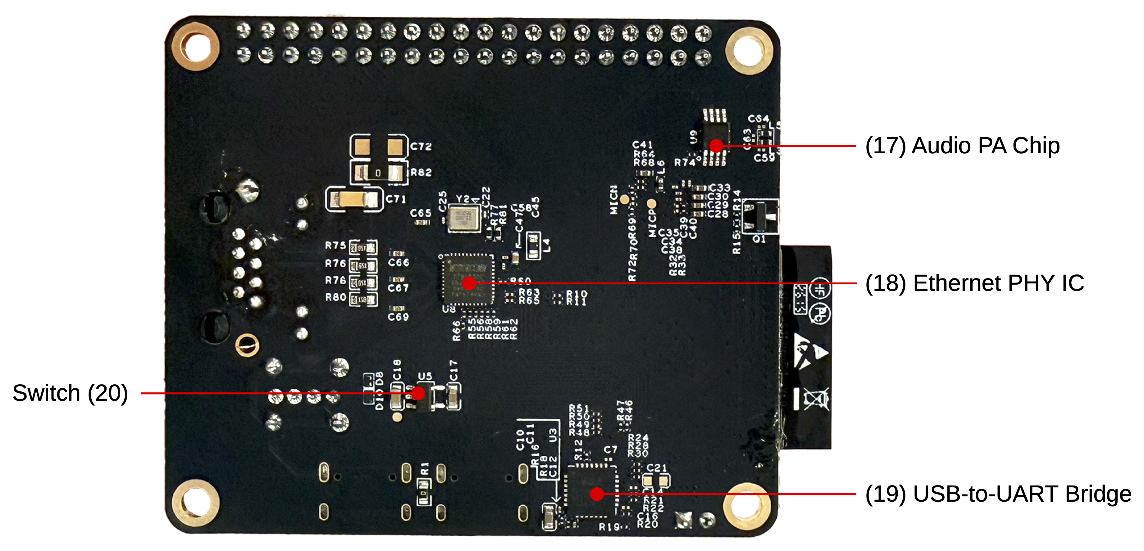
ESP32-S31-Function-CoreBoard-1 - back (click to enlarge)
The following table lists the key components on the front and back of the board in clockwise order.
No. |
Key Component |
Description |
|---|---|---|
1 |
J2 |
All available GPIO pins are broken out to header J2 for easy interfacing. For more details, see Header Block. |
2 |
RJ45 Ethernet Port |
An Ethernet port supporting 10/100/1000 Mbps auto-negotiation. |
3 |
Ethernet Transformer |
Transformer module for the RJ45 Ethernet port. |
4 |
USB 2.0 Type-A Port |
The USB 2.0 Type-A port is connected to the USB 2.0 OTG High-Speed interface of the ESP32-S31, compliant with the USB 2.0 specification. When communicating with other devices via this port, the ESP32-S31 acts as a USB host, providing up to 500 mA of current. |
5 |
USB Serial/JTAG Port |
USB Type-C port that supports USB 2.0 Full-Speed data rate. It can be used to supply power to the board, flash firmware to the ESP32-S31 chip, communicate with the chip via the USB protocol, and perform JTAG debugging. |
6 |
USB Type-C to UART Port |
Used for power supply to the board, flashing applications to the chip, as well as communication with the ESP32-S31 chip via the on-board USB-to-UART bridge. |
7 |
3.3 V Power-on LED |
Turns on when the board is connected to USB power. |
8 |
J5 |
Used for current measurement. See details in section Current Measurement. |
9 |
5 V to 3.3 V DC/DC Converter |
Power regulator that converts a 5 V supply into a 3.3 V output. |
10 |
ESP32-S31-WROOM-3 |
ESP32-S31-WROOM-3 integrates the ESP32-S31 chip and supports Bluetooth 5.4 (LE) and IEEE 802.15.4 (Zigbee/Thread/Matter), suitable for a wide range of low-power IoT applications. |
No. |
Key Component |
Description |
|---|---|---|
11 |
Microphone |
Onboard microphone connected to the interface of the audio codec chip. |
12 |
RGB LED |
Addressable RGB LED, driven by GPIO60. |
13 |
Audio Codec Chip |
ES8311 is a low-power mono audio codec. It includes a single-channel ADC, a single-channel DAC, a low-noise pre-amplifier, a headphone driver, digital sound effects, analog mixing, and gain functions. It interfaces with the ESP32-S31 chip over I2S and I2C buses to provide hardware audio processing independent of the audio application. |
14 |
Reset Button |
Press this button to reset the ESP32-S31. |
15 |
Speaker Output Port |
This port is used to connect a speaker. The maximum output power can drive a 4 Ω, 3 W speaker. The pin spacing is 1.25 mm (0.08”). |
16 |
Boot Button |
Download button. Holding down Boot and then pressing Reset initiates Firmware Download mode for downloading firmware through the UART port or USB Serial/JTAG port. |
17 |
Audio PA Chip |
NS4150B is an EMI-compliant, 3 W mono Class D audio power amplifier that amplifies audio signals from the audio codec chip to drive speakers. |
18 |
Ethernet PHY IC |
Ethernet PHY chip connected to the ESP32-S31 RGMII interface and the RJ45 Ethernet port. |
19 |
USB-to-UART Bridge |
Single-chip USB-to-UART bridge that works with the USB Type-C to UART Port for board power, firmware flashing, and serial communication with the ESP32-S31 chip. |
20 |
Switch |
TPS2051C is a USB power switch that provides a 500 mA output current limit. |
Start Application Development
Before powering up your ESP32-S31-Function-CoreBoard-1, please make sure that it is in good condition with no obvious sign of damage.
Required Hardware
ESP32-S31-Function-CoreBoard-1
USB 2.0 cable (USB-A to Type-C)
Computer running Windows, Linux, or macOS
Note
Be sure to use a good quality USB cable. Some cables are for charging only and do not provide the needed data lines and will not work for programming this board.
Hardware Setup
Connect the ESP32-S31-Function-CoreBoard-1 to your computer using a USB cable. The board can be powered through any of the USB Type-C ports.
Software Setup
Please proceed to ESP-IDF Get Started, which will help you set up the development environment quickly and then flash an application onto your board.
Note
The board uses a USB port to communicate with the computer. Most operating systems (Windows, Linux, macOS) come with the required drivers pre-installed and the board is recognized automatically once plugged in. If the device cannot be recognized or a serial connection cannot be established, refer to Establish Serial Connection with ESP32-S31 for detailed driver installation steps.
Espressif provides board peripheral management components for many development boards to help you initialize and use key onboard peripherals such as LCD, audio codec, keys, and LEDs more easily and efficiently. Please visit the esp_board_manager component in ESP Component Registry for support coverage.
Other Development Framework Options
In addition to ESP-IDF, this board supports the following frameworks and options for different user needs:
Espressif Bluetooth LE ecosystem: Develop Bluetooth LE applications using solutions such as ESP-BLE-MESH and ESP-BLE-AUDIO to accelerate time-to-market and mass production.
ESP-GMF: Espressif general multimedia framework with audio/video processing components for multimedia applications.
Wi-Fi audio/video examples: Sample Wi-Fi audio and video applications to help integrate multimedia features into your project.
Bluetooth audio: Unified Bluetooth audio APIs supporting Bluetooth Classic and LE Audio.
ESP-Matter: Build Matter and Thread devices suited to low-power and battery-powered scenarios.
Contents and Packaging
Retail Orders
If you order a few samples, each ESP32-S31-Function-CoreBoard-1 comes in an individual package in either an antistatic bag or any other packaging depending on your retailer.
For retail orders, please go to Get Samples.
Wholesale Orders
If you order in bulk, the boards come in large cardboard boxes.
For wholesale orders, please go to Contact Us.
Hardware Reference
Block Diagram
The main components of ESP32-S31-Function-CoreBoard-1 and their interconnections are shown in the block diagram below.
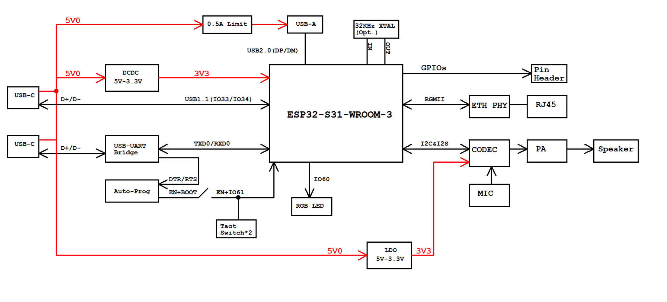
ESP32-S31-Function-CoreBoard-1 block diagram (click to enlarge)
Power Supply Options
The board can be powered using one of the following options:
Via the USB-to-UART port or the ESP32-S31 USB port (either port or both), default method (recommended)
5V and G (GND) pin headers
Current Measurement
The J5 headers on ESP32-S31-Function-CoreBoard-1 (see J5 in Figure ESP32-S31-Function-CoreBoard-1 - front (click to enlarge)) can be used for measuring the current drawn by the ESP32-S31-WROOM-3 module:
Remove the jumper: Power supply between the module and peripherals on the board is cut off. To measure the module’s current, connect an ammeter in series via the J5 headers.
Apply the jumper (factory default): Restore the board’s normal functionality.
Header Block
The table below provides the Name and Function of pin header J2. The pin names are shown in Figure ESP32-S31-Function-CoreBoard-1 - front (click to enlarge). The numbering is the same as in the ESP32-S31-Function-CoreBoard-1 schematic (PDF).
J2
No. |
Name |
Type [1] |
Function |
|---|---|---|---|
1 |
G |
G |
Ground |
2 |
G |
G |
Ground |
3 |
TX0 |
I/O/T |
U0TXD, GPIO58 |
4 |
RXD |
I/O/T |
U0RXD, GPIO59 |
5 |
61 |
I/O/T |
BOOT, GPIO61 |
6 |
60 |
I/O/T |
GPIO60 [2] |
7 |
2 |
I/O/T |
GPIO2 |
8 |
G |
G |
Ground |
9 |
0 |
I/O/T |
GPIO0 |
10 |
3 |
I/O/T |
GPIO3 |
11 |
49 |
I/O/T |
GPIO49 |
12 |
1 |
I/O/T |
GPIO1 |
13 |
47 |
I/O/T |
GPIO47 |
14 |
48 |
I/O/T |
GPIO48 |
15 |
45 |
I/O/T |
GPIO45 |
16 |
46 |
I/O/T |
GPIO46 |
17 |
43 |
I/O/T |
GPIO43 |
18 |
44 |
I/O/T |
GPIO44 |
19 |
40 |
I/O/T |
GPIO40 |
20 |
42 |
I/O/T |
GPIO42 |
21 |
39 |
I/O/T |
GPIO39 |
22 |
38 |
I/O/T |
GPIO38 |
23 |
37 |
I/O/T |
GPIO37 |
24 |
36 |
I/O/T |
GPIO36 |
25 |
35 |
I/O/T |
GPIO35 |
26 |
D0 |
I/O/T |
SDIO_DATA0, GPIO20 |
27 |
D1 |
I/O/T |
SDIO_DATA1, GPIO21 |
28 |
D2 |
I/O/T |
SDIO_DATA2, GPIO22 |
29 |
D3 |
I/O/T |
SDIO_DATA3, GPIO23 |
30 |
CLK |
I/O/T |
SDIO_CLK, GPIO24 |
31 |
CMD |
I/O/T |
SDIO_CMD, GPIO25 |
32 |
4 |
I/O/T |
GPIO4 |
33 |
G |
G |
Ground |
34 |
G |
G |
Ground |
35 |
3V3 |
P |
3.3 V power supply |
36 |
3V3 |
P |
3.3 V power supply |
37 |
G |
G |
Ground |
38 |
G |
G |
Ground |
39 |
5V |
P |
5 V power supply |
40 |
5V |
P |
5 V power supply |
Hardware Revision Details
No previous versions available.