ESP32-S31-Korvo-1 V1.1
This user guide will help you get started with ESP32-S31-Korvo-1 V1.1 and provides detailed information about this development board.
The ESP32-S31-Korvo-1 V1.1 is a multimedia development board based on the ESP32-S31-WROOM-3 module for smart audio and HMI applications. It features a dual-microphone array, speaker output, and a microSD card slot; supports speech recognition and voice wake-up; and can connect to a 4.3-inch LCD subboard and DVP camera.
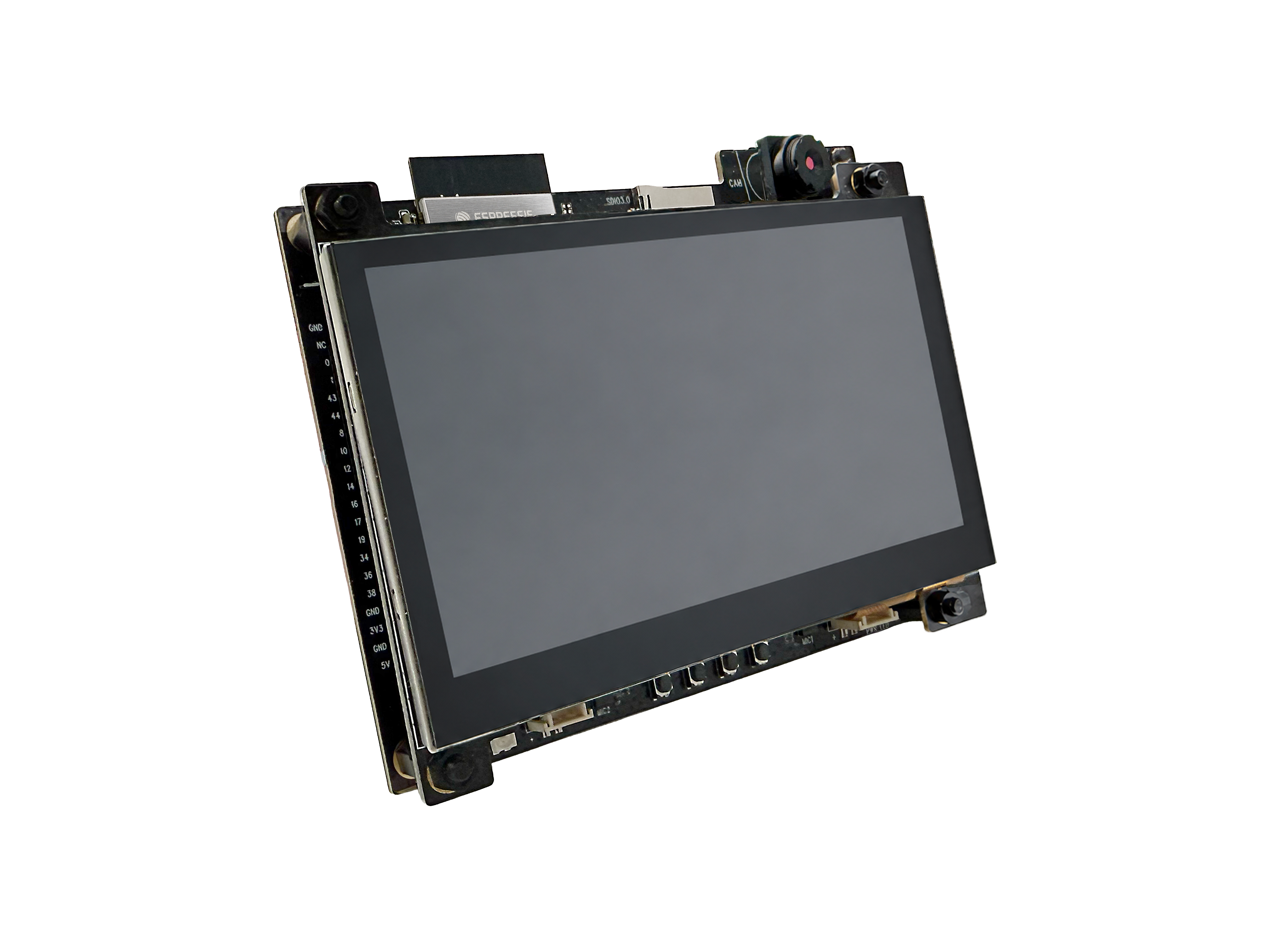
ESP32-S31-Korvo-1 V1.1 (with ESP32-S31-WROOM-3 module on board)
The document consists of the following major sections:
Getting Started: Overview of ESP32-S31-Korvo-1 V1.1 and hardware/software setup instructions to get started.
Hardware Reference: More detailed information about the ESP32-S31-Korvo-1 V1.1 hardware.
Hardware Revision Details: Information about revision history, known issues, and links to user guides for previous versions.
Related Documents: Links to related documentation.
Getting Started
This section briefly introduces ESP32-S31-Korvo-1 V1.1 and explains how to perform the initial hardware setup and how to flash firmware onto the board.
Description of Components
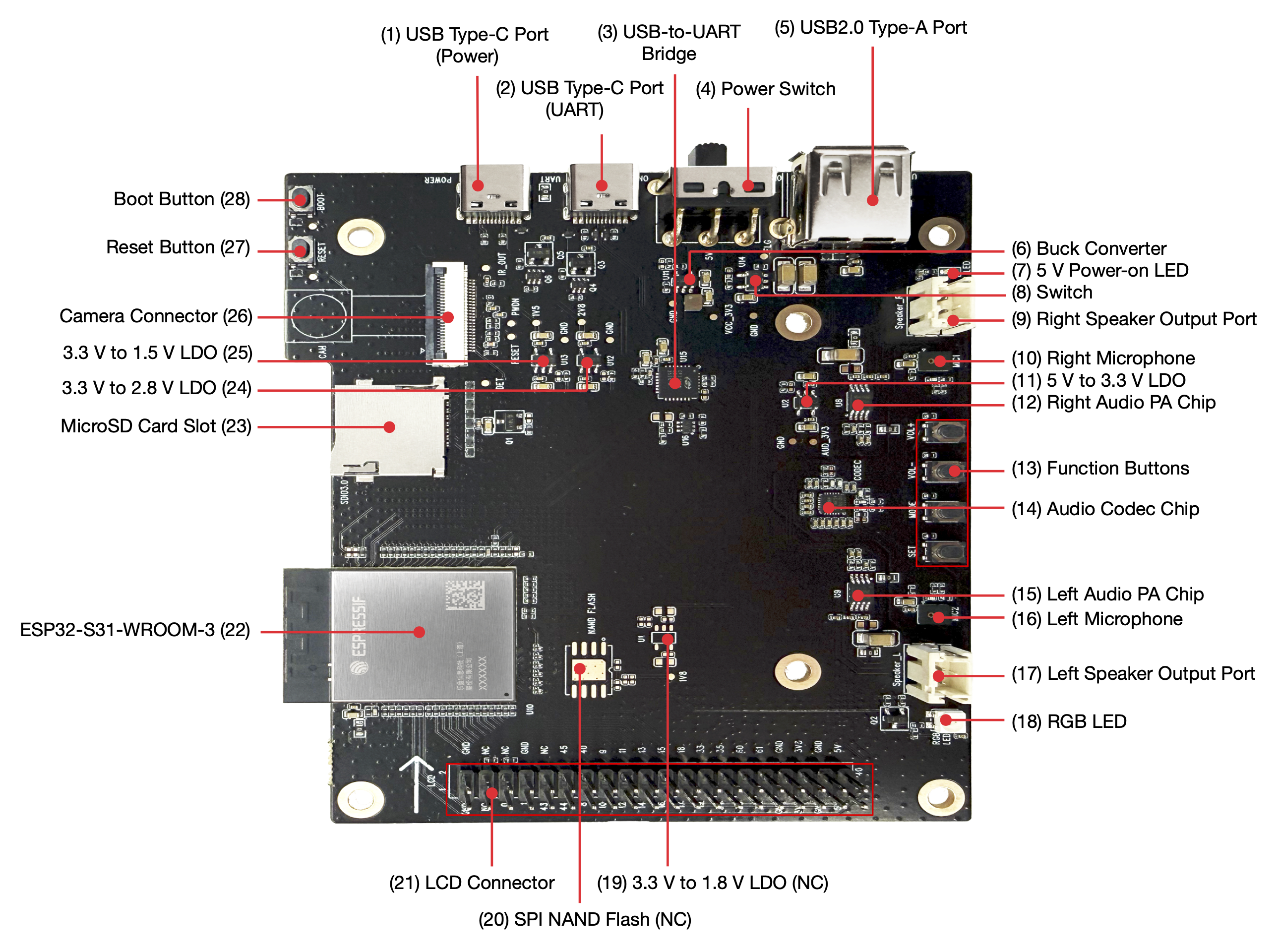
ESP32-S31-Korvo-1 V1.1 (click to enlarge)
The following list describes the key components on the board in a clockwise direction.
No. |
Component |
Description |
|---|---|---|
1 |
USB Type-C Port (Power) |
Power input only; no data communication. |
2 |
USB Type-C Port (UART) |
Can power the board, flash firmware to the chip, and communicate with the ESP32-S31 via the onboard USB-to-UART bridge. |
3 |
USB-to-UART Bridge |
Single-chip USB-to-UART bridge supporting up to 3 Mbps. |
4 |
Power Switch |
Slide toward ON to apply 5 V power; slide away from ON to disconnect 5 V power. |
5 |
USB 2.0 Type-A Port |
Connected to the ESP32-S31 USB 2.0 OTG High-Speed interface and supports the USB 2.0 standard. When used for USB communication, ESP32-S31 acts as a USB Host connected to downstream USB devices, providing up to 500 mA output current. |
6 |
Buck Converter |
Buck DC-DC converter for 3.3 V system power. |
7 |
5 V Power-on LED |
Lights when USB power is connected to the board. |
8 |
Switch |
TPS2051C USB power switch with 500 mA current limit. |
9 |
Right Speaker Output Port |
Right-channel speaker output; can drive a 4 Ω, 3 W speaker. The pin spacing is 2.00 mm (0.08”). |
10 |
Right Microphone |
Onboard right analog microphone routed to the audio codec. |
11 |
5 V to 3.3 V LDO |
Converts 5 V to 3.3 V for the audio circuitry. |
12 |
Right Audio PA Chip |
NS4150B low-EMI 3 W mono class-D amplifier driving the right speaker from the codec output. |
13 |
Function Buttons |
Four buttons: PLAY, SET, VOL-, and VOL+, connected to ESP32-S31-WROOM-3 for UI control and audio application testing via dedicated APIs. |
14 |
Audio Codec Chip |
ES8389 low-power stereo codec with dual ADC/DAC, low-noise preamp, headphone driver, digital effects, analog mixing, and gain control. Connected to the ESP32-S31 over I2S and I2C for hardware audio processing independent of application software. |
15 |
Left Audio PA Chip |
NS4150B low-EMI 3 W mono class-D amplifier driving the left speaker from the codec output. |
16 |
Left Microphone |
Onboard left analog microphone routed to the audio codec. |
17 |
Left Speaker Output Port |
Left-channel speaker output; can drive a 4 Ω, 3 W speaker. The pin spacing is 2.00 mm (0.08”). |
18 |
RGB LED |
Addressable RGB LED driven by GPIO8. |
No. |
Component |
Description |
|---|---|---|
19 |
3.3 V to 1.8 V LDO (NC) |
Converts 3.3 V to 1.8 V for 1.8 V SPI NAND flash. Not populated by default (NC). |
20 |
SPI NAND Flash (NC) |
Quad SPI NAND flash sharing ESP32-S31-WROOM-3 signals with the microSD interface. Not populated by default (NC). |
21 |
LCD Connector |
Connector for the LCD subboard. |
22 |
ESP32-S31-WROOM-3 |
ESP32-S31-WROOM-3 is a general-purpose module supporting 2.4 GHz Wi-Fi 6, Bluetooth 5.4, Bluetooth Classic, and IEEE 802.15.4 (Zigbee 3.0 and Thread 1.4). The module integrates ESP32-S31, 16 MB SPI flash, and 16 MB PSRAM, and uses an onboard PCB antenna. |
23 |
microSD Card Slot |
Supports 4-bit microSD for audio storage and playback. SDIO 3.0 capable. |
24 |
3.3 V to 2.8 V LDO |
Converts 3.3 V to 2.8 V for the external camera module. |
25 |
3.3 V to 1.5 V LDO |
Converts 3.3 V to 1.5 V for the external camera module. |
26 |
Camera Connector |
Connector for an external camera module for image transfer. |
27 |
Reset Button |
System reset. |
28 |
Boot Button |
Firmware download: hold Boot, press and release Reset to enter download mode; flash over the serial port. |
Development Board Accessories
The ESP32-S31-Korvo-1 V1.1 package may include the following optional accessories. The main board and accessories can also be purchased separately. Available accessories include:
LCD subboard: ESP32-S3-LCD-EV-Board-SUB3
OV3660 camera module
Start Application Development
Before powering up the board, please make sure that it is in good condition with no obvious sign of damage.
Required Hardware
ESP32-S31-Korvo-1 V1.1
One or two speakers
Two USB 2.0 cables (Standard-A to Type-C)
Computer running Windows, Linux, or macOS
Note
Be sure to use a good-quality USB cable. Some cables are for charging only and do not provide the needed data lines nor work for programming the board.
Optional Hardware
microSD card
Hardware Setup
Connect one or two speakers to the speaker output port(s).
Plug in two USB cables from the PC to both USB ports on the board.
Turn on the power switch.
The red power LED should light.
Software Setup
Please proceed to ESP-IDF Get Started, which will help you set up the development environment quickly and then flash an application onto your board.
Note
The board uses USB ports to communicate with the computer. Most operating systems (Windows, Linux, macOS) come with the required drivers pre-installed and the board is recognized automatically once plugged in. If the device cannot be recognized or a serial connection cannot be established, refer to Establish Serial Connection with ESP32-S31 for detailed driver installation steps.
Espressif provides board peripheral management components for many development boards to help you initialize and use key onboard peripherals such as LCD, audio codec, keys, and LEDs more easily and efficiently. Please visit the esp_board_manager component on the ESP Component Registry for support coverage.
Other Development Framework Options
In addition to ESP-IDF, this board supports the following frameworks and options for different user needs:
Espressif Bluetooth LE ecosystem: Develop Bluetooth LE applications using solutions such as ESP-BLE-MESH and ESP-BLE-AUDIO to accelerate time-to-market and mass production.
ESP-Brookesia: Human-machine interaction framework for AIoT devices for graphical UI and smart display applications.
ESP-GMF: Espressif general multimedia framework with audio/video processing components for multimedia applications.
Bluetooth audio: Unified Bluetooth audio APIs supporting Bluetooth Classic and LE Audio.
ESP Video Components: Camera, video streaming, and video processing components for image capture and video applications.
ESP-Matter: Build Matter and Thread devices suited to low-power and battery-powered scenarios.
Contents and Packaging
Retail Orders
If you order a few samples, each board comes in an individual package in either an antistatic bag or any other packaging depending on your retailer.
For retail orders, please go to Get Samples.
Wholesale Orders
If you order in bulk, the boards come in large cardboard boxes.
For wholesale orders, please go to Contact Us.
Hardware Reference
Block Diagram
The main components of ESP32-S31-Korvo-1 V1.1 and their interconnections are shown in the block diagram below.
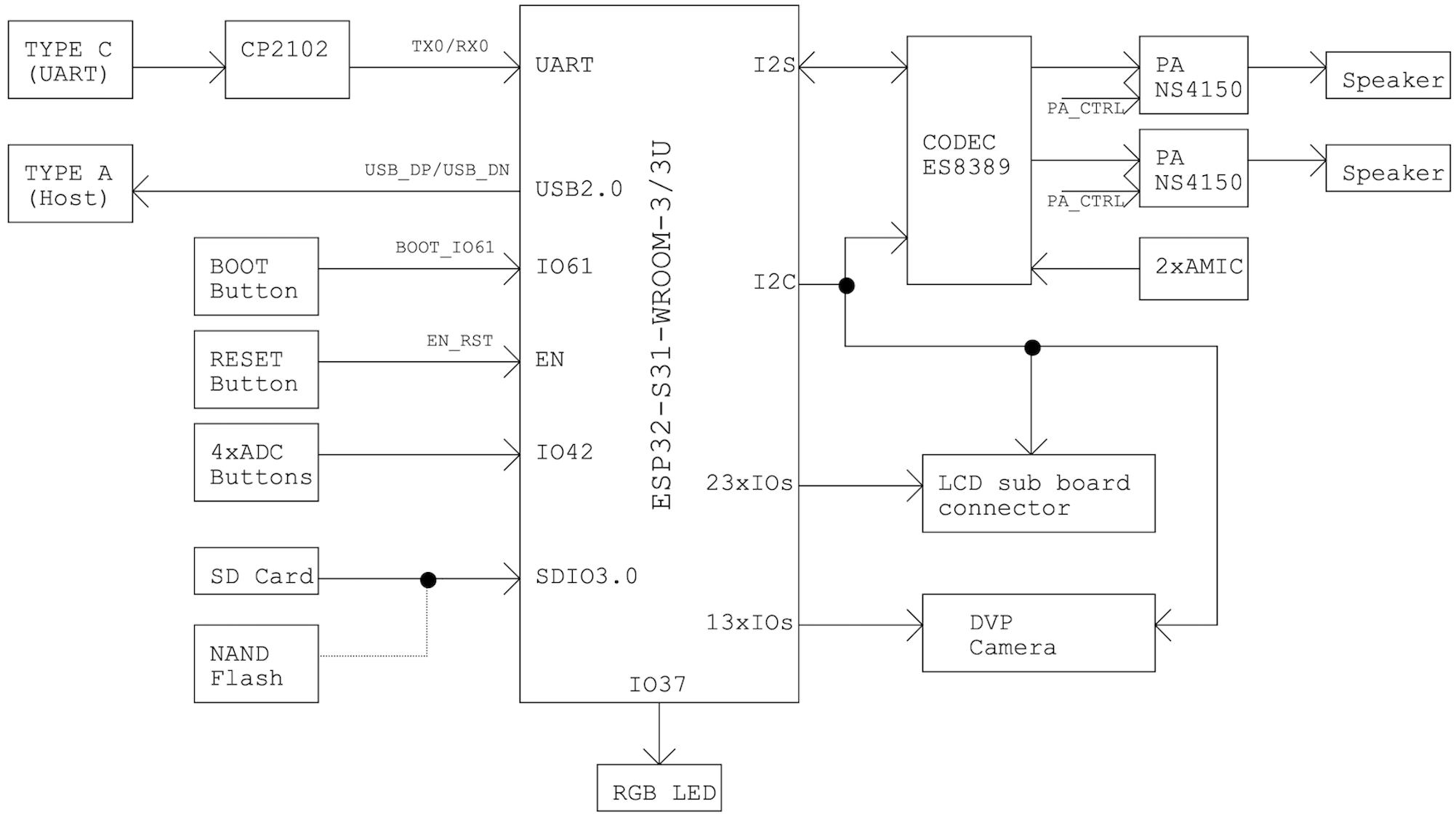
ESP32-S31-Korvo-1 V1.1 electrical block diagram (click to enlarge)
Power Supply Description
USB Power
Both USB Type-C ports can power the board: the Power port is power-only, while the UART port can supply power and carry data. When driving high-power speakers and using the USB Type-A port to power external devices at the same time, ensure the total input current to the board meets 3 A. Use a dedicated cable for USB power delivery, separate from the USB cable used for flashing applications.
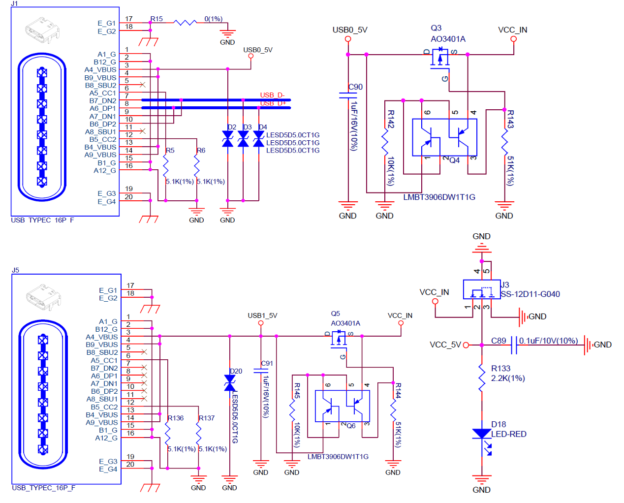
ESP32-S31-Korvo-1 V1.1 - USB power supply (click to enlarge)
Separate Audio Power
ESP32-S31-Korvo-1 V1.1 provides independent power supplies for audio components to reduce digital noise in audio signals and improve overall performance.
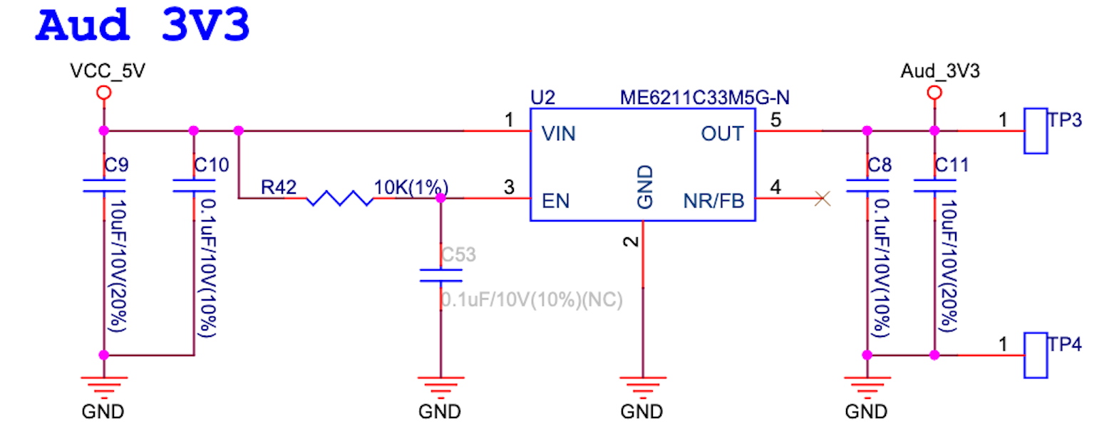
ESP32-S31-Korvo-1 V1.1 - audio power supply (click to enlarge)
ES8389 Audio Codec Notes
ESP32-S31-Korvo-1 V1.1 uses the ES8389 audio codec. When transferring audio data with the SoC, note the following:
Both DAC and ADC signals must be sent to the SoC in TDM (Time Division Multiplexing) format.
Pin 4 (MCLK) of the ES8389 can be muxed to TDMIN via register configuration.

ESP32-S31-Korvo-1 V1.1 - ES8389 audio codec schematic (click to enlarge)
microSD Card and SPI NAND Flash
The microSD card and SPI NAND flash functions share GPIO20–GPIO25 on the ESP32-S31-WROOM-3 module. The board uses the microSD card function by default. To switch to the SPI NAND flash function, perform hardware rework: remove R7, R65, R66, R67, R68, and R69, and populate R22, R23, R1, R2, R3, R4, C6, R20, and U4. Note that ESP32-S31 supports both 1.8 V and 3.3 V NAND flash. For 1.8 V NAND flash, you must also populate R134, C66, C80, R100, U1, C82, and C67; for 3.3 V NAND flash, populate R135.
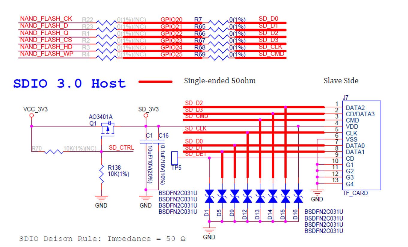
ESP32-S31-Korvo-1 V1.1 - microSD card function (click to enlarge)
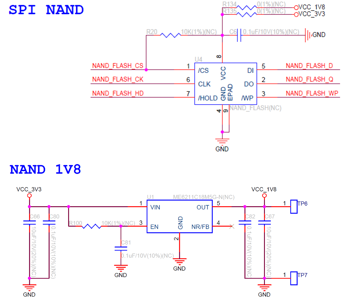
ESP32-S31-Korvo-1 V1.1 - SPI NAND flash function (click to enlarge)
Pin Assignment Table
The table below lists ESP32-S31-WROOM-3 module pin assignments to onboard functions.
Pin [1] |
Name |
SDMMC |
SPI NAND |
I2S |
I2C |
RGB LCD |
BOOTMODE |
UART0 |
Other |
DVP camera |
|---|---|---|---|---|---|---|---|---|---|---|
6 |
GPIO2 |
I2S_MCLK |
||||||||
7 |
GPIO3 |
I2S_SCLK |
||||||||
8 |
GPIO0 |
I2C_SDA |
||||||||
9 |
GPIO1 |
I2C_SCL |
||||||||
10 |
GPIO4 |
I2S_LRCLK |
||||||||
11 |
GPIO5 |
I2S_DSIN |
||||||||
12 |
GPIO6 |
I2S_SDOUT |
||||||||
13 |
GPIO7 |
PA_CTRL |
||||||||
14 |
GPIO8 |
DB0(B3) |
||||||||
15 |
GPIO9 |
DB1(B4) |
||||||||
16 |
GPIO10 |
DB2(B5) |
||||||||
17 |
GPIO11 |
DB3(B6) |
||||||||
18 |
GPIO12 |
DB4(B7) |
||||||||
19 |
GPIO13 |
DB5(G2) |
||||||||
20 |
GPIO14 |
DB6(G3) |
||||||||
21 |
GPIO15 |
DB7(G4) |
||||||||
22 |
GPIO16 |
DB8(G5) |
||||||||
23 |
GPIO17 |
DB9(G6) |
||||||||
24 |
GPIO18 |
DB10(G7) |
||||||||
25 |
GPIO19 |
DB11(R3) |
||||||||
27 |
GPIO20 |
SDIO_DATA0 |
SPI2_CLK(NC) |
|||||||
28 |
GPIO21 |
SDIO_DATA1 |
SPI2_D(NC) |
|||||||
29 |
GPIO22 |
SDIO_DATA2 |
SPI2_Q(NC) |
|||||||
30 |
GPIO23 |
SDIO_DATA3 |
SPI2_CS(NC) |
|||||||
31 |
GPIO24 |
SDIO_CLK |
SPI2_HOLD(NC) |
|||||||
32 |
GPIO25 |
SDIO_CMD |
SPI2_WP(NC) |
|||||||
40 |
USB_DP |
USB2.0_DP |
||||||||
41 |
USB_DM |
USB2.0_DM |
||||||||
42 |
GPIO33 |
DB12(R4) |
||||||||
43 |
GPIO34 |
DB13(R5) |
||||||||
44 |
GPIO35 |
DB14(R6) |
||||||||
45 |
GPIO36 |
DB15(R7) |
||||||||
46 |
GPIO37 |
WS2812_CTRL |
||||||||
49 |
GPIO38 |
LCD_CS |
Boot Mode 0 |
GM_FK |
||||||
50 |
GPIO39 |
Boot Mode 1 |
SD_CTRL |
|||||||
51 |
GPIO40 |
LCD_PCLK |
Boot Mode 2 |
|||||||
52 |
GPIO42 |
ADC BUTTON |
||||||||
53 |
GPIO43 |
LCD_H_EN |
||||||||
54 |
GPIO44 |
LCD_H_SYNC |
||||||||
55 |
GPIO45 |
LCD_V_SYNC |
||||||||
56 |
GPIO46 |
CAM_D0 |
||||||||
57 |
GPIO47 |
CAM_D1 |
||||||||
58 |
GPIO48 |
CAM_D2 |
||||||||
59 |
GPIO49 |
CAM_D3 |
||||||||
60 |
GPIO50 |
CAM_D4 |
||||||||
61 |
GPIO51 |
CAM_D5 |
||||||||
62 |
GPIO52 |
CAM_D6 |
||||||||
63 |
GPIO53 |
CAM_D7 |
||||||||
64 |
GPIO54 |
CAM_PCLK |
||||||||
65 |
GPIO55 |
CAM_XCLK |
||||||||
66 |
GPIO56 |
CAM_V_SYNC |
||||||||
67 |
GPIO57 |
CAM_H_SYNC |
||||||||
68 |
GPIO58 |
U0TXD |
||||||||
69 |
GPIO59 |
U0RXD |
||||||||
70 |
GPIO60 |
LCD_MOSI |
Boot Mode 3 |
|||||||
71 |
GPIO61 |
LCD_SCK |
Boot Mode 4 |
Hardware Setup Options
Automatic Download
There are two ways to put the ESP development board into download mode:
Manually press the Boot and RST buttons, then release RST first and Boot afterwards.
Let software perform automatic download using the serial port DTR and RTS signals to control EN and IO0. For details, see the ESP32-S31-Korvo-1 V1.1 schematic (PDF).
Hardware Revision Details
ESP32-S31-Korvo-1 V1.1:
Matte black solder mask; larger PCB footprint; LCD subboard stacks on top of the main board when assembled. GPIO mapping is unchanged from V1.0.
ESP32-S31-Korvo-1 V1.0:
First revision with green solder mask; LCD subboard extended beyond the board edge so onboard functions remained exposed for debugging.