ESP-Module-Prog-1(R)
This user guide will help you get started with ESP-Module-Prog-1(R) and provide in-depth information of this board.
ESP-Module-Prog-1 and ESP-Module-Prog-1R (R stands for WROVER) are two flashing mainboards produced by Espressif. These mainboards allow you to flash modules without the need for soldering to the power supply and signal lines. They can be used as standalone devices or in combination with a subboard. Espressif supports two subboards: ESP-Module-Prog-SUB-02 and ESP-Module-Prog-SUB-01&04, which cannot be used independently and must be used in conjunction with any of the above-mentioned mainboards.
This user guide focuses on ESP-Module-Prog-1(R) Mainboard. For detailed information about the subboards, please click the links below and check the corresponding user guides.
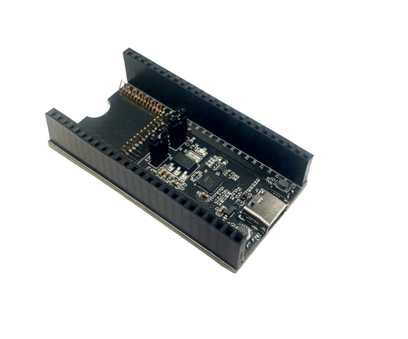
ESP-Module-Prog-1
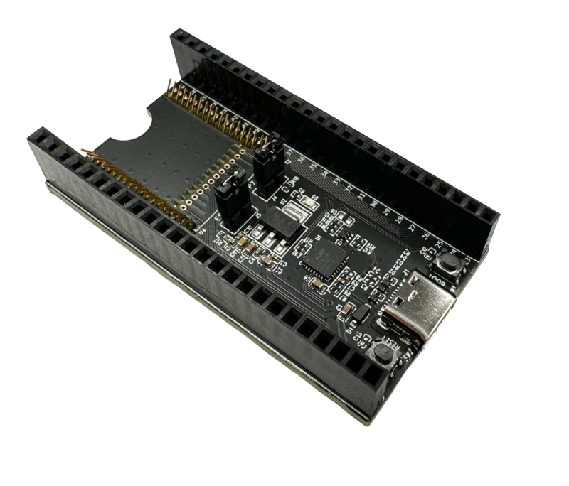
ESP-Module-Prog-1R
This user guide consists of the following sections:
Board Overview: Overview of the board hardware/software.
Start Application Development: How to set up hardware/software to develop applications.
Hardware Reference: More detailed information about the board’s hardware.
Sample Request: How to get a sample board.
Related Documents: Links to related documentation.
Board Overview
ESP-Module-Prog-1(R) is an Espressif flashing mainboard designed specifically for modules. With a module mounted, it can also be used as a mini development board like ESP32-DevKitC. The only difference between ESP-Module-Prog-1 and ESP-Module-Prog-1R lies in the layout of the spring pins, which are used to fit different modules.
Mainboard |
Fitting Module |
|---|---|
ESP-Module-Prog-1 |
|
ESP-Module-Prog-1R: |
|
For information about the above modules, please refer to Espressif Series Modules.
Description of Components
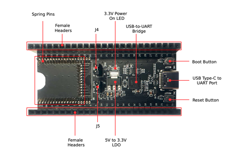
ESP-Module-Prog-1 - Front
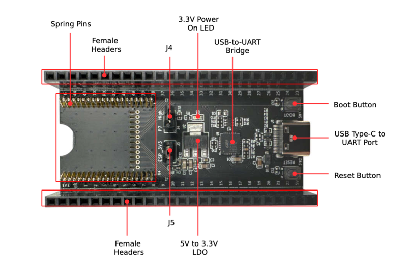
ESP-Module-Prog-1R - Front
The key components of the board are described in a clockwise direction.
Key Component |
Description |
|---|---|
Spring Pins |
Pins that fit into the module’s castellated holes for attaching and securing the module. |
Female Headers |
2.54 mm female headers that are connected to the pins of the module mounted in this board. For detailed information, please refer to Section Pin Descriptions. |
J4 |
Configures the strapping pin. For details, please refer to Section Strapping Pin Configuration. |
3.3 V Power On LED |
Lights up when the board is powered on with USB or power supply. |
USB-to-UART Bridge |
Single-chip USB to UART bridge that provides transfer rates of up to 3 Mbps. |
Boot Button |
Download button. Holding down Boot and then pressing EN initiates Firmware Download mode for downloading firmware through the serial port. |
USB Type-C to UART Interface |
Serves either as a power supply interface for the development board or as a communication interface to the chip via an on-board USB to UART bridge. |
Reset Button |
Reset button. |
5V-to-3.3V LDO |
Low Dropout Regulator (LDO). |
J5 |
Measures the current. For details, please refer to Section Measuring Current. |
Start Application Development
Before powering up your ESP-Module-Prog-1(R), please make sure that it is in good condition with no obvious signs of damage.
Required Hardware
Any one of the above-mentioned Espressif modules
USB-A to USB-C cable
PC (Windows, Linux, or macOS)
Note
Please make sure to use the appropriate USB cable. Some cables can only be used for charging, not for data transfer or program flashing.
Hardware Setup
Mount the module to ESP-Module-Prog-1(R) as follows:
Place the module lightly on ESP-Module-Prog-1(R), making sure the castellated holes on the module are aligned with the spring pins on the board.
Press the module inward until you hear a “click”, which indicates that the module has been successfully mounted.
Check if all the spring pins are clicked into the castellated holes. If there is a misalignment, you can use tweezers to poke the spring pins into the castellated holes.
Now the board is ready for software setup.
Software Setup
Recommended Approach
It is recommended to use the ESP-IDF development framework to flash the binary file (*.bin) to ESP-Module-Prog-1(R). Please refer to ESP-IDF Get Started to get a quick overview of setting up your development environment and flashing applications.
Alternative Approach
For Windows systems, you can also use the Flash Download Tool to flash the binary files.
Note
To flash binary files, the chip should be set to Firmware Download mode. This can be done either by the flash tool automatically, or by holding down the Boot button and tapping the Reset button.
After flashing binary files, the Flash Download Tool restarts your module and boots the flashed application by default.
Hardware Reference
This section provides more detailed information about the board’s hardware.
Block Diagram
The block diagram below shows the components of ESP-Module-Prog-1(R) and their interconnections.
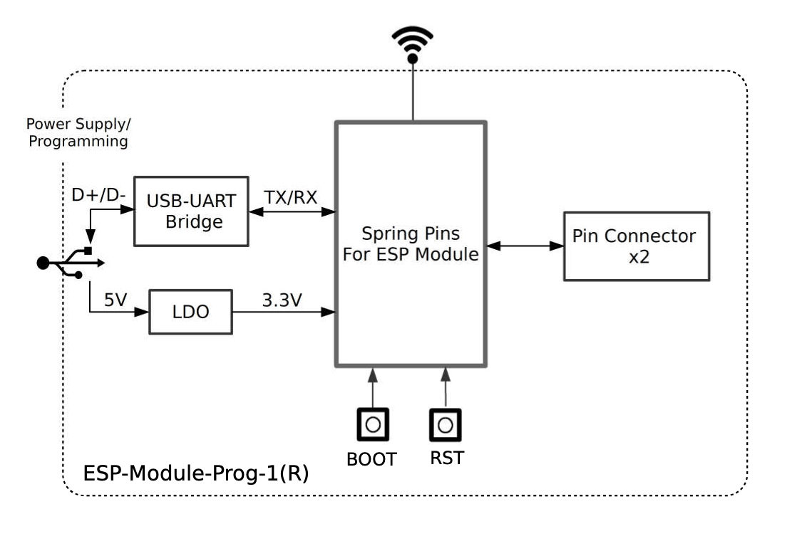
ESP-Module-Prog-1(R)
Power Source Select
There are three mutually exclusive ways to provide power to the board:
USB Type-C to UART port (default and recommended)
5V and GND header pins
3V3 and GND header pins
Strapping Pin Configuration
J4 on ESP-Module-Prog-1(R) is a 2-Pin header, with one end being P7 and one end being High (i.e. pull-up):
For some modules, the corresponding pin of P7 is not a strapping pin and no pull-up is needed for downloading. In this case, a jump cap is not required for J4.
For some modules, the corresponding pin of P7 is a strapping pin and a pull-up is needed for downloading. In this case, a jump cap is required for J4.
Note
For the corresponding pin of P7 on Espressif modules, please refer to ESP-Module-Prog-1(R) GPIO Map.
Measuring Current
J5 on ESP-Module-Prog-1(R) can be used to measure the current of the module.
Remove the J5 jumper cap: At this time, the peripherals and modules on the board are disconnected from the power supply, and the module current can be measured after the J5 pin is connected to the ammeter.
Install the J5 jump cap (factory default): the board functions normally.
Note
When using the 3V3 and GND header pins to power up the board, you need to remove the J5 jumper cap and connect an ammeter in series with the external circuit to measure the current of the module.
Pin Descriptions
The two tables below provide the Name and Signal of female headers on both sides of the board (J2 and J3). The pin names are shown in Figure ESP-Module-Prog-1 - Front. The numbering is the same as in the ESP-Module-Prog-1(R) Schematics (PDF). For the corresponding pin of each signal on Espressif modules, please refer to ESP-Module-Prog-1(R) GPIO Map.
J2
No. |
Name |
Signal |
|---|---|---|
1 |
3V3 |
3.3 V power supply |
2 |
EN |
CHIP_EN (High: enables the chip; Low: disables the chip. Pulled up by default.) |
3 |
1 |
P1 |
4 |
2 |
P2 |
5 |
3 |
P3 |
6 |
4 |
P4 |
7 |
5 |
P5 |
8 |
6 |
P6 |
9 |
7 |
P7 |
10 |
8 |
P8 |
11 |
9 |
P9 |
12 |
10 |
P10 |
13 |
11 |
P11 |
14 |
12 |
P12 |
15 |
13 |
P13 |
16 |
14 |
P14 |
17 |
15 |
P15 |
18 |
16 |
P16 |
19 |
17 |
P17 |
20 |
18 |
P18 |
21 |
19 |
P19 |
22 |
20 |
P20 |
23 |
21 |
P21 |
24 |
22 |
P22 |
25 |
5V |
5 V power supply |
J3
No. |
Name |
Signal |
|---|---|---|
1 |
G |
Ground |
2 |
44 |
P44 |
3 |
43 |
P43 |
4 |
TX |
TXD0 |
5 |
RX |
RXD0 |
6 |
42 |
P42 |
7 |
41 |
P41 |
8 |
40 |
P40 |
9 |
39 |
P39 |
10 |
38 |
P38 |
11 |
37 |
P37 |
12 |
36 |
P36 |
13 |
35 |
P35 |
14 |
34 |
P34 |
15 |
33 |
P33 |
16 |
32 |
P32 |
17 |
31 |
P31 |
18 |
30 |
P30 |
19 |
29 |
P29 |
20 |
28 |
P28 |
21 |
27 |
P27 |
22 |
26 |
P26 |
23 |
25 |
P25 |
24 |
24 |
P24 |
25 |
23 |
P23 |
Sample Request
Retail Orders
If you order a few samples, each ESP-Module-Prog-1(R) comes in an individual package in either antistatic bag or any packaging depending on your retailer.
For retail orders, please go to https://www.espressif.com/en/company/contact/buy-a-sample.
Wholesale Orders
If you order in bulk, the boards come in large cardboard boxes.
For wholesale orders, please go to https://www.espressif.com/en/contact-us/sales-questions.