The ESP-TEE framework on ESP32-C6 utilizes the inherent features of the RISC-V architecture, along with Espressif's proprietary hardware peripherals (given below), to ensure system isolation and enable a secure execution environment.
Inherent RISC-V CPU features
Machine (M) and User (U) privilege levels
PMP (Physical Memory Protection)
PMA (Physical Memory Attributes)
Espressif proprietary hardware
APM (Access Permission Management) peripheral
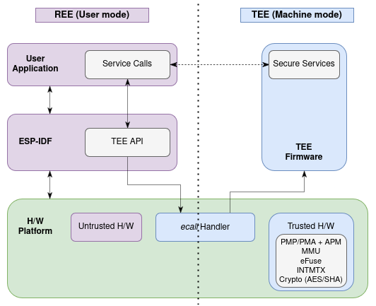
Together, these components enable the ESP32-C6 SoC to allocate the chip's hardware resources (internal memory, external memory, and peripherals) and software resources into two modes - Machine (M) mode and User (U) mode. The CPU can switch between these modes, with the TEE running in the higher privilege M-mode and the REE running in the lower privilege U-mode.
The Application Startup Flow is slightly modified when ESP-TEE is enabled. After a reset, the second stage bootloader loads both the TEE image and the application image from the boot device. Control is then handed over to the TEE, which configures memory, interrupts, and peripheral access settings before switching to the REE in U-mode to execute the application image.
In RISC-V architecture, each hardware thread (hart) operates at a specific privilege level, defined as a mode within one or more Control Status Registers (CSRs). These privilege levels serve as a protective measure, segregating different components within the software stack. Any attempts to execute operations or access assets that are not permitted by the current privilege mode will trigger an exception. The M-mode has the highest privileges and code running in M-mode is usually inherently trusted, as it has low-level access to the machine implementation.
For more information, please refer to the RISC-V Instruction Set Manual Volume II: Privileged Architecture, Version 1.10.
Physical Memory Protection (PMP) and Physical Memory Attributes (PMA) Checker
The ESP-TEE framework for ESP32-C6 leverages the RISC-V architecture's features, such as Physical Memory Protection (PMP) and Physical Memory Attributes (PMA) Checker, to manage access to system memory (internal SRAM and external Flash) within the TEE and REE contexts.
The PMP unit allows M-mode software to configure access privileges (read, write, execute) for required memory regions. This mechanism enforces resource isolation between the TEE and REE, adhering to the system's predefined policies and ensuring secure access control.
The PMAC unit enhances security by providing additional permission checks, including configurable memory types and customizable attributes for required memory regions.
For more details, see ESP32-C6 Technical Reference Manual > Physical Memory Protection [PDF] and Physical Memory Attribute (PMA) Checker [PDF].
The Access Permission Management (APM) module is a ESP32-C6-hardware peripheral designed to enforce isolation between the TEE and REE, both for the system memory and peripherals. It is composed of two primary components: the TEE controller and the APM controller, each with its dedicated registers. The TEE-related registers are used to configure the security mode of each master (e.g., HP CPU or DMA acting as a master accessing memory), and the APM-related registers are used to specify the access permission and access address range of each security mode.
APM enhances system isolation in areas where the PMP and PMA mechanisms fall short. The number of entries for PMP/PMA are limited, and these mechanisms cannot govern accesses by the low-power core or other masters, such as the GDMA.
For more details, see ESP32-C6 Technical Reference Manual > Permission Control (PMS) [PDF].
Note
For ESP32-C6, the Access Permission Management (APM) and the Physical Memory Protection (PMP) together play the role of Permission Control (PMS).
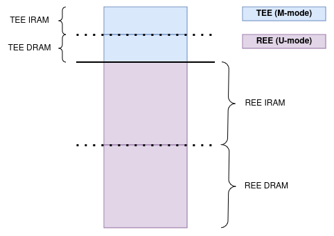
A region at the top of the HP SRAM is reserved for the TEE, allocated for TEE code execution and runtime data storage, including stack and heap. Permissions for all memory regions within the SRAM are managed by the PMP and configured by the TEE.
The REE memory is partitioned into IRAM (text: Read/Execute) and DRAM (data: Read/Write) sections, with the division controlled by the PMP.
However, the TEE memory is divided into IRAM and DRAM sections, with division enforced by the PMA.
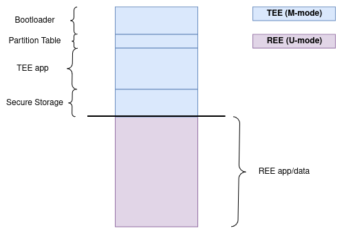
Designated partitions in the external flash are reserved for the TEE, serving various purposes, including TEE code execution via XIP, secure storage, and OTA data. The PMS safeguards these partitions from unauthorized access, with the APM module protecting the MMU and SPI1 controller registers, and the PMP securing the cache.
The key interfaces for flash memory protection are the cache connected to SPI0, which provides virtual access to flash memory, and the SPI1 controller, which provides physical access. By default, the cache and the MMU registers are secured by the PMS, preventing virtual access to the TEE-related flash partitions from the REE.
When Flash Encryption is enabled, the REE can still access TEE flash regions via SPI1, but read operations will return encrypted data. Since neither the REE nor TEE has direct access to the flash encryption key, this prevents attackers from inferring TEE contents through direct reads.
Additionally with Secure Boot enabled, any unauthorized modifications to the TEE firmware will be detected during boot, causing signature verification to fail. Thus, the combination of Flash Encryption and Secure Boot provides a robust level of protection suitable for most applications.
However, do note that while the TEE firmware integrity is protected, other TEE partitions (e.g., Secure Storage, TEE OTA data) can be modified through direct writes.
For stronger isolation, you can enable CONFIG_SECURE_TEE_EXT_FLASH_MEMPROT_SPI1, which completely blocks access to all TEE flash regions via SPI1 for the REE. With this setting, all SPI flash read, write, and erase operations are routed through service calls to the TEE. While this option provides enhanced security, it introduces some performance overhead.
The following peripherals are protected using the APM module and accessible only by the TEE. Any direct access to these peripherals from the REE will trigger an exception. These peripherals are chosen for protection because access from the REE could compromise system security or interfere with secure services like secure storage and attestation.
The TEE firmware is primarily loaded and executed from the internal secure SRAM. However, due to SRAM's limited capacity, some portions of the TEE firmware are stored and executed from a dedicated external flash partition, which is protected from access by the REE. This firmware is responsible for securely configuring the system, ensuring isolation and protection of both internal and external memory, as well as peripherals.
The TEE and REE each have their own vector tables, with one interrupt pin dedicated to secure interrupts. TEE interrupts are always given higher priority over REE interrupts. The TEE firmware provides APIs for registering secure, peripheral-specific interrupt handlers.
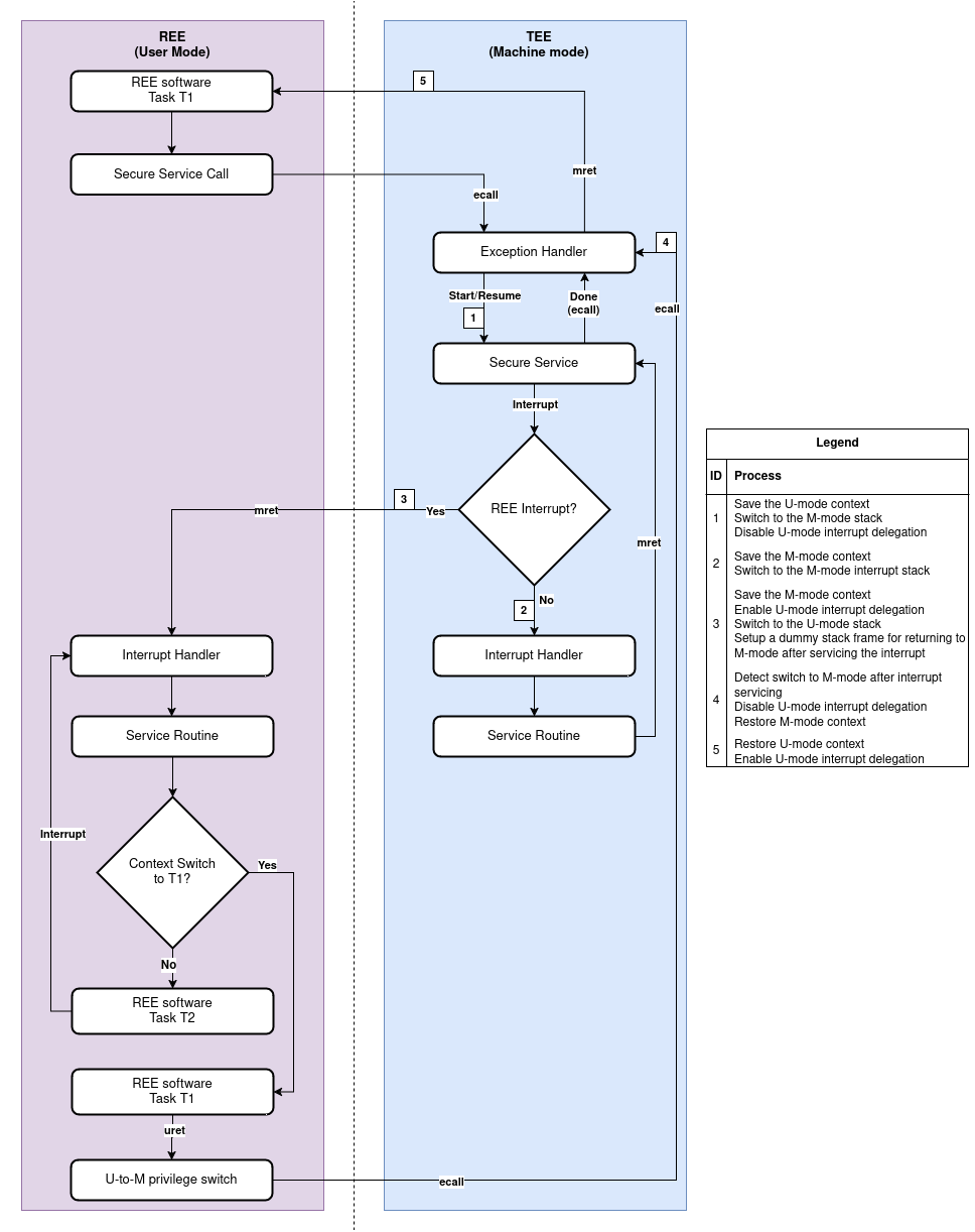
Depending on the interrupt state, an interrupt may either be handled within the current execution environment's vector table or trigger a privilege switch, transferring the handling to the other environment's vector table. There are four possible scenarios for interrupt handling, as outlined in the table below.
Once the interrupt is handled in the other execution environment, execution returns to the environment where the interrupt was initially triggered.
Scenario
Description
TEE interrupts while operating in TEE
Trapped in the TEE at the M-mode exception handler
REE interrupts while operating in REE
Trapped in the REE at the U-mode exception handler
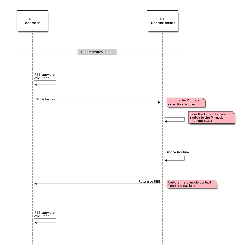
TEE interrupts while operating in REE
Trapped in the TEE at the M-mode exception handler and
return to the REE after processing
REE interrupts while operating in TEE
Trapped in the TEE at the M-mode exception handler,
jump to the U-mode exception handler in the REE and
return to the TEE after processing
ESP-TEE: Handling TEE interrupts occurring in REE
ESP-TEE: Handling REE interrupts occurring in TEE
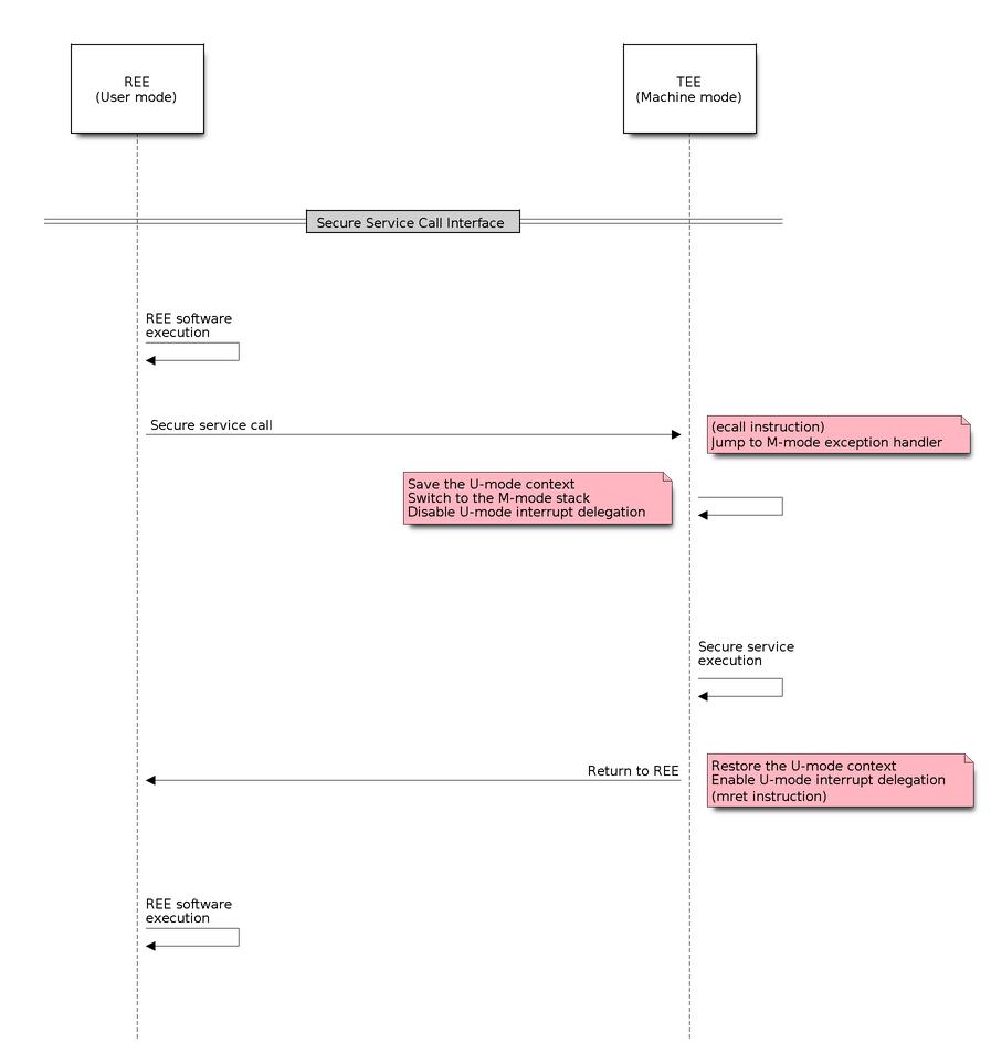
The secure service call interface allows the REE application to request trusted (TEE) operations, triggering the secure service dispatcher function. The dispatcher parses the input parameters, identifies the correct service to invoke, and forwards the request to the appropriate service handler.
Serving as the entry point to the TEE, the dispatcher manages the secure service call. Upon receiving a request, it processes the input arguments and executes the requested service.
After the secure service completes, the dispatcher handles the return process and initiates a privilege switch, restoring control to the REE at the point of the original call. Note that the privilege levels are switched as a part of the pre and post processing routines of the secure service dispatcher.
This is essential during operations like flash access through the SPI1 bus, where the flash cache may be disabled, to prevent concurrent access to flash from multiple entities.
Ensure that the custom service call numbers does not conflict with the default service call table. The ESP-TEE framework parses the custom service call table along with the default table to generate relevant header files used in applications.
Define the function corresponding to the custom service call in the TEE. This function will execute whenever the REE invokes the service with the associated number.
Example Implementation
int_ss_custom_sec_srv_op(void*arg){// Perform the intended taskreturn0;}
The function name should have the prefix _ss_ before the name and must match the name specified in the .yml file.
For reference, all default service call functions are defined in the file.
Define the CMakeLists.txt for the custom component
idf_build_get_property(esp_tee_buildESP_TEE_BUILD)if(esp_tee_build)## Headers, sources and dependent components for the TEE-buildelse()## Headers, sources and dependent components for the REE-buildendif()idf_component_register(...)
Project-level
Modify the top-level CMakeLists.txt of your project to include the custom_sec_srv.cmake file before calling the project() command.
The ESP-TEE framework utilizes the pytest in ESP-IDF framework for executing the dedicated unit tests on the target. The test application includes cases spanning the modules listed below and can be located in the components directory at esp_tee/test_apps.
Secure service call interface
Interrupts and exception handling
Privilege violation
Cryptographic operations
TEE OTA updates
Secure storage
Attestation
Please follow the steps given here for running the tests locally. For example, if you want to execute the TEE test suite for ESP32-C6 with all the available sdkconfig files (assuming you have ESP-IDF setup), run the following steps.