Establish Serial Connection with ESP32
Establishing a serial connection with the ESP32 target device could be done using a USB-to-UART bridge.
Some development boards have the USB-to-UART bridge installed. If a board does not have a bridge then an external bridge may be used.
USB-to-UART Bridge on Development Board
For boards with an installed USB-to-UART bridge, the connection between the personal computer and the bridge is USB and between the bridge and ESP32 is UART.
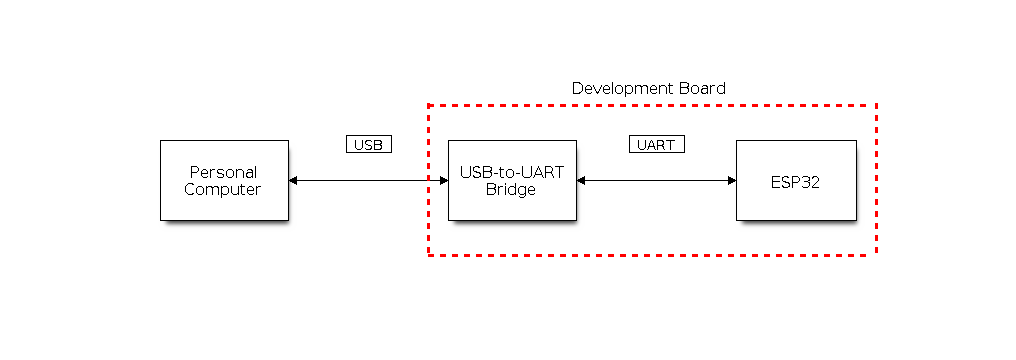
Development Board with USB-to-UART Bridge
External USB-to-UART Bridge
Sometimes the USB-to-UART bridge is external. This is often used in small development boards or finished products when space and costs are crucial.
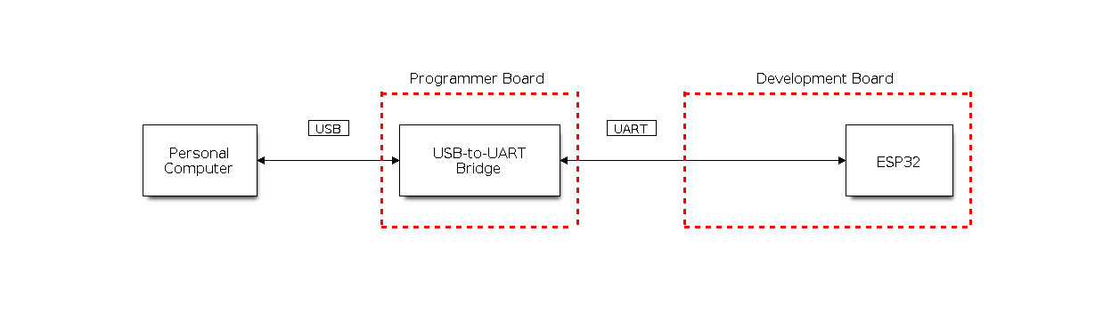
External USB-to-UART Bridge
Flash Using UART
This section provides guidance on how to establish a serial connection between ESP32 and PC using USB-to-UART Bridge, either installed on the development board or external.
Connect ESP32 to PC
Connect the ESP32 board to the PC using the USB cable. If device driver does not install automatically, identify USB-to-UART bridge on your ESP32 board (or external converter dongle), search for drivers in internet and install them.
Below is the list of USB to serial converter chips installed on most of the ESP32 boards produced by Espressif together with links to the drivers:
Please check the board user guide for specific USB-to-UART bridge chip used. The drivers above are primarily for reference. Under normal circumstances, the drivers should be bundled with an operating system and automatically installed upon connecting the board to the PC.
For devices downloaded using a USB-to-UART bridge, you can run the following command including the optional argument to define the baud rate.
idf.py -p PORT [-b BAUD] flash
Replace PORT with the device name for the serial port of your ESP32 board. Please note that -b is an optional argument. If you do not specify the baud rate, the default baud rate is 460800. If you need to specify the baud rate, replace BAUD with the baud rate you need.
To check the port name on Windows, please refer to check-port-on-windows. For Linux and macOS users, please see check-port-on-linux-and-macos.
For example, if the port name is COM3 on Windows and your desired baud rate is 115200, you can run the following command to flash the device:
idf.py -p COM3 -b 115200 flash
For Linux users, if the port name is /dev/ttyUSB0 and the desired baud rate is 115200, you can run the following command to flash the device:
idf.py -p /dev/ttyUSB0 -b 115200 flash
For macOS users, if the port name is /dev/cu.usbserial-1401 and the desired baud rate is 115200, you can run the following command to flash the device:
idf.py -p /dev/cu.usbserial-1401 -b 115200 flash
Note
If the device does not support the auto download mode, you need to get into the download mode manually. To do so, press and hold the BOOT button and then press the RESET button once. After that release the BOOT button.
Check Port on Windows
Check the list of identified COM ports in the Windows Device Manager. Disconnect ESP32 and connect it back, to verify which port disappears from the list and then shows back again.
Figures below show serial port for ESP32 DevKitC and ESP32 WROVER KIT
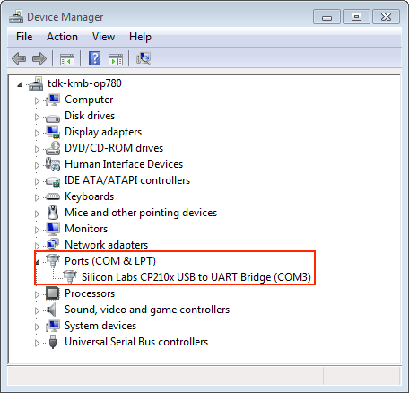
USB to UART bridge of ESP32-DevKitC in Windows Device Manager
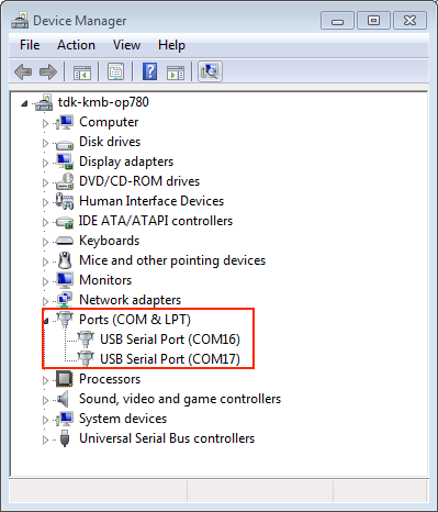
Two USB Serial Ports of ESP-WROVER-KIT in Windows Device Manager
Check Port on Linux and macOS
To check the device name for the serial port of your ESP32 board (or external converter dongle), run this command two times, first with the board/dongle unplugged, then with plugged in. The port which appears the second time is the one you need:
Linux
ls /dev/tty*
macOS
ls /dev/cu.*
Note
macOS users: if you do not see the serial port then check you have the USB/serial drivers installed. See Section Connect ESP32 to PC for links to drivers. For macOS High Sierra (10.13), you may also have to explicitly allow the drivers to load. Open System Preferences -> Security & Privacy -> General and check if there is a message shown here about "System Software from developer ..." where the developer name is Silicon Labs or FTDI.
Adding User to dialout or uucp on Linux
The currently logged user should have read and write access the serial port over USB. On most Linux distributions, this is done by adding the user to dialout group with the following command:
sudo usermod -a -G dialout $USER
on Arch Linux this is done by adding the user to uucp group with the following command:
sudo usermod -a -G uucp $USER
Note
Make sure you re-login to enable read and write permissions for the serial port.
Verify Serial Connection
Now verify that the serial connection is operational. You can do this using a serial terminal program by checking if you get any output on the terminal after resetting ESP32.
The default console baud rate on ESP32 is 115200.
Windows and Linux
In this example, we use the PuTTY SSH Client, available for both Windows and Linux. You can use other serial programs and set communication parameters as shown below.
Run terminal and set identified serial port. Baud rate = 115200 (if needed, change this to the default baud rate of the chip in use), data bits = 8, stop bits = 1, and parity = N. Below are example screenshots of setting the port and such transmission parameters (in short described as 115200-8-1-N) on Windows and Linux. Remember to select exactly the same serial port you have identified in steps above.
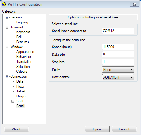
Setting Serial Communication in PuTTY on Windows
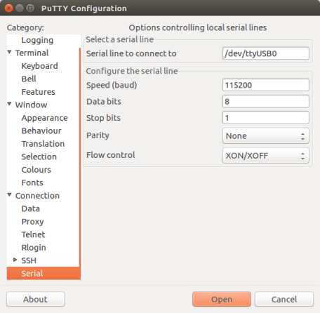
Setting Serial Communication in PuTTY on Linux
Then open serial port in terminal and check, if you see any log printed out by ESP32. The log contents depend on application loaded to ESP32, see Example Output. If no log has been printed out, see Troubleshooting.
Note
Close the serial terminal after verification that communication is working. If you keep the terminal session open, the serial port will be inaccessible for uploading firmware later.
macOS
To spare you the trouble of installing a serial terminal program, macOS offers the screen command.
As discussed in Check port on Linux and macOS, run:
ls /dev/cu.*
You should see similar output:
/dev/cu.Bluetooth-Incoming-Port /dev/cu.SLAB_USBtoUART /dev/cu.SLAB_USBtoUART7
The output varies depending on the type and the number of boards connected to your PC. Then pick the device name of your board and run (if needed, change "115200" to the default baud rate of the chip in use):
screen /dev/cu.device_name 115200
Replace
device_namewith the name found runningls /dev/cu.*.What you are looking for is some log displayed by the screen. The log contents depend on application loaded to ESP32, see Example Output. If no log has been printed out, see Troubleshooting. To exit the current screen session, type
Ctrl-A + K.
Note
Do not forget to exit the current screen session after verifying that the communication is working. If you fail to do it and just close the terminal window, the serial port will be inaccessible for uploading firmware later.
Troubleshooting
If there is no log output, check
if the required power is supplied to ESP32
if the board was reset after starting the terminal program
if the selected serial port is the correct one by using the method stated in Check Port on Windows and Check Port on Linux and macOS
if the serial port is not being used by another program
if settings of the serial port in serial terminal programs are applicable to corresponding applications
if your application is expected to output some log. In details, if
Component config>Log>Log Level>Default log verbosity (Info)is set toNo output, no log will be printed out. You can change this setting inmenuconfig.if the log output has not been disabled (use hello world application to test)
Example Output
An example log is shown below. Reset the board if you do not see anything.
ets Jun  8 2016 00:22:57

rst:0x5 (DEEPSLEEP_RESET),boot:0x13 (SPI_FAST_FLASH_BOOT)
ets Jun  8 2016 00:22:57

rst:0x7 (TG0WDT_SYS_RESET),boot:0x13 (SPI_FAST_FLASH_BOOT)
configsip: 0, SPIWP:0x00
clk_drv:0x00,q_drv:0x00,d_drv:0x00,cs0_drv:0x00,hd_drv:0x00,wp_drv:0x00
mode:DIO, clock div:2
load:0x3fff0008,len:8
load:0x3fff0010,len:3464
load:0x40078000,len:7828
load:0x40080000,len:252
entry 0x40080034
I (44) boot: ESP-IDF v2.0-rc1-401-gf9fba35 2nd stage bootloader
I (45) boot: compile time 18:48:10
...
If you can see readable log output, it means serial connection is working and you are ready to proceed with installation and finally upload an application to ESP32.
Note
For some serial port wiring configurations, the serial RTS & DTR pins need to be disabled in the terminal program before the ESP32 booting and producing serial output. This depends on the hardware itself, most development boards (including all Espressif boards) do not have this issue. The issue is present if RTS & DTR are wired directly to the EN & GPIO0 pins. See the esptool documentation for more details.
If you got here from Connect Your Device for Windows, Linux, or macOS when installing s/w for ESP32 development, then you can continue with Configure Your Project for Windows, Linux, or macOS.