Previous Versions of ESP32 Modules and Boards
This sections contains overview and links to documentation of previous version ESP32 Modules and Boards that have been replaced with newer versions or discontinued. It is maintained for convenience of users as several of these boards are still in use and some may still be available for purchase.
To see the latest development boards, please refer to section ESP32 Modules and Boards.
ESP32-PICO-KIT V4
The smallest ESP32 development board with all the components required to connect it directly to a PC USB port, and pin headers to plug into a mini breadboard. It is equipped with ESP32-PICO-D4 module that integrates 4 MB flash memory, a crystal oscillator, filter capacitors and RF matching circuit in one single package. As result, the fully functional development board requires only a few external components that can easy fit on a 20 x 52 mm PCB including antenna, LDO, USB-UART bridge and two buttons to reset it and put into download mode.
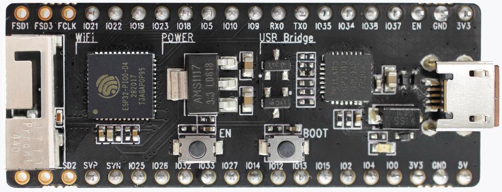
ESP32-PICO-KIT V4 board
Comparing to ESP32-PICO-KIT V3, this version has revised printout and reduced number of exposed pins. Instead of 20, only 17 header pins are populated, so V4 can fit into a mini breadboard.
Documentation
ESP32-PICO-KIT V3
The first public release of Espressif’s ESP32-PICO-D4 module on a mini development board. The board has a USB port for programming and debugging and two rows of 20 pin headers to plug into a breadboard. The ESP32-PICO-D4 module itself is small and requires only a few external components. Besides two core CPUs it integrates 4MB flash memory, a crystal oscillator and antenna matching components in one single 7 x 7 mm package. As a result the module and all the components making the complete development board fit into 20 x 52 mm PCB.

ESP32-PICO-KIT V3 board
Documentation
ESP32 Core Board V2 / ESP32 DevKitC
Small and convenient development board with ESP-WROOM-32 module installed, break out pin headers and minimum additional components. Includes USB to serial programming interface, that also provides power supply for the board. Has pushbuttons to reset the board and put it in upload mode.
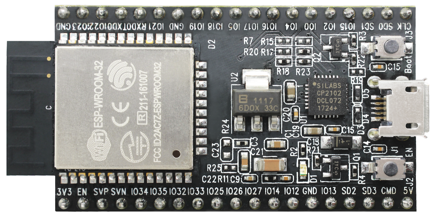
ESP32 Core Board V2 / ESP32 DevKitC board
ESP-WROVER-KIT V3
The ESP-WROVER-KIT V3 development board has dual port USB to serial converter for programming and JTAG interface for debugging. Power supply is provided by USB interface or from standard 5 mm power supply jack. Power supply selection is done with a jumper and may be put on/off with a separate switch. This board has MicroSD card slot, 3.2” SPI LCD screen and dedicated header to connect a camera. It provides RGB diode for diagnostics. Includes 32.768 kHz XTAL for internal RTC to operate it in low power modes.
As all previous versions of ESP-WROVER-KIT boards, it is ready to accommodate an ESP32-WROOM-32 or ESP32-WROVER module.
This is the first release of ESP-WROVER-KIT shipped with ESP32-WROVER module installed by default. This release also introduced several design changes to conditioning and interlocking of signals to the bootstrapping pins. Also, a zero Ohm resistor (R166) has been added between WROVER/WROOM module and VDD33 net, which can be desoldered, or replaced with a shunt resistor, for current measurement. This is intended to facilitate power consumption analysis in various operation modes of ESP32. Refer to schematic - the changes are enclosed in green border.
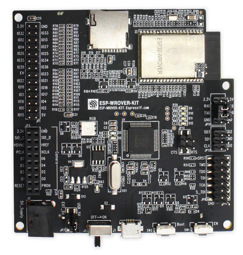
ESP-WROVER-KIT V3 board
The camera header has been changed from male back to female. The board soldermask is matte black. The board on picture above has ESP32-WROVER is installed.
ESP-WROVER-KIT V2
This is updated version of ESP32 DevKitJ V1 described above with design improvements identified when DevKitJ was in use, e.g. improved support for SD card. By default board has ESP-WROOM-32 module installed.

ESP-WROVER-KIT V2 board
Comparing to previous version, this board has a shiny black finish and a male camera header.
ESP-WROVER-KIT V1 / ESP32 DevKitJ V1
The first version of ESP-WROVER-KIT development board. Shipped with ESP-WROOM-32 on board.
ESP-WROVER-KIT has dual port USB to serial converter for programming and JTAG interface for debugging. Power supply is provided by USB interface or from standard 5 mm power supply jack. Power supply selection is done with a jumper and may be put on/off with a separate switch. The board has MicroSD card slot, 3.2” SPI LCD screen and dedicated header to connect a camera. It provides RGB diode for diagnostics. Includes 32.768 kHz XTAL for internal RTC to operate it in low power modes.
All versions of ESP-WROVER-KIT are ready to accommodate an ESP-WROOM-32 or ESP32-WROVER module.
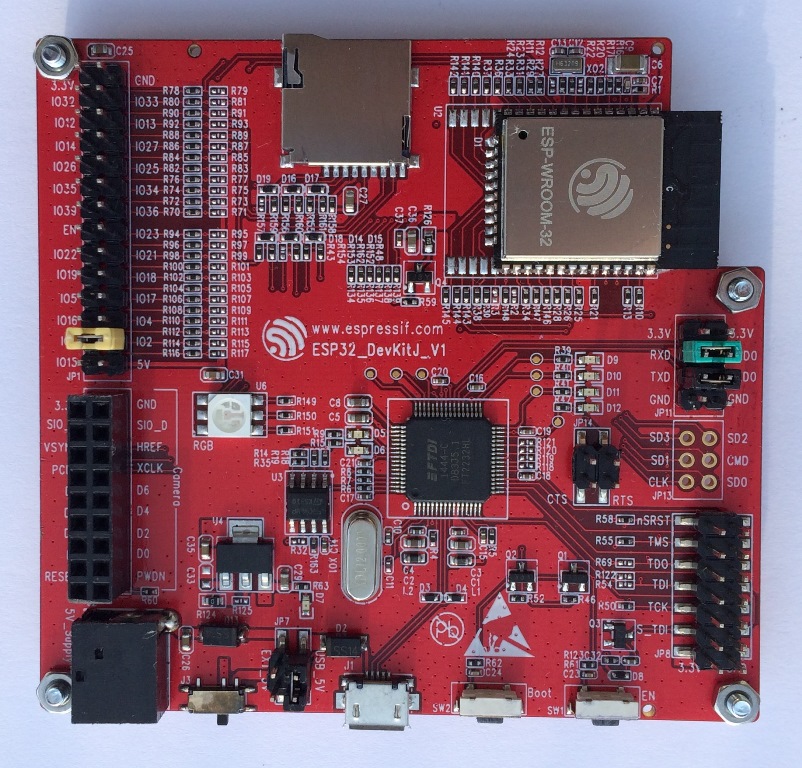
ESP-WROVER-KIT V1 / ESP32 DevKitJ V1 board
The board has red soldermask.
Documentation
ESP32 Demo Board V2
One of first feature rich evaluation boards that contains several pin headers, dip switches, USB to serial programming interface, reset and boot mode press buttons, power switch, 10 touch pads and separate header to connect LCD screen.
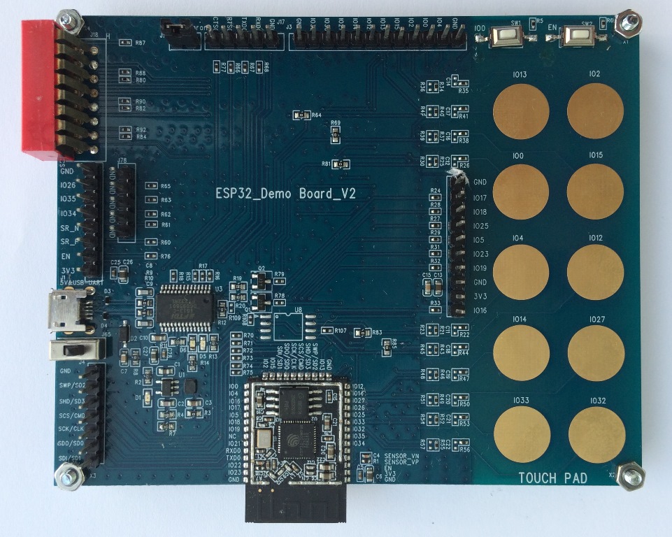
ESP32 Demo Board V2
Production of this board is discontinued.