I2C
An I2C (Inter-Integrated Circuit) bus can be used for communication with several external devices connected to the same bus as ESP32. There are two I2C controllers on board of the ESP32, each of which can be set to master mode or slave mode.
Overview
The following sections will walk you through typical steps to configure and operate the I2C driver:
- Configure Driver - select driver’s parameters like master or slave mode, set specific GPIO pins to act as SDA and SCL, set the clock speed, etc.
- Install Driver- activate driver in master or slave mode to operate on one of the two I2C controllers available on ESP32.
- Run Communication:
- Master Mode - run communication acting as a master
- Slave Mode - get slave responding to messages from the master
- Interrupt Handling - configure and service I2C interrupts.
- Going Beyond Defaults - adjust timing, pin configuration and other parameters of the I2C communication.
- Error Handling - how to recognize and handle driver configuration and communication errors.
- Delete Driver- on communication end to free resources used by the I2C driver.
The top level identification of an I2C driver is one of the two port numbers selected from i2c_port_t. The mode of operation for a given port is provided during driver configuration by selecting either “master” or “slave” from i2c_mode_t.
Configure Driver
The first step to establishing I2C communication is to configure the driver. This is done by setting several parameters contained in i2c_config_t structure:
I2C operation mode - select either slave or master from
i2c_opmode_tSettings of the communication pins:
- GPIO pin numbers assigned to the SDA and SCL signals
- Whether to enable ESP32’s internal pull up for respective pins
I2C clock speed, if this configuration concerns the master mode
If this configuration concerns the slave mode:
- Whether 10 bit address mode should be enabled
- The slave address
Then, to initialize configuration for a given I2C port, call function i2c_param_config() with the port number and i2c_config_t structure as the function call parameters.
At this stage i2c_param_config() also sets “behind the scenes” couple of other I2C configuration parameters to commonly used default values. To check what are the values and how to change them, see Going Beyond Defaults.
Install Driver
Having the configuration initialized, the next step is to install the I2C driver by calling i2c_driver_install(). This function call requires the following parameters:
- The port number, one of the two ports available, selected from
i2c_port_t - The operation mode, slave or master selected from
i2c_opmode_t - Sizes of buffers that will be allocated for sending and receiving data in the slave mode
- Flags used to allocate the interrupt
Run Communication
With the I2C driver installed, ESP32 is ready to communicate with other I2C devices. Programming of communication depends on whether selected I2C port operates in a master or a slave mode.
Master Mode
ESP32’s I2C port working in the master made is responsible for establishing communication with slave I2C devices and sending commands to trigger actions by slaves, like doing a measurement and sending back a result.
To organize this process the driver provides a container, called a “command link”, that should be populated with a sequence of commands and then passed to the I2C controller for execution.
Master Write
An example of building a commend link for I2C master sending n bytes to slave is shown below:
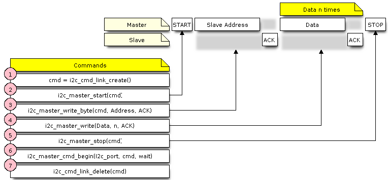
I2C command link - master write example
The following describes how the command link for a “master write” is set up and what comes inside:
The first step is to create a command link with
i2c_cmd_link_create().Then the command link is populated with series of data to be sent to the slave:
- Start bit -
i2c_master_start() - Single byte slave address -
i2c_master_write_byte(). The address is provided as an argument of this function call. - One or more bytes of data as an argument of
i2c_master_write(). - Stop bit -
i2c_master_stop()
Both
i2c_master_write_byte()andi2c_master_write()commands have additional argument defining whether slave should acknowledge received data or not.- Start bit -
- Execution of command link by I2C controller is triggered by calling
i2c_master_cmd_begin(). - As the last step, after sending of the commands is finished, the resources used by the command link are released by calling
i2c_cmd_link_delete().
Master Read
There is a similar sequence of steps for the master to read the data from a slave.
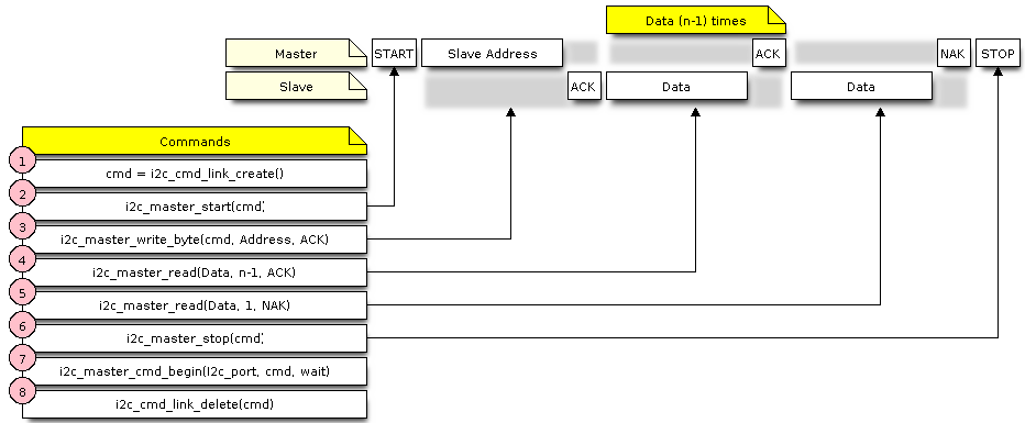
I2C command link - master read example
When reading the data, instead of “i2c_master_read…”, the command link is populated with i2c_master_read_byte() and / or i2c_master_read(). Also, the last read is configured for not providing an acknowledge by the master.
Master Write or Read?
After sending a slave’s address, see step 3 on pictures above, the master either writes to or reads from the slave. The information what the master will actually do is hidden in the least significant bit of the slave’s address.
Therefore the command link instructing the slave that the master will write the data contains the address like (ESP_SLAVE_ADDR << 1) | I2C_MASTER_WRITE and looks as follows:
i2c_master_write_byte(cmd, (ESP_SLAVE_ADDR << 1) | I2C_MASTER_WRITE, ACK_CHECK_EN)
By similar token the command link to read from the slave looks as follows:
i2c_master_write_byte(cmd, (ESP_SLAVE_ADDR << 1) | I2C_MASTER_READ, ACK_CHECK_EN)
Slave Mode
The API provides functions to read and write data by the slave - * i2c_slave_read_buffer() and i2c_slave_write_buffer(). An example of using these functions is provided in peripherals/i2c.
Interrupt Handling
To register an interrupt handler, call function i2c_isr_register(), to delete the handler call i2c_isr_free(). Description of interrupts triggered by I2C controller is provided in the ESP32 Technical Reference Manual (PDF).
Going Beyond Defaults
There are couple of I2C communication parameters setup during driver configuration (when calling i2c_param_config(), see Configure Driver), to some default commonly used values. Some parameters are also already configured in registers of the I2C controller. These parameters can be changed to user defined values by calling dedicated functions:
Period of SCL pulses being high and low -
i2c_set_period()SCL and SDA signal timing used during generation of start / stop signals -
i2c_set_start_timing()/i2c_set_stop_timing()Timing relationship between SCL and SDA signals when sampling by slave, as well as when transmitting by master -
i2c_set_data_timing()I2C timeout -
i2c_set_timeout()Note
The timing values are defined in APB clock cycles. The frequency of APB is specified in
I2C_APB_CLK_FREQ.What bit, LSB or MSB, is transmitted / received first -
i2c_set_data_mode()selectable out of modes defined ini2c_trans_mode_t
Each one of the above functions has a _get_ counterpart to check the currently set value.
To see the default values of parameters setup during driver configuration, please refer to file driver/i2c.c looking up defines with _DEFAULT suffix.
With function i2c_set_pin() it is also possible to select different SDA and SCL pins and alter configuration of pull ups, changing what has been already entered with i2c_param_config().
Note
ESP32’s internal pull ups are in the range of some tens of kOhm, and as such in most cases insufficient for use as I2C pull ups by themselves. We suggest to add external pull ups as well, with values as described in the I2C standard.
Error Handling
Most of driver’s function return the ESP_OK on successful completion or a specific error code on a failure. It is a good practice to always check the returned values and implement the error handling. The driver is also printing out log messages, when e.g. checking the correctness of entered configuration, that contain explanation of errors. For details please refer to file driver/i2c.c looking up defines with _ERR_STR suffix.
Use dedicated interrupts to capture communication failures. For instance there is I2C_TIME_OUT_INT interrupt triggered when I2C takes too long to receive data. See Interrupt Handling for related information.
To reset internal hardware buffers in case of communication failure, you can use i2c_reset_tx_fifo() and i2c_reset_rx_fifo().
Delete Driver
If the I2C communication is established with i2c_driver_install() for some specific period of time and then not required, the driver may be removed to free allocated resources by calling i2c_driver_delete().
Application Example
I2C master and slave example: peripherals/i2c.
API Reference
Header File
Functions
-
esp_err_t
i2c_driver_install(i2c_port_t i2c_num, i2c_mode_t mode, size_t slv_rx_buf_len, size_t slv_tx_buf_len, int intr_alloc_flags)¶ I2C driver install.
- Note
- Only slave mode will use this value, driver will ignore this value in master mode.
- Note
- Only slave mode will use this value, driver will ignore this value in master mode.
- Note
- In master mode, if the cache is likely to be disabled(such as write flash) and the slave is time-sensitive,
ESP_INTR_FLAG_IRAMis suggested to be used. In this case, please use the memory allocated from internal RAM in i2c read and write function, because we can not access the psram(if psram is enabled) in interrupt handle function when cache is disabled. - Return
- ESP_OK Success
- ESP_ERR_INVALID_ARG Parameter error
- ESP_FAIL Driver install error
- Parameters
i2c_num: I2C port numbermode: I2C mode( master or slave )slv_rx_buf_len: receiving buffer size for slave mode
- Parameters
slv_tx_buf_len: sending buffer size for slave mode
- Parameters
intr_alloc_flags: Flags used to allocate the interrupt. One or multiple (ORred) ESP_INTR_FLAG_* values. See esp_intr_alloc.h for more info.
-
esp_err_t
i2c_driver_delete(i2c_port_t i2c_num)¶ I2C driver delete.
- Return
- ESP_OK Success
- ESP_ERR_INVALID_ARG Parameter error
- Parameters
i2c_num: I2C port number
-
esp_err_t
i2c_param_config(i2c_port_t i2c_num, const i2c_config_t *i2c_conf)¶ I2C parameter initialization.
- Return
- ESP_OK Success
- ESP_ERR_INVALID_ARG Parameter error
- Parameters
i2c_num: I2C port numberi2c_conf: pointer to I2C parameter settings
-
esp_err_t
i2c_reset_tx_fifo(i2c_port_t i2c_num)¶ reset I2C tx hardware fifo
- Return
- ESP_OK Success
- ESP_ERR_INVALID_ARG Parameter error
- Parameters
i2c_num: I2C port number
-
esp_err_t
i2c_reset_rx_fifo(i2c_port_t i2c_num)¶ reset I2C rx fifo
- Return
- ESP_OK Success
- ESP_ERR_INVALID_ARG Parameter error
- Parameters
i2c_num: I2C port number
-
esp_err_t
i2c_isr_register(i2c_port_t i2c_num, void (*fn)(void *), void *arg, int intr_alloc_flags, intr_handle_t *handle, )¶ I2C isr handler register.
- Return
- ESP_OK Success
- ESP_ERR_INVALID_ARG Parameter error
- Parameters
i2c_num: I2C port numberfn: isr handler functionarg: parameter for isr handler functionintr_alloc_flags: Flags used to allocate the interrupt. One or multiple (ORred) ESP_INTR_FLAG_* values. See esp_intr_alloc.h for more info.handle: handle return from esp_intr_alloc.
-
esp_err_t
i2c_isr_free(intr_handle_t handle)¶ to delete and free I2C isr.
- Return
- ESP_OK Success
- ESP_ERR_INVALID_ARG Parameter error
- Parameters
handle: handle of isr.
-
esp_err_t
i2c_set_pin(i2c_port_t i2c_num, int sda_io_num, int scl_io_num, gpio_pullup_t sda_pullup_en, gpio_pullup_t scl_pullup_en, i2c_mode_t mode)¶ Configure GPIO signal for I2C sck and sda.
- Return
- ESP_OK Success
- ESP_ERR_INVALID_ARG Parameter error
- Parameters
i2c_num: I2C port numbersda_io_num: GPIO number for I2C sda signalscl_io_num: GPIO number for I2C scl signalsda_pullup_en: Whether to enable the internal pullup for sda pinscl_pullup_en: Whether to enable the internal pullup for scl pinmode: I2C mode
-
i2c_cmd_handle_t
i2c_cmd_link_create()¶ Create and init I2C command link.
- Note
- Before we build I2C command link, we need to call i2c_cmd_link_create() to create a command link. After we finish sending the commands, we need to call i2c_cmd_link_delete() to release and return the resources.
- Return
- i2c command link handler
-
void
i2c_cmd_link_delete(i2c_cmd_handle_t cmd_handle)¶ Free I2C command link.
- Note
- Before we build I2C command link, we need to call i2c_cmd_link_create() to create a command link. After we finish sending the commands, we need to call i2c_cmd_link_delete() to release and return the resources.
- Parameters
cmd_handle: I2C command handle
-
esp_err_t
i2c_master_start(i2c_cmd_handle_t cmd_handle)¶ Queue command for I2C master to generate a start signal.
- Note
- Only call this function in I2C master mode Call i2c_master_cmd_begin() to send all queued commands
- Return
- ESP_OK Success
- ESP_ERR_INVALID_ARG Parameter error
- Parameters
cmd_handle: I2C cmd link
-
esp_err_t
i2c_master_write_byte(i2c_cmd_handle_t cmd_handle, uint8_t data, bool ack_en)¶ Queue command for I2C master to write one byte to I2C bus.
- Note
- Only call this function in I2C master mode Call i2c_master_cmd_begin() to send all queued commands
- Return
- ESP_OK Success
- ESP_ERR_INVALID_ARG Parameter error
- Parameters
cmd_handle: I2C cmd linkdata: I2C one byte command to write to busack_en: enable ack check for master
-
esp_err_t
i2c_master_write(i2c_cmd_handle_t cmd_handle, uint8_t *data, size_t data_len, bool ack_en)¶ Queue command for I2C master to write buffer to I2C bus.
- Note
- Only call this function in I2C master mode Call i2c_master_cmd_begin() to send all queued commands
- Note
- If the psram is enabled and intr_flag is
ESP_INTR_FLAG_IRAM, please use the memory allocated from internal RAM. - Return
- ESP_OK Success
- ESP_ERR_INVALID_ARG Parameter error
- Parameters
cmd_handle: I2C cmd linkdata: data to send
- Parameters
data_len: data lengthack_en: enable ack check for master
-
esp_err_t
i2c_master_read_byte(i2c_cmd_handle_t cmd_handle, uint8_t *data, i2c_ack_type_t ack)¶ Queue command for I2C master to read one byte from I2C bus.
- Note
- Only call this function in I2C master mode Call i2c_master_cmd_begin() to send all queued commands
- Note
- If the psram is enabled and intr_flag is
ESP_INTR_FLAG_IRAM, please use the memory allocated from internal RAM. - Return
- ESP_OK Success
- ESP_ERR_INVALID_ARG Parameter error
- Parameters
cmd_handle: I2C cmd linkdata: pointer accept the data byte
- Parameters
ack: ack value for read command
-
esp_err_t
i2c_master_read(i2c_cmd_handle_t cmd_handle, uint8_t *data, size_t data_len, i2c_ack_type_t ack)¶ Queue command for I2C master to read data from I2C bus.
- Note
- Only call this function in I2C master mode Call i2c_master_cmd_begin() to send all queued commands
- Note
- If the psram is enabled and intr_flag is
ESP_INTR_FLAG_IRAM, please use the memory allocated from internal RAM. - Return
- ESP_OK Success
- ESP_ERR_INVALID_ARG Parameter error
- Parameters
cmd_handle: I2C cmd linkdata: data buffer to accept the data from bus
- Parameters
data_len: read data lengthack: ack value for read command
-
esp_err_t
i2c_master_stop(i2c_cmd_handle_t cmd_handle)¶ Queue command for I2C master to generate a stop signal.
- Note
- Only call this function in I2C master mode Call i2c_master_cmd_begin() to send all queued commands
- Return
- ESP_OK Success
- ESP_ERR_INVALID_ARG Parameter error
- Parameters
cmd_handle: I2C cmd link
-
esp_err_t
i2c_master_cmd_begin(i2c_port_t i2c_num, i2c_cmd_handle_t cmd_handle, TickType_t ticks_to_wait)¶ I2C master send queued commands. This function will trigger sending all queued commands. The task will be blocked until all the commands have been sent out. The I2C APIs are not thread-safe, if you want to use one I2C port in different tasks, you need to take care of the multi-thread issue.
- Note
- Only call this function in I2C master mode
- Return
- ESP_OK Success
- ESP_ERR_INVALID_ARG Parameter error
- ESP_FAIL Sending command error, slave doesn’t ACK the transfer.
- ESP_ERR_INVALID_STATE I2C driver not installed or not in master mode.
- ESP_ERR_TIMEOUT Operation timeout because the bus is busy.
- Parameters
i2c_num: I2C port numbercmd_handle: I2C command handlerticks_to_wait: maximum wait ticks.
-
int
i2c_slave_write_buffer(i2c_port_t i2c_num, uint8_t *data, int size, TickType_t ticks_to_wait)¶ I2C slave write data to internal ringbuffer, when tx fifo empty, isr will fill the hardware fifo from the internal ringbuffer.
- Note
- Only call this function in I2C slave mode
- Return
- ESP_FAIL(-1) Parameter error
- Others(>=0) The number of data bytes that pushed to the I2C slave buffer.
- Parameters
i2c_num: I2C port numberdata: data pointer to write into internal buffersize: data sizeticks_to_wait: Maximum waiting ticks
-
int
i2c_slave_read_buffer(i2c_port_t i2c_num, uint8_t *data, size_t max_size, TickType_t ticks_to_wait)¶ I2C slave read data from internal buffer. When I2C slave receive data, isr will copy received data from hardware rx fifo to internal ringbuffer. Then users can read from internal ringbuffer.
- Note
- Only call this function in I2C slave mode
- Return
- ESP_FAIL(-1) Parameter error
- Others(>=0) The number of data bytes that read from I2C slave buffer.
- Parameters
i2c_num: I2C port numberdata: data pointer to write into internal buffermax_size: Maximum data size to readticks_to_wait: Maximum waiting ticks
-
esp_err_t
i2c_set_period(i2c_port_t i2c_num, int high_period, int low_period)¶ set I2C master clock period
- Return
- ESP_OK Success
- ESP_ERR_INVALID_ARG Parameter error
- Parameters
i2c_num: I2C port numberhigh_period: clock cycle number during SCL is high level, high_period is a 14 bit valuelow_period: clock cycle number during SCL is low level, low_period is a 14 bit value
-
esp_err_t
i2c_get_period(i2c_port_t i2c_num, int *high_period, int *low_period)¶ get I2C master clock period
- Return
- ESP_OK Success
- ESP_ERR_INVALID_ARG Parameter error
- Parameters
i2c_num: I2C port numberhigh_period: pointer to get clock cycle number during SCL is high level, will get a 14 bit valuelow_period: pointer to get clock cycle number during SCL is low level, will get a 14 bit value
-
esp_err_t
i2c_filter_enable(i2c_port_t i2c_num, uint8_t cyc_num)¶ enable hardware filter on I2C bus Sometimes the I2C bus is disturbed by high frequency noise(about 20ns), or the rising edge of the SCL clock is very slow, these may cause the master state machine broken. enable hardware filter can filter out high frequency interference and make the master more stable.
- Note
- Enable filter will slow the SCL clock.
- Return
- ESP_OK Success
- ESP_ERR_INVALID_ARG Parameter error
- Parameters
i2c_num: I2C port numbercyc_num: the APB cycles need to be filtered(0<= cyc_num <=7). When the period of a pulse is less than cyc_num * APB_cycle, the I2C controller will ignore this pulse.
-
esp_err_t
i2c_filter_disable(i2c_port_t i2c_num)¶ disable filter on I2C bus
- Return
- ESP_OK Success
- ESP_ERR_INVALID_ARG Parameter error
- Parameters
i2c_num: I2C port number
-
esp_err_t
i2c_set_start_timing(i2c_port_t i2c_num, int setup_time, int hold_time)¶ set I2C master start signal timing
- Return
- ESP_OK Success
- ESP_ERR_INVALID_ARG Parameter error
- Parameters
i2c_num: I2C port numbersetup_time: clock number between the falling-edge of SDA and rising-edge of SCL for start mark, it’s a 10-bit value.hold_time: clock num between the falling-edge of SDA and falling-edge of SCL for start mark, it’s a 10-bit value.
-
esp_err_t
i2c_get_start_timing(i2c_port_t i2c_num, int *setup_time, int *hold_time)¶ get I2C master start signal timing
- Return
- ESP_OK Success
- ESP_ERR_INVALID_ARG Parameter error
- Parameters
i2c_num: I2C port numbersetup_time: pointer to get setup timehold_time: pointer to get hold time
-
esp_err_t
i2c_set_stop_timing(i2c_port_t i2c_num, int setup_time, int hold_time)¶ set I2C master stop signal timing
- Return
- ESP_OK Success
- ESP_ERR_INVALID_ARG Parameter error
- Parameters
i2c_num: I2C port numbersetup_time: clock num between the rising-edge of SCL and the rising-edge of SDA, it’s a 10-bit value.hold_time: clock number after the STOP bit’s rising-edge, it’s a 14-bit value.
-
esp_err_t
i2c_get_stop_timing(i2c_port_t i2c_num, int *setup_time, int *hold_time)¶ get I2C master stop signal timing
- Return
- ESP_OK Success
- ESP_ERR_INVALID_ARG Parameter error
- Parameters
i2c_num: I2C port numbersetup_time: pointer to get setup time.hold_time: pointer to get hold time.
-
esp_err_t
i2c_set_data_timing(i2c_port_t i2c_num, int sample_time, int hold_time)¶ set I2C data signal timing
- Return
- ESP_OK Success
- ESP_ERR_INVALID_ARG Parameter error
- Parameters
i2c_num: I2C port numbersample_time: clock number I2C used to sample data on SDA after the rising-edge of SCL, it’s a 10-bit valuehold_time: clock number I2C used to hold the data after the falling-edge of SCL, it’s a 10-bit value
-
esp_err_t
i2c_get_data_timing(i2c_port_t i2c_num, int *sample_time, int *hold_time)¶ get I2C data signal timing
- Return
- ESP_OK Success
- ESP_ERR_INVALID_ARG Parameter error
- Parameters
i2c_num: I2C port numbersample_time: pointer to get sample timehold_time: pointer to get hold time
-
esp_err_t
i2c_set_timeout(i2c_port_t i2c_num, int timeout)¶ set I2C timeout value
- Return
- ESP_OK Success
- ESP_ERR_INVALID_ARG Parameter error
- Parameters
i2c_num: I2C port numbertimeout: timeout value for I2C bus (unit: APB 80Mhz clock cycle)
-
esp_err_t
i2c_get_timeout(i2c_port_t i2c_num, int *timeout)¶ get I2C timeout value
- Return
- ESP_OK Success
- ESP_ERR_INVALID_ARG Parameter error
- Parameters
i2c_num: I2C port numbertimeout: pointer to get timeout value
-
esp_err_t
i2c_set_data_mode(i2c_port_t i2c_num, i2c_trans_mode_t tx_trans_mode, i2c_trans_mode_t rx_trans_mode)¶ set I2C data transfer mode
- Return
- ESP_OK Success
- ESP_ERR_INVALID_ARG Parameter error
- Parameters
i2c_num: I2C port numbertx_trans_mode: I2C sending data moderx_trans_mode: I2C receving data mode
-
esp_err_t
i2c_get_data_mode(i2c_port_t i2c_num, i2c_trans_mode_t *tx_trans_mode, i2c_trans_mode_t *rx_trans_mode)¶ get I2C data transfer mode
- Return
- ESP_OK Success
- ESP_ERR_INVALID_ARG Parameter error
- Parameters
i2c_num: I2C port numbertx_trans_mode: pointer to get I2C sending data moderx_trans_mode: pointer to get I2C receiving data mode
Structures
-
struct
i2c_config_t¶ I2C initialization parameters.
Public Members
-
i2c_mode_t
mode¶ I2C mode
-
gpio_num_t
sda_io_num¶ GPIO number for I2C sda signal
-
gpio_pullup_t
sda_pullup_en¶ Internal GPIO pull mode for I2C sda signal
-
gpio_num_t
scl_io_num¶ GPIO number for I2C scl signal
-
gpio_pullup_t
scl_pullup_en¶ Internal GPIO pull mode for I2C scl signal
-
uint32_t
clk_speed¶ I2C clock frequency for master mode, (no higher than 1MHz for now)
-
uint8_t
addr_10bit_en¶ I2C 10bit address mode enable for slave mode
-
uint16_t
slave_addr¶ I2C address for slave mode
-
i2c_mode_t
Macros
-
I2C_APB_CLK_FREQ¶ I2C source clock is APB clock, 80MHz
-
I2C_FIFO_LEN¶ I2C hardware fifo length
Enumerations
-
enum
i2c_mode_t¶ Values:
-
I2C_MODE_SLAVE= 0¶ I2C slave mode
-
I2C_MODE_MASTER¶ I2C master mode
-
I2C_MODE_MAX
-
-
enum
i2c_trans_mode_t¶ Values:
-
I2C_DATA_MODE_MSB_FIRST= 0¶ I2C data msb first
-
I2C_DATA_MODE_LSB_FIRST= 1¶ I2C data lsb first
-
I2C_DATA_MODE_MAX
-
-
enum
i2c_opmode_t¶ Values:
-
I2C_CMD_RESTART= 0¶ I2C restart command
-
I2C_CMD_WRITE¶ I2C write command
-
I2C_CMD_READ¶ I2C read command
-
I2C_CMD_STOP¶ I2C stop command
-
I2C_CMD_END¶ I2C end command
-