Analog to Digital Converter (ADC)
ADC Channels
The ESP32-C3 integrates 2 SAR (Successive Approximation Register) ADCs, supporting a total of 6 measurement channels (analog enabled pins).
These channels are supported:
- ADC1:
5 channels: GPIO0 - GPIO4
- ADC2:
1 channels: GPIO5
ADC Attenuation
Vref is the reference voltage used internally by ESP32-C3 ADCs for measuring the input voltage. The ESP32-C3 ADCs can measure analog voltages from 0 V to Vref. Among different chips, the Vref varies, the median is 1.1 V. In order to convert voltages larger than Vref, input voltages can be attenuated before being input to the ADCs. There are 4 available attenuation options, the higher the attenuation is, the higher the measurable input voltage could be.
Attenuation |
Measurable input voltage range |
|---|---|
|
0 mV ~ 750 mV |
|
0 mV ~ 1050 mV |
|
0 mV ~ 1300 mV |
|
0 mV ~ 2500 mV |
ADC Conversion
An ADC conversion is to convert the input analog voltage to a digital value. The ADC conversion results provided by the ADC driver APIs are raw data. Resolution of ESP32-C3 ADC raw results under Single Read mode is 12-bit.
To calculate the voltage based on the ADC raw results, this formula can be used:
Vout = Dout * Vmax / Dmax (1)
where:
Vout |
Digital output result, standing for the voltage. |
Dout |
ADC raw digital reading result. |
Vmax |
Maximum measurable input analog voltage, see ADC Attenuation. |
Dmax |
Maximum of the output ADC raw digital reading result, which is 4095 under Single Read mode, 4095 under Continuous Read mode. |
For boards with eFuse ADC calibration bits, esp_adc_cal_raw_to_voltage() can be used to get the calibrated conversion results. These results stand for the actual voltage (in mV). No need to transform these data via the formula (1).
If ADC calibration APIs are used on boards without eFuse ADC calibration bits, warnings will be generated. See ADC Calibration.
ADC Limitations
Note
Since the ADC2 module is also used by the Wi-Fi, reading operation of
adc2_get_raw()may fail betweenesp_wifi_start()andesp_wifi_stop(). Use the return code to see whether the reading is successful.
A specific ADC module can only work under one operating mode at any one time, either Continuous Read Mode or Single Read Mode.
ADC1 and ADC2 can not work under Singel Read Mode simultaneously. One of them will get blocked until another one finishes.
For continuous (DMA) read mode, the ADC sampling frequency (the
sample_freq_hzmember ofadc_digi_config_t) should be withinSOC_ADC_SAMPLE_FREQ_THRES_LOWandSOC_ADC_SAMPLE_FREQ_THRES_HIGH.
Driver Usage
Each ADC unit supports two work modes, ADC single read mode and ADC continuous (DMA) mode. ADC single read mode is suitable for low-frequency sampling operations. ADC continuous (DMA) read mode is suitable for high-frequency continuous sampling actions.
Note
ADC readings from a pin not connected to any signal are random.
ADC Continuous (DMA) Read mode
To use the ADC continuous read mode driver, execute the following steps:
Initialize the ADC driver by calling the function
adc_digi_initialize().Initialize the ADC controller by calling the function
adc_digi_controller_config().Start the ADC continuous reading by calling the function
adc_digi_start().After starting the ADC, you can get the ADC reading result by calling the function
adc_digi_read_bytes(). Before stopping the ADC (by callingadc_digi_stop()), the driver will keep converting the analog data to digital data.Stop the ADC reading by calling the function
adc_digi_stop().Deinitialize the ADC driver by calling the function
adc_digi_deinitialize().
The code example for using ADC continuous (DMA) read mode can be found in the peripherals/adc/dma_read directory of ESP-IDF examples.
Note
See ADC Limitations for the limitation of using ADC continuous (DMA) read mode.
ADC Single Read mode
The ADC should be configured before reading is taken.
For ADC1, configure desired precision and attenuation by calling functions
adc1_config_width()andadc1_config_channel_atten().For ADC2, configure the attenuation by
adc2_config_channel_atten(). The reading width of ADC2 is configured every time you take the reading.
Attenuation configuration is done per channel, see adc1_channel_t and adc2_channel_t, set as a parameter of above functions.
Then it is possible to read ADC conversion result with adc1_get_raw() and adc2_get_raw(). Reading width of ADC2 should be set as a parameter of adc2_get_raw() instead of in the configuration functions.
Single Read mode ADC example can be found in peripherals/adc/single_read directory of ESP-IDF examples.
Note
See ADC Limitations for the limitation of using ADC single read mode.
Minimizing Noise
The ESP32-C3 ADC can be sensitive to noise leading to large discrepancies in ADC readings. Depending on the usage scenario, users may connect a bypass capacitor (e.g. a 100 nF ceramic capacitor) to the ADC input pad in use, to minimize noise. Besides, multisampling may also be used to further mitigate the effects of noise.
ADC Calibration
ESP32-C3 ADC Calibration contains 2 steps: Hardware Calibration and Software Calibration.
Hardware Calibration
Based on series of comparisons with the reference voltage, ESP32-C3 ADC determines each bit of the output digital result. Per design the ESP32-C3 ADC reference voltage is 1100 mV, however the true reference voltage can range from 1000 mV to 1200 mV among different chips. To minimize this difference, hardware calibration is introduced.
Hardware calibration contains 2 steps:
Set an auto-calibration parameter of bandgap voltage reference. In this way, the difference mentioned above can be minimized.
Correct the offset of the ADC Vin-Dout characteristics. ADC characteristics is generally a function: f(x) = A * x + B, where B is the offset.
An uncalibrated ADC characteristics is as follows:
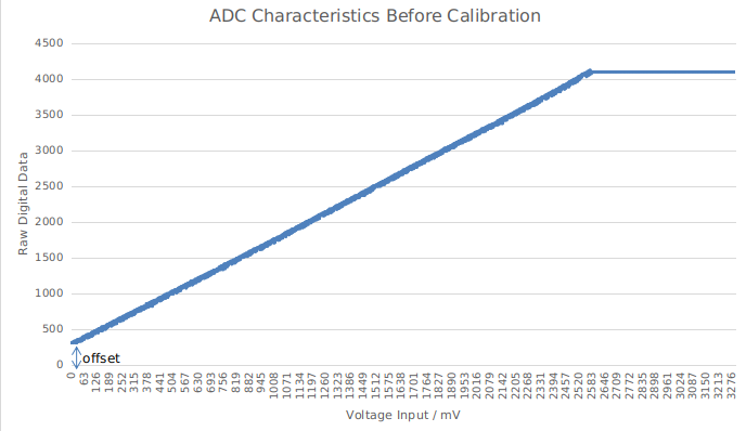
The offset in the uncalibrated characteristics is significant. Step 2 is to correct the offset to 0.
After hardware calibration, the ADC characteristics would be like:
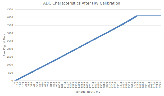
Hardware calibration is done internally by the ADC driver. The consequent results are raw data. A transformation is needed to get the final result, see ADC Conversion.
Software Calibration
To convert ADC raw data to calibrated digital data, following steps should be followed:
Check the eFuse to know if the software calibration is supported via
esp_adc_cal_check_efuse().Calculate the ADC calibration characteristics via
esp_adc_cal_characterize(). The ADC software calibration characteristics are per ADC module and per attenuation. For example, characteristics of ADC1 channel 0 under 11 dB attenuation are the same as characteristics of ADC1 channel 2 under 11 dB attenuation. But characteristics of ADC1 channel 0 under 11 dB attenuation are different with characteristics of ADC2 channel 0 under 11 dB attenuation. Also characteristics of ADC1 channel 0 under 11 dB attenuation are different with characteristics of ADC1 channel 0 under 6 dB attenuation.Get the actual voltage value via
esp_adc_cal_raw_to_voltage().
After software calibration, the ADC characteristics would be like:
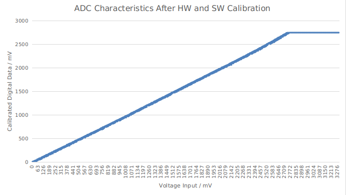
The results provided by the ADC calibration APIs indicate the actual voltage values. ADC software calibration example can be found in peripherals/adc/single_read directory of ESP-IDF examples.
GPIO Lookup Macros
There are macros available to specify the GPIO number of a ADC channel, or vice versa. e.g.
ADC1_CHANNEL_0_GPIO_NUMis the GPIO number of ADC1 channel 0.ADC1_GPIOn_CHANNELis the ADC1 channel number of GPIO n.
API Reference
This reference covers three components:
ADC driver
Header File
Functions
-
void
adc_power_on(void)¶ Enable ADC power.
-
void
adc_power_off(void)¶ Power off SAR ADC.
-
void
adc_power_acquire(void)¶ Increment the usage counter for ADC module. ADC will stay powered on while the counter is greater than 0. Call adc_power_release when done using the ADC.
-
void
adc_power_release(void)¶ Decrement the usage counter for ADC module. ADC will stay powered on while the counter is greater than 0. Call this function when done using the ADC.
-
esp_err_t
adc1_pad_get_io_num(adc1_channel_t channel, gpio_num_t *gpio_num)¶ Get the GPIO number of a specific ADC1 channel.
- Return
ESP_OK if success
ESP_ERR_INVALID_ARG if channel not valid
- Parameters
channel: Channel to get the GPIO numbergpio_num: output buffer to hold the GPIO number
-
esp_err_t
adc1_config_channel_atten(adc1_channel_t channel, adc_atten_t atten)¶ Set the attenuation of a particular channel on ADC1, and configure its associated GPIO pin mux.
The default ADC voltage is for attenuation 0 dB and listed in the table below. By setting higher attenuation it is possible to read higher voltages.
Due to ADC characteristics, most accurate results are obtained within the “suggested range” shown in the following table.
+----------+-------------+-----------------+
|          | attenuation | suggested range |
|    SoC   |     (dB)    |      (mV)       |
+==========+=============+=================+
|          |       0     |    100 ~  950   |
|          +-------------+-----------------+
|          |       2.5   |    100 ~ 1250   |
|   ESP32  +-------------+-----------------+
|          |       6     |    150 ~ 1750   |
|          +-------------+-----------------+
|          |      11     |    150 ~ 2450   |
+----------+-------------+-----------------+
|          |       0     |      0 ~  750   |
|          +-------------+-----------------+
|          |       2.5   |      0 ~ 1050   |
| ESP32-S2 +-------------+-----------------+
|          |       6     |      0 ~ 1300   |
|          +-------------+-----------------+
|          |      11     |      0 ~ 2500   |
+----------+-------------+-----------------+
For maximum accuracy, use the ADC calibration APIs and measure voltages within these recommended ranges.
- Note
For any given channel, this function must be called before the first time
adc1_get_raw()is called for that channel.- Note
This function can be called multiple times to configure multiple ADC channels simultaneously. You may call
adc1_get_raw()only after configuring a channel.- Return
ESP_OK success
ESP_ERR_INVALID_ARG Parameter error
- Parameters
channel: ADC1 channel to configureatten: Attenuation level
-
esp_err_t
adc1_config_width(adc_bits_width_t width_bit)¶ Configure ADC1 capture width, meanwhile enable output invert for ADC1. The configuration is for all channels of ADC1.
- Return
ESP_OK success
ESP_ERR_INVALID_ARG Parameter error
- Parameters
width_bit: Bit capture width for ADC1
-
int
adc1_get_raw(adc1_channel_t channel)¶ Take an ADC1 reading from a single channel.
- Note
ESP32: When the power switch of SARADC1, SARADC2, HALL sensor and AMP sensor is turned on, the input of GPIO36 and GPIO39 will be pulled down for about 80ns. When enabling power for any of these peripherals, ignore input from GPIO36 and GPIO39. Please refer to section 3.11 of ‘ECO_and_Workarounds_for_Bugs_in_ESP32’ for the description of this issue. As a workaround, call adc_power_acquire() in the app. This will result in higher power consumption (by ~1mA), but will remove the glitches on GPIO36 and GPIO39.
- Note
Call
adc1_config_width()before the first time this function is called.- Note
For any given channel, adc1_config_channel_atten(channel) must be called before the first time this function is called. Configuring a new channel does not prevent a previously configured channel from being read.
- Return
-1: Parameter error
Other: ADC1 channel reading.
- Parameters
channel: ADC1 channel to read
-
esp_err_t
adc2_pad_get_io_num(adc2_channel_t channel, gpio_num_t *gpio_num)¶ Get the GPIO number of a specific ADC2 channel.
- Return
ESP_OK if success
ESP_ERR_INVALID_ARG if channel not valid
- Parameters
channel: Channel to get the GPIO numbergpio_num: output buffer to hold the GPIO number
-
esp_err_t
adc2_config_channel_atten(adc2_channel_t channel, adc_atten_t atten)¶ Configure the ADC2 channel, including setting attenuation.
The default ADC voltage is for attenuation 0 dB and listed in the table below. By setting higher attenuation it is possible to read higher voltages.
Due to ADC characteristics, most accurate results are obtained within the “suggested range” shown in the following table.
+----------+-------------+-----------------+
|          | attenuation | suggested range |
|    SoC   |     (dB)    |      (mV)       |
+==========+=============+=================+
|          |       0     |    100 ~  950   |
|          +-------------+-----------------+
|          |       2.5   |    100 ~ 1250   |
|   ESP32  +-------------+-----------------+
|          |       6     |    150 ~ 1750   |
|          +-------------+-----------------+
|          |      11     |    150 ~ 2450   |
+----------+-------------+-----------------+
|          |       0     |      0 ~  750   |
|          +-------------+-----------------+
|          |       2.5   |      0 ~ 1050   |
| ESP32-S2 +-------------+-----------------+
|          |       6     |      0 ~ 1300   |
|          +-------------+-----------------+
|          |      11     |      0 ~ 2500   |
+----------+-------------+-----------------+
For maximum accuracy, use the ADC calibration APIs and measure voltages within these recommended ranges.
- Note
This function also configures the input GPIO pin mux to connect it to the ADC2 channel. It must be called before calling
adc2_get_raw()for this channel.- Note
For any given channel, this function must be called before the first time
adc2_get_raw()is called for that channel.- Return
ESP_OK success
ESP_ERR_INVALID_ARG Parameter error
- Parameters
channel: ADC2 channel to configureatten: Attenuation level
-
esp_err_t
adc2_get_raw(adc2_channel_t channel, adc_bits_width_t width_bit, int *raw_out)¶ Take an ADC2 reading on a single channel.
- Note
ESP32: When the power switch of SARADC1, SARADC2, HALL sensor and AMP sensor is turned on, the input of GPIO36 and GPIO39 will be pulled down for about 80ns. When enabling power for any of these peripherals, ignore input from GPIO36 and GPIO39. Please refer to section 3.11 of ‘ECO_and_Workarounds_for_Bugs_in_ESP32’ for the description of this issue. As a workaround, call adc_power_acquire() in the app. This will result in higher power consumption (by ~1mA), but will remove the glitches on GPIO36 and GPIO39.
- Note
ESP32: For a given channel,
adc2_config_channel_atten()must be called before the first time this function is called. If Wi-Fi is started viaesp_wifi_start(), this function will always fail withESP_ERR_TIMEOUT.- Note
ESP32-S2: ADC2 support hardware arbiter. The arbiter is to improve the use efficiency of ADC2. After the control right is robbed by the high priority, the low priority controller will read the invalid ADC2 data. Default priority: Wi-Fi > RTC > Digital;
- Return
ESP_OK if success
ESP_ERR_TIMEOUT ADC2 is being used by other controller and the request timed out.
ESP_ERR_INVALID_STATE The controller status is invalid. Please try again.
- Parameters
channel: ADC2 channel to readwidth_bit: Bit capture width for ADC2raw_out: the variable to hold the output data.
-
esp_err_t
adc_vref_to_gpio(adc_unit_t adc_unit, gpio_num_t gpio)¶ Output ADC1 or ADC2’s reference voltage to
adc2_channe_t’s IO.This function routes the internal reference voltage of ADCn to one of ADC2’s channels. This reference voltage can then be manually measured for calibration purposes.
- Note
ESP32 only supports output of ADC2’s internal reference voltage.
- Return
ESP_OK: v_ref successfully routed to selected GPIO
ESP_ERR_INVALID_ARG: Unsupported GPIO
- Parameters
[in] adc_unit: ADC unit index[in] gpio: GPIO number (Only ADC2’s channels IO are supported)
-
esp_err_t
adc2_vref_to_gpio(gpio_num_t gpio)¶ Output ADC2 reference voltage to
adc2_channe_t’s IO.This function routes the internal reference voltage of ADCn to one of ADC2’s channels. This reference voltage can then be manually measured for calibration purposes.
- Return
ESP_OK: v_ref successfully routed to selected GPIO
ESP_ERR_INVALID_ARG: Unsupported GPIO
- Parameters
[in] gpio: GPIO number (ADC2’s channels are supported)
-
esp_err_t
adc_digi_initialize(const adc_digi_init_config_t *init_config)¶ Initialize the Digital ADC.
- Return
ESP_ERR_INVALID_ARG If the combination of arguments is invalid.
ESP_ERR_NOT_FOUND No free interrupt found with the specified flags
ESP_ERR_NO_MEM If out of memory
ESP_OK On success
- Parameters
init_config: Pointer to Digital ADC initilization config. Refer toadc_digi_init_config_t.
-
esp_err_t
adc_digi_read_bytes(uint8_t *buf, uint32_t length_max, uint32_t *out_length, uint32_t timeout_ms)¶ Read bytes from Digital ADC through DMA.
- Return
ESP_ERR_INVALID_STATE Driver state is invalid. Usually it means the ADC sampling rate is faster than the task processing rate.
ESP_ERR_TIMEOUT Operation timed out
ESP_OK On success
- Parameters
[out] buf: Buffer to read from ADC.[in] length_max: Expected length of data read from the ADC.[out] out_length: Real length of data read from the ADC via this API.[in] timeout_ms: Time to wait for data via this API, in millisecond.
-
esp_err_t
adc_digi_start(void)¶ Start the Digital ADC and DMA peripherals. After this, the hardware starts working.
- Return
ESP_ERR_INVALID_STATE Driver state is invalid.
ESP_OK On success
-
esp_err_t
adc_digi_stop(void)¶ Stop the Digital ADC and DMA peripherals. After this, the hardware stops working.
- Return
ESP_ERR_INVALID_STATE Driver state is invalid.
ESP_OK On success
-
esp_err_t
adc_digi_deinitialize(void)¶ Deinitialize the Digital ADC.
- Return
ESP_ERR_INVALID_STATE Driver state is invalid.
ESP_OK On success
-
esp_err_t
adc_digi_controller_configure(const adc_digi_configuration_t *config)¶ Setting the digital controller.
- Return
ESP_ERR_INVALID_STATE Driver state is invalid.
ESP_ERR_INVALID_ARG If the combination of arguments is invalid.
ESP_OK On success
- Parameters
config: Pointer to digital controller paramter. Refer toadc_digi_config_t.
-
esp_err_t
adc_digi_filter_reset(adc_digi_filter_idx_t idx)¶ Reset adc digital controller filter.
- Return
ESP_OK Success
- Parameters
idx: Filter index.
-
esp_err_t
adc_digi_filter_set_config(adc_digi_filter_idx_t idx, adc_digi_filter_t *config)¶ Set adc digital controller filter configuration.
- Note
For ESP32S2, Filter IDX0/IDX1 can only be used to filter all enabled channels of ADC1/ADC2 unit at the same time.
- Return
ESP_OK Success
- Parameters
idx: Filter index.config: Seeadc_digi_filter_t.
-
esp_err_t
adc_digi_filter_get_config(adc_digi_filter_idx_t idx, adc_digi_filter_t *config)¶ Get adc digital controller filter configuration.
- Note
For ESP32S2, Filter IDX0/IDX1 can only be used to filter all enabled channels of ADC1/ADC2 unit at the same time.
- Return
ESP_OK Success
- Parameters
idx: Filter index.config: Seeadc_digi_filter_t.
-
esp_err_t
adc_digi_filter_enable(adc_digi_filter_idx_t idx, bool enable)¶ Enable/disable adc digital controller filter. Filtering the ADC data to obtain smooth data at higher sampling rates.
- Note
For ESP32S2, Filter IDX0/IDX1 can only be used to filter all enabled channels of ADC1/ADC2 unit at the same time.
- Return
ESP_OK Success
- Parameters
idx: Filter index.enable: Enable/Disable filter.
-
esp_err_t
adc_digi_monitor_set_config(adc_digi_monitor_idx_t idx, adc_digi_monitor_t *config)¶ Config monitor of adc digital controller.
- Note
For ESP32S2, The monitor will monitor all the enabled channel data of the each ADC unit at the same time.
- Return
ESP_OK Success
- Parameters
idx: Monitor index.config: Seeadc_digi_monitor_t.
-
esp_err_t
adc_digi_monitor_enable(adc_digi_monitor_idx_t idx, bool enable)¶ Enable/disable monitor of adc digital controller.
- Note
For ESP32S2, The monitor will monitor all the enabled channel data of the each ADC unit at the same time.
- Return
ESP_OK Success
- Parameters
idx: Monitor index.enable: True or false enable monitor.
Structures
-
struct
adc_digi_init_config_s¶ ADC DMA driver configuration.
Public Members
-
uint32_t
max_store_buf_size¶ Max length of the converted data that driver can store before they are processed.
-
uint32_t
conv_num_each_intr¶ Bytes of data that can be converted in 1 interrupt.
-
uint32_t
adc1_chan_mask¶ Channel list of ADC1 to be initialized.
-
uint32_t
adc2_chan_mask¶ Channel list of ADC2 to be initialized.
-
uint32_t
-
struct
adc_digi_configuration_t¶ ADC digital controller settings.
Public Members
-
bool
conv_limit_en¶ To limit ADC conversion times. Conversion stops after finishing
conv_limit_numtimes conversion.
-
uint32_t
conv_limit_num¶ Set the upper limit of the number of ADC conversion triggers. Range: 1 ~ 255.
-
uint32_t
pattern_num¶ Number of ADC channels that will be used.
-
adc_digi_pattern_config_t *
adc_pattern¶ List of configs for each ADC channel that will be used.
-
uint32_t
sample_freq_hz¶ The expected ADC sampling frequency in Hz. Range: 611Hz ~ 83333Hz Fs = Fd / interval / 2 Fs: sampling frequency; Fd: digital controller frequency, no larger than 5M for better performance interval: interval between 2 measurement trigger signal, the smallest interval should not be smaller than the ADC measurement period, the largest interval should not be larger than 4095
-
adc_digi_convert_mode_t
conv_mode¶ ADC DMA conversion mode, see
adc_digi_convert_mode_t.
-
adc_digi_output_format_t
format¶ ADC DMA conversion output format, see
adc_digi_output_format_t.
-
bool
Macros
-
ADC_ATTEN_0db¶ ADC rtc controller attenuation option.
- Note
This definitions are only for being back-compatible
-
ADC_ATTEN_2_5db
-
ADC_ATTEN_6db
-
ADC_ATTEN_11db
-
ADC_WIDTH_BIT_DEFAULT¶ The default (max) bit width of the ADC of current version. You can also get the maximum bitwidth by
SOC_ADC_MAX_BITWIDTHdefined in soc_caps.h.
-
ADC_WIDTH_9Bit
-
ADC_WIDTH_10Bit
-
ADC_WIDTH_11Bit
-
ADC_WIDTH_12Bit
-
ADC_MAX_DELAY¶ Digital ADC DMA read max timeout value, it may make the
adc_digi_read_bytesblock forever if the OS supports.
Type Definitions
-
typedef struct adc_digi_init_config_s
adc_digi_init_config_t¶ ADC DMA driver configuration.
Enumerations
Header File
Structures
-
struct
adc_digi_pattern_config_t¶ ADC digital controller pattern configuration.
-
struct
adc_digi_output_data_t¶ ADC digital controller (DMA mode) output data format. Used to analyze the acquired ADC (DMA) data.
Public Members
-
uint32_t
data: 12¶ ADC real output data info. Resolution: 12 bit.
-
uint32_t
reserved12: 1¶ Reserved12.
-
uint32_t
channel: 3¶ ADC channel index info. If (channel < ADC_CHANNEL_MAX), The data is valid. If (channel > ADC_CHANNEL_MAX), The data is invalid.
-
uint32_t
unit: 1¶ ADC unit index info. 0: ADC1; 1: ADC2.
-
uint32_t
reserved17_31: 15¶ Reserved17.
-
struct adc_digi_output_data_t::[anonymous]::[anonymous]
type2¶ When the configured output format is 12bit.
ADC_DIGI_FORMAT_11BIT
-
uint32_t
val¶ Raw data value
-
uint32_t
-
struct
adc_arbiter_t¶ ADC arbiter work mode and priority setting.
- Note
ESP32-S2: Only ADC2 support arbiter.
Public Members
-
adc_arbiter_mode_t
mode¶ Refer to
adc_arbiter_mode_t. Note: only support ADC2.
-
uint8_t
rtc_pri¶ RTC controller priority. Range: 0 ~ 2.
-
uint8_t
dig_pri¶ Digital controller priority. Range: 0 ~ 2.
-
uint8_t
pwdet_pri¶ Wi-Fi controller priority. Range: 0 ~ 2.
-
struct
adc_digi_filter_t¶ ADC digital controller (DMA mode) filter configuration.
- Note
For ESP32-S2, The filter object of the ADC is fixed.
- Note
For ESP32-S2, The filter object is always all enabled channels.
Public Members
-
adc_unit_t
adc_unit¶ Set adc unit number for filter. For ESP32-S2, Filter IDX0/IDX1 can only be used to filter all enabled channels of ADC1/ADC2 unit at the same time.
-
adc_channel_t
channel¶ Set adc channel number for filter. For ESP32-S2, it’s always
ADC_CHANNEL_MAX
-
adc_digi_filter_mode_t
mode¶ Set adc filter mode for filter. See
adc_digi_filter_mode_t.
-
struct
adc_digi_monitor_t¶ ADC digital controller (DMA mode) monitor configuration.
- Note
For ESP32-S2, The monitor object of the ADC is fixed.
- Note
For ESP32-S2, The monitor object is always all enabled channels.
Public Members
-
adc_unit_t
adc_unit¶ Set adc unit number for monitor. For ESP32-S2, monitor IDX0/IDX1 can only be used to monitor all enabled channels of ADC1/ADC2 unit at the same time.
-
adc_channel_t
channel¶ Set adc channel number for monitor. For ESP32-S2, it’s always
ADC_CHANNEL_MAX
-
adc_digi_monitor_mode_t
mode¶ Set adc monitor mode. See
adc_digi_monitor_mode_t.
-
uint32_t
h_threshold¶ Set monitor threshold of adc digital controller.
-
uint32_t
l_threshold¶ Set monitor threshold of adc digital controller.
Macros
-
ADC_ARBITER_CONFIG_DEFAULT()¶ ADC arbiter default configuration.
- Note
ESP32S2: Only ADC2 supports (needs) an arbiter.
Enumerations
-
enum
adc_unit_t¶ ADC unit enumeration.
- Note
For ADC digital controller (DMA mode), ESP32 doesn’t support
ADC_UNIT_2,ADC_UNIT_BOTH,ADC_UNIT_ALTER.
Values:
-
ADC_UNIT_1= 1¶ SAR ADC 1.
-
ADC_UNIT_2= 2¶ SAR ADC 2.
-
ADC_UNIT_BOTH= 3¶ SAR ADC 1 and 2.
-
ADC_UNIT_ALTER= 7¶ SAR ADC 1 and 2 alternative mode.
-
ADC_UNIT_MAX
-
enum
adc_channel_t¶ ADC channels handle. See
adc1_channel_t,adc2_channel_t.- Note
For ESP32 ADC1, don’t use
ADC_CHANNEL_8,ADC_CHANNEL_9. Seeadc1_channel_t.
Values:
-
ADC_CHANNEL_0= 0¶ ADC channel
-
ADC_CHANNEL_1¶ ADC channel
-
ADC_CHANNEL_2¶ ADC channel
-
ADC_CHANNEL_3¶ ADC channel
-
ADC_CHANNEL_4¶ ADC channel
-
ADC_CHANNEL_5¶ ADC channel
-
ADC_CHANNEL_6¶ ADC channel
-
ADC_CHANNEL_7¶ ADC channel
-
ADC_CHANNEL_8¶ ADC channel
-
ADC_CHANNEL_9¶ ADC channel
-
ADC_CHANNEL_MAX
-
enum
adc_atten_t¶ ADC attenuation parameter. Different parameters determine the range of the ADC. See
adc1_config_channel_atten.Values:
-
ADC_ATTEN_DB_0= 0¶ No input attenumation, ADC can measure up to approx. 800 mV.
-
ADC_ATTEN_DB_2_5= 1¶ The input voltage of ADC will be attenuated extending the range of measurement by about 2.5 dB (1.33 x)
-
ADC_ATTEN_DB_6= 2¶ The input voltage of ADC will be attenuated extending the range of measurement by about 6 dB (2 x)
-
ADC_ATTEN_DB_11= 3¶ The input voltage of ADC will be attenuated extending the range of measurement by about 11 dB (3.55 x)
-
ADC_ATTEN_MAX
-
-
enum
adc_bits_width_t¶ ADC resolution setting option.
- Note
Only used in single read mode
Values:
-
ADC_WIDTH_BIT_12= 3¶ ADC capture width is 12Bit.
-
ADC_WIDTH_MAX
-
enum
adc_digi_convert_mode_t¶ ADC digital controller (DMA mode) work mode.
Values:
-
ADC_CONV_SINGLE_UNIT_1= 1¶ Only use ADC1 for conversion.
-
ADC_CONV_SINGLE_UNIT_2= 2¶ Only use ADC2 for conversion.
-
ADC_CONV_BOTH_UNIT= 3¶ Use Both ADC1 and ADC2 for conversion simultaneously.
-
ADC_CONV_ALTER_UNIT= 7¶ Use both ADC1 and ADC2 for conversion by turn. e.g. ADC1 -> ADC2 -> ADC1 -> ADC2 …..
-
ADC_CONV_UNIT_MAX
-
-
enum
adc_digi_output_format_t¶ ADC digital controller (DMA mode) output data format option.
Values:
-
ADC_DIGI_FORMAT_12BIT¶ ADC to DMA data format, [15:12]-channel, [11: 0]-12 bits ADC data (
adc_digi_output_data_t). Note: For single convert mode.
-
ADC_DIGI_FORMAT_11BIT¶ ADC to DMA data format, [15]-adc unit, [14:11]-channel, [10: 0]-11 bits ADC data (
adc_digi_output_data_t). Note: For multi or alter convert mode.
-
ADC_DIGI_FORMAT_MAX
-
ADC_DIGI_OUTPUT_FORMAT_TYPE1¶ See
adc_digi_output_data_t.type1
-
ADC_DIGI_OUTPUT_FORMAT_TYPE2
-
-
enum
adc_arbiter_mode_t¶ ADC arbiter work mode option.
- Note
ESP32-S2: Only ADC2 support arbiter.
Values:
-
ADC_ARB_MODE_SHIELD¶ Force shield arbiter, Select the highest priority controller to work.
-
ADC_ARB_MODE_FIX¶ Fixed priority switch controller mode.
-
ADC_ARB_MODE_LOOP¶ Loop priority switch controller mode. Each controller has the same priority, and the arbiter will switch to the next controller after the measurement is completed.
-
enum
adc_digi_filter_idx_t¶ ADC digital controller (DMA mode) filter index options.
- Note
For ESP32-S2, The filter object of the ADC is fixed.
Values:
-
ADC_DIGI_FILTER_IDX0= 0¶ The filter index 0. For ESP32-S2, It can only be used to filter all enabled channels of ADC1 unit at the same time.
-
ADC_DIGI_FILTER_IDX1¶ The filter index 1. For ESP32-S2, It can only be used to filter all enabled channels of ADC2 unit at the same time.
-
ADC_DIGI_FILTER_IDX_MAX
-
enum
adc_digi_filter_mode_t¶ ADC digital controller (DMA mode) filter type options. Expression: filter_data = (k-1)/k * last_data + new_data / k.
Values:
-
ADC_DIGI_FILTER_DIS= -1¶ Disable filter
-
ADC_DIGI_FILTER_IIR_2= 0¶ The filter mode is first-order IIR filter. The coefficient is 2.
-
ADC_DIGI_FILTER_IIR_4¶ The filter mode is first-order IIR filter. The coefficient is 4.
-
ADC_DIGI_FILTER_IIR_8¶ The filter mode is first-order IIR filter. The coefficient is 8.
-
ADC_DIGI_FILTER_IIR_16¶ The filter mode is first-order IIR filter. The coefficient is 16.
-
ADC_DIGI_FILTER_IIR_64¶ The filter mode is first-order IIR filter. The coefficient is 64.
-
ADC_DIGI_FILTER_IIR_MAX
-
-
enum
adc_digi_monitor_idx_t¶ ADC digital controller (DMA mode) monitor index options.
- Note
For ESP32-S2, The monitor object of the ADC is fixed.
Values:
-
ADC_DIGI_MONITOR_IDX0= 0¶ The monitor index 0. For ESP32-S2, It can only be used to monitor all enabled channels of ADC1 unit at the same time.
-
ADC_DIGI_MONITOR_IDX1¶ The monitor index 1. For ESP32-S2, It can only be used to monitor all enabled channels of ADC2 unit at the same time.
-
ADC_DIGI_MONITOR_IDX_MAX
-
enum
adc_digi_monitor_mode_t¶ Set monitor mode of adc digital controller. MONITOR_HIGH:If ADC_OUT > threshold, Generates monitor interrupt. MONITOR_LOW: If ADC_OUT < threshold, Generates monitor interrupt.
Values:
-
ADC_DIGI_MONITOR_DIS= 0¶ Disable monitor.
-
ADC_DIGI_MONITOR_EN¶ If ADC_OUT < threshold, Generates monitor interrupt. If ADC_OUT > threshold, Generates monitor interrupt.
-
ADC_DIGI_MONITOR_MAX
-
ADC Calibration
Header File
Functions
-
esp_err_t
esp_adc_cal_check_efuse(esp_adc_cal_value_t value_type)¶ Checks if ADC calibration values are burned into eFuse.
This function checks if ADC reference voltage or Two Point values have been burned to the eFuse of the current ESP32
- Note
in ESP32S2, only ESP_ADC_CAL_VAL_EFUSE_TP is supported. Some old ESP32S2s do not support this, either. In which case you have to calibrate it manually, possibly by performing your own two-point calibration on the chip.
- Return
ESP_OK: The calibration mode is supported in eFuse
ESP_ERR_NOT_SUPPORTED: Error, eFuse values are not burned
ESP_ERR_INVALID_ARG: Error, invalid argument (ESP_ADC_CAL_VAL_DEFAULT_VREF)
- Parameters
value_type: Type of calibration value (ESP_ADC_CAL_VAL_EFUSE_VREF or ESP_ADC_CAL_VAL_EFUSE_TP)
-
esp_adc_cal_value_t
esp_adc_cal_characterize(adc_unit_t adc_num, adc_atten_t atten, adc_bits_width_t bit_width, uint32_t default_vref, esp_adc_cal_characteristics_t *chars)¶ Characterize an ADC at a particular attenuation.
This function will characterize the ADC at a particular attenuation and generate the ADC-Voltage curve in the form of [y = coeff_a * x + coeff_b]. Characterization can be based on Two Point values, eFuse Vref, or default Vref and the calibration values will be prioritized in that order.
- Note
For ESP32, Two Point values and eFuse Vref calibration can be enabled/disabled using menuconfig. For ESP32s2, only Two Point values calibration and only ADC_WIDTH_BIT_13 is supported. The parameter default_vref is unused.
- Return
ESP_ADC_CAL_VAL_EFUSE_VREF: eFuse Vref used for characterization
ESP_ADC_CAL_VAL_EFUSE_TP: Two Point value used for characterization (only in Linear Mode)
ESP_ADC_CAL_VAL_DEFAULT_VREF: Default Vref used for characterization
- Parameters
[in] adc_num: ADC to characterize (ADC_UNIT_1 or ADC_UNIT_2)[in] atten: Attenuation to characterize[in] bit_width: Bit width configuration of ADC[in] default_vref: Default ADC reference voltage in mV (Only in ESP32, used if eFuse values is not available)[out] chars: Pointer to empty structure used to store ADC characteristics
-
uint32_t
esp_adc_cal_raw_to_voltage(uint32_t adc_reading, const esp_adc_cal_characteristics_t *chars)¶ Convert an ADC reading to voltage in mV.
This function converts an ADC reading to a voltage in mV based on the ADC’s characteristics.
- Note
Characteristics structure must be initialized before this function is called (call esp_adc_cal_characterize())
- Return
Voltage in mV
- Parameters
[in] adc_reading: ADC reading[in] chars: Pointer to initialized structure containing ADC characteristics
-
esp_err_t
esp_adc_cal_get_voltage(adc_channel_t channel, const esp_adc_cal_characteristics_t *chars, uint32_t *voltage)¶ Reads an ADC and converts the reading to a voltage in mV.
This function reads an ADC then converts the raw reading to a voltage in mV based on the characteristics provided. The ADC that is read is also determined by the characteristics.
- Note
The Characteristics structure must be initialized before this function is called (call esp_adc_cal_characterize())
- Return
ESP_OK: ADC read and converted to mV
ESP_ERR_INVALID_ARG: Error due to invalid arguments
ESP_ERR_INVALID_STATE: Reading result is invalid. Try to read again.
- Parameters
[in] channel: ADC Channel to read[in] chars: Pointer to initialized ADC characteristics structure[out] voltage: Pointer to store converted voltage
Structures
-
struct
esp_adc_cal_characteristics_t¶ Structure storing characteristics of an ADC.
- Note
Call esp_adc_cal_characterize() to initialize the structure
Public Members
-
adc_unit_t
adc_num¶ ADC number
-
adc_atten_t
atten¶ ADC attenuation
-
adc_bits_width_t
bit_width¶ ADC bit width
-
uint32_t
coeff_a¶ Gradient of ADC-Voltage curve
-
uint32_t
coeff_b¶ Offset of ADC-Voltage curve
-
uint32_t
vref¶ Vref used by lookup table
-
const uint32_t *
low_curve¶ Pointer to low Vref curve of lookup table (NULL if unused)
-
const uint32_t *
high_curve¶ Pointer to high Vref curve of lookup table (NULL if unused)
-
uint8_t
version¶ ADC Calibration
Enumerations
-
enum
esp_adc_cal_value_t¶ Type of calibration value used in characterization.
Values:
-
ESP_ADC_CAL_VAL_EFUSE_VREF= 0¶ Characterization based on reference voltage stored in eFuse
-
ESP_ADC_CAL_VAL_EFUSE_TP= 1¶ Characterization based on Two Point values stored in eFuse
-
ESP_ADC_CAL_VAL_DEFAULT_VREF= 2¶ Characterization based on default reference voltage
-
ESP_ADC_CAL_VAL_EFUSE_TP_FIT= 3¶ Characterization based on Two Point values and fitting curve coefficients stored in eFuse
-
ESP_ADC_CAL_VAL_MAX
-
ESP_ADC_CAL_VAL_NOT_SUPPORTED= ESP_ADC_CAL_VAL_MAX
-