ESP-Modbus
Overview
The Modbus serial communication protocol is de facto standard protocol widely used to connect industrial electronic devices. Modbus allows communication among many devices connected to the same network, for example, a system that measures temperature and humidity and communicates the results to a computer. The Modbus protocol uses several types of data: Holding Registers, Input Registers, Coils (single bit output), Discrete Inputs. Versions of the Modbus protocol exist for serial port and for Ethernet and other protocols that support the Internet protocol suite. There are many variants of Modbus protocols, some of them are:
Modbus RTU— This is used in serial communication and makes use of a compact, binary representation of the data for protocol communication. The RTU format follows the commands/data with a cyclic redundancy check checksum as an error check mechanism to ensure the reliability of data. Modbus RTU is the most common implementation available for Modbus. A Modbus RTU message must be transmitted continuously without inter-character hesitations. Modbus messages are framed (separated) by idle (silent) periods. The RS-485 interface communication is usually used for this type.
Modbus ASCII— This is used in serial communication and makes use of ASCII characters for protocol communication. The ASCII format uses a longitudinal redundancy check checksum. Modbus ASCII messages are framed by leading colon (“:”) and trailing newline (CR/LF).
Modbus TCP/IP or Modbus TCP— This is a Modbus variant used for communications over TCP/IP networks, connecting over port 502. It does not require a checksum calculation, as lower layers already provide checksum protection.
The following document (and included code snippets) requires some familiarity with the Modbus protocol. Refer to the Modbus Organization’s with protocol specifications for specifics.
Messaging Model And Data Mapping
Modbus is an application protocol that defines rules for messaging structure and data organization that are independent of the data transmission medium. Traditional serial Modbus is a register-based protocol that defines message transactions that occur between master(s) and slave devices (multiple masters are allowed on using Modbus TCP/IP). The slave devices listen for communication from the master and simply respond as instructed. The master(s) always controls communication and may communicate directly to one slave, or all connected slaves, but the slaves cannot communicate directly with each other.
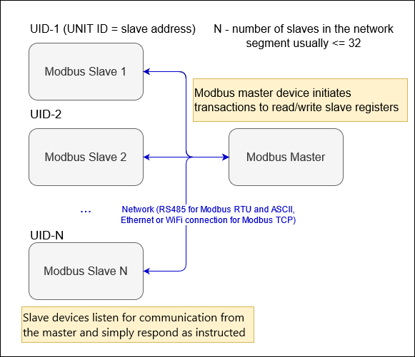
Modbus segment diagram
Note
It is assumed that the number of slaves and their register maps are known by the Modbus master before the start of stack.
The register map of each slave device is usually part of its device manual. A Slave device usually permits configuration of its short slave address and communication options that are used within the device’s network segment.
The Modbus protocol allows devices to map data to four types of registers (Holding, Input, Discrete, Coil). The figure below illustrates an example mapping of a device’s data to the four types of registers.
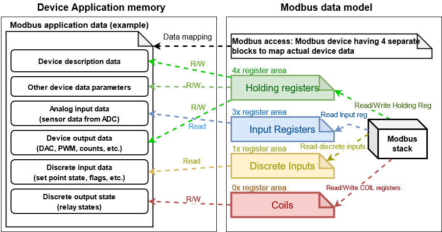
Modbus data mapping
The following sections give an overview of how to use the ESP_Modbus component found under components/freemodbus. The sections cover initialization of a Modbus port, and the setup a master or slave device accordingly:
Modbus Port Initialization
The ESP_Modbus supports Modbus SERIAL and TCP ports and a port must be initialized before calling any other Modbus API. The functions below are used to create and then initialize Modbus controller interface (either master or slave) over a particular transmission medium (either Serial or TCP/IP):
The API call uses the first parameter to recognize the type of port being initialized. Supported enumeration for different ports: MB_PORT_SERIAL_MASTER, MB_PORT_SERIAL_SLAVE accordingly.
The parameters MB_PORT_TCP_MASTER, MB_PORT_TCP_SLAVE are reserved for internal usage.
void* master_handler = NULL; // Pointer to allocate interface structure
// Initialization of Modbus master for serial port
esp_err_t err = mbc_master_init(MB_PORT_SERIAL_MASTER, &master_handler);
if (master_handler == NULL || err != ESP_OK) {
    ESP_LOGE(TAG, "mb controller initialization fail.");
}
This example code to initialize slave port:
void* slave_handler = NULL; // Pointer to allocate interface structure
// Initialization of Modbus slave for TCP
esp_err_t err = mbc_slave_init_tcp(&slave_handler);
if (slave_handler == NULL || err != ESP_OK) {
    // Error handling is performed here
    ESP_LOGE(TAG, "mb controller initialization fail.");
}
Modbus Master API Overview
The following overview describes how to setup Modbus master communication. The overview reflects a typical programming workflow and is broken down into the sections provided below:
Modbus Port Initialization - Initialization of Modbus controller interface for the selected port.
Configuring Master Data Access - Configure data descriptors to access slave parameters.
Master Communication Options - Allows to setup communication options for selected port.
Master Communication - Start stack and sending / receiving data.
Modbus Master Teardown - Destroy Modbus controller and its resources.
Configuring Master Data Access
The architectural approach of ESP_Modbus includes one level above standard Modbus IO driver. The additional layer is called Modbus controller and its goal is to add an abstraction such as CID - characteristic identifier. The CID is linked to a corresponding Modbus registers through the table called Data Dictionary and represents device physical parameter (such as temperature, humidity, etc.) in specific Modbus slave device. This approach allows the upper layer (e.g., MESH or MQTT) to be isolated from Modbus specifics thus simplify Modbus integration with other protocols/networks.
The Data Dictionary is the list in the Modbus master which shall be defined by user to link each CID to its corresponding Modbus registers representation using Register Mapping table of the Modbus slave being used.
Each element in this data dictionary is of type mb_parameter_descriptor_t and represents the description of one physical characteristic:
Field |
Description |
Detailed information |
|---|---|---|
|
Characteristic ID |
The identifier of characteristic (must be unique). |
|
Characteristic Name |
String description of the characteristic. |
|
Characteristic Units |
Physical Units of the characteristic. |
|
Modbus Slave Address |
The short address of the device with correspond parameter UID. |
|
Modbus Register Type |
Type of Modbus register area.
|
|
Modbus Register Start |
Relative register address of the characteristic in the register area. |
|
Modbus Register Size |
Length of characteristic in registers. |
|
Instance Offset |
Offset to instance of the characteristic in bytes. It is used to calculate the absolute address to the characteristic in the storage structure. It is optional field and can be set to zero if the parameter is not used in the application. |
|
Data Type |
Specifies type of the characteristic.
|
|
Data Size |
The storage size of the characteristic (bytes). |
|
Parameter Options |
Limits, options of characteristic used during processing of alarm in user application (optional) |
|
Parameter access type |
Can be used in user application to define the behavior of the characteristic during processing of data in user application;
|
Note
The cid and param_key have to be unique. Please use the prefix to the parameter key if you have several similar parameters in your register map table.
CID |
Register |
Length |
Range |
Type |
Units |
Description |
|---|---|---|---|---|---|---|
0 |
30000 |
4 |
MAX_UINT |
U32 |
Not defined |
Serial number of device (4 bytes) read-only |
1 |
30002 |
2 |
MAX_UINT |
U16 |
Not defined |
Software version (4 bytes) read-only |
2 |
40000 |
4 |
-20..40 |
FLOAT |
DegC |
Room temperature in DegC. Writing a temperature value to this register for single point calibration. |
// Enumeration of modbus slave addresses accessed by master device
enum {
    MB_DEVICE_ADDR1 = 1,
    MB_DEVICE_ADDR2,
    MB_SLAVE_COUNT
};

// Enumeration of all supported CIDs for device
enum {
    CID_SER_NUM1 = 0,
    CID_SW_VER1,
    CID_TEMP_DATA_1,
    CID_SER_NUM2,
    CID_SW_VER2,
    CID_TEMP_DATA_2
};

// Example Data Dictionary for Modbus parameters in 2 slaves in the segment
mb_parameter_descriptor_t device_parameters[] = {
    // CID, Name, Units, Modbus addr, register type, Modbus Reg Start Addr, Modbus Reg read length,
    // Instance offset (NA), Instance type, Instance length (bytes), Options (NA), Permissions
    { CID_SER_NUM1, STR("Serial_number_1"), STR("--"), MB_DEVICE_ADDR1, MB_PARAM_INPUT, 0, 2,
                    0, PARAM_TYPE_U32, 4, OPTS( 0,0,0 ), PAR_PERMS_READ_WRITE_TRIGGER },
    { CID_SW_VER1, STR("Software_version_1"), STR("--"), MB_DEVICE_ADDR1, MB_PARAM_INPUT, 2, 1,
                    0, PARAM_TYPE_U16, 2, OPTS( 0,0,0 ), PAR_PERMS_READ_WRITE_TRIGGER },
    { CID_TEMP_DATA_1, STR("Temperature_1"), STR("C"), MB_DEVICE_ADDR1, MB_PARAM_HOLDING, 0, 2,
                    0, PARAM_TYPE_FLOAT, 4, OPTS( 16, 30, 1 ), PAR_PERMS_READ_WRITE_TRIGGER },
    { CID_SER_NUM2, STR("Serial_number_2"), STR("--"), MB_DEVICE_ADDR2, MB_PARAM_INPUT, 0, 2,
                    0, PARAM_TYPE_U32, 4, OPTS( 0,0,0 ), PAR_PERMS_READ_WRITE_TRIGGER },
    { CID_SW_VER2, STR("Software_version_2"), STR("--"), MB_DEVICE_ADDR2, MB_PARAM_INPUT, 2, 1,
                    0, PARAM_TYPE_U16, 2, OPTS( 0,0,0 ), PAR_PERMS_READ_WRITE_TRIGGER },
    { CID_TEMP_DATA_2, STR("Temperature_2"), STR("C"), MB_DEVICE_ADDR2, MB_PARAM_HOLDING, 0, 2,
                    0, PARAM_TYPE_FLOAT, 4, OPTS( 20, 30, 1 ), PAR_PERMS_READ_WRITE_TRIGGER },
};
// Calculate number of parameters in the table
uint16_t num_device_parameters = (sizeof(device_parameters) / sizeof(device_parameters[0]));
During initialization of the Modbus stack, a pointer to the Data Dictionary (called descriptor) must be provided as the parameter of the function below.
mbc_master_set_descriptor(): Initialization of master descriptor.
ESP_ERROR_CHECK(mbc_master_set_descriptor(&device_parameters[0], num_device_parameters));
The Data Dictionary can be initialized from SD card, MQTT or other source before start of stack. Once the initialization and setup is done, the Modbus controller allows the reading of complex parameters from any slave included in descriptor table using its CID.
Master Communication Options
Calling the setup function allows for specific communication options to be defined for port.
The communication structure provided as a parameter is different for serial and TCP communication mode.
Example setup for serial port:
mb_communication_info_t comm_info = {
    .port = MB_PORT_NUM,        // Serial port number
    .mode = MB_MODE_RTU,        // Modbus mode of communication (MB_MODE_RTU or MB_MODE_ASCII)
    .baudrate = 9600,           // Modbus communication baud rate
    .parity = MB_PARITY_NONE    // parity option for serial port
};

ESP_ERROR_CHECK(mbc_master_setup((void*)&comm_info));
Modbus master TCP port requires additional definition of IP address table where number of addresses should be equal to number of unique slave addresses in master Modbus Data Dictionary:
The order of IP address string corresponds to short slave address in the Data Dictionary.
#define MB_SLAVE_COUNT 2 // Number of slaves in the segment being accessed (as defined in Data Dictionary)

char* slave_ip_address_table[MB_SLAVE_COUNT] = {
    "192.168.1.2",     // Address corresponds to UID1 and set to predefined value by user
    "192.168.1.3",     // corresponds to UID2 in the segment
    NULL               // end of table
};

mb_communication_info_t comm_info = {
    .ip_port = MB_TCP_PORT,                    // Modbus TCP port number (default = 502)
    .ip_addr_type = MB_IPV4,                   // version of IP protocol
    .ip_mode = MB_MODE_TCP,                    // Port communication mode
    .ip_addr = (void*)slave_ip_address_table,  // assign table of IP addresses
    .ip_netif_ptr = esp_netif_ptr              // esp_netif_ptr pointer to the corresponding network interface
};

ESP_ERROR_CHECK(mbc_master_setup((void*)&comm_info));
Note
Refer to esp_netif component for more information about network interface initialization.
The slave IP addresses in the table can be assigned automatically using mDNS service as described in the example. Refer to protocols/modbus/tcp/mb_tcp_master for more information.
Note
RS485 communication requires call to UART specific APIs to setup communication mode and pins. Refer to Running UART Communication section of UART documentation.
Master Communication
The starting of the Modbus controller is the final step in enabling communication. This is performed using function below:
esp_err_t err = mbc_master_start();
if (err != ESP_OK) {
    ESP_LOGE(TAG, "mb controller start fail, err=%x.", err);
}
The list of functions below are used by the Modbus master stack from a user’s application:
mbc_master_send_request(): This function executes a blocking Modbus request. The master sends a data request (as defined in parameter request structure mb_param_request_t) and then blocks until a response from corresponding slave and returns the status of command execution. This function provides a standard way for read/write access to Modbus devices in the network.
mbc_master_get_cid_info(): The function gets information about each characteristic supported in the data dictionary and returns the characteristic’s description in the form of the mb_parameter_descriptor_t structure. Each characteristic is accessed using its CID.
mbc_master_get_parameter(): The function reads the data of a characteristic defined in the parameters of a Modbus slave device. The additional data for request is taken from parameter description table.
Example:
const mb_parameter_descriptor_t* param_descriptor = NULL;
uint8_t temp_data[4] = {0}; // temporary buffer to hold maximum CID size
uint8_t type = 0;
....
// Get the information for characteristic cid from data dictionary
esp_err_t err = mbc_master_get_cid_info(cid, ¶m_descriptor);
if ((err != ESP_ERR_NOT_FOUND) && (param_descriptor != NULL)) {
err = mbc_master_get_parameter(param_descriptor->cid, (char*)param_descriptor->param_key, (uint8_t*)temp_data, &type);
if (err == ESP_OK) {
ESP_LOGI(TAG, "Characteristic #%d %s (%s) value = (0x%08x) read successful.",
param_descriptor->cid,
(char*)param_descriptor->param_key,
(char*)param_descriptor->param_units,
*(uint32_t*)temp_data);
} else {
ESP_LOGE(TAG, "Characteristic #%d (%s) read fail, err = 0x%x (%s).",
param_descriptor->cid,
(char*)param_descriptor->param_key,
(int)err,
(char*)esp_err_to_name(err));
}
} else {
ESP_LOGE(TAG, "Could not get information for characteristic %d.", cid);
}
The function writes characteristic’s value defined as a name and cid parameter in corresponded slave device. The additional data for parameter request is taken from master parameter description table.
uint8_t type = 0; // Type of parameter
uint8_t temp_data[4] = {0}; // temporary buffer

esp_err_t err = mbc_master_set_parameter(CID_TEMP_DATA_2, "Temperature_2", (uint8_t*)temp_data, &type);
if (err == ESP_OK) {
    ESP_LOGI(TAG, "Set parameter data successfully.");
} else {
    ESP_LOGE(TAG, "Set data fail, err = 0x%x (%s).", (int)err, (char*)esp_err_to_name(err));
}
Modbus Master Teardown
This function stops Modbus communication stack and destroys controller interface and free all used active objects.
ESP_ERROR_CHECK(mbc_master_destroy());
Modbus Slave API Overview
The sections below represent typical programming workflow for the slave API which should be called in following order:
Modbus Port Initialization - Initialization of Modbus controller interface for the selected port.
Configuring Slave Data Access - Configure data descriptors to access slave parameters.
Slave Communication Options - Allows to setup communication options for selected port.
Slave Communication - Start stack and sending / receiving data. Filter events when master accesses the register areas.
Modbus Slave Teardown - Destroy Modbus controller and its resources.
Configuring Slave Data Access
The following functions must be called when the Modbus controller slave port is already initialized. Refer to Modbus Port Initialization.
The slave stack requires the user to define structures (memory storage areas) that store the Modbus parameters accessed by stack. These structures should be prepared by the user and be assigned to the Modbus controller interface using mbc_slave_set_descriptor() API call before the start of communication. The slave task can call the mbc_slave_check_event() function which will block until the Modbus master access the slave. The slave task can then get information about the data being accessed.
Note
One slave can define several area descriptors per each type of Modbus register area with different start_offset.
Register area is defined by using the mb_register_area_descriptor_t structure.
Field |
Description |
|---|---|
|
Zero based register relative offset for defined register area. Example: register address = 40002 ( 4x register area - Function 3 - holding register ), start_offset = 2 |
|
Type of the Modbus register area. Refer to |
|
A pointer to the memory area which is used to store the register data for this area descriptor. |
|
The size of the memory area in bytes which is used to store register data. |
The function initializes Modbus communication descriptors for each type of Modbus register area (Holding Registers, Input Registers, Coils (single bit output), Discrete Inputs). Once areas are initialized and the mbc_slave_start() API is called the Modbus stack can access the data in user data structures by request from master.
#define MB_REG_INPUT_START_AREA0    (0)
#define MB_REG_HOLDING_START_AREA0  (0)
#define MB_REG_HOLD_CNT             (100)
#define MB_REG_INPUT_CNT            (100)

mb_register_area_descriptor_t reg_area; // Modbus register area descriptor structure
unit16_t holding_reg_area[MB_REG_HOLD_CNT] = {0}; // storage area for holding registers
unit16_t input_reg_area[MB_REG_INPUT_CNT] = {0}; // storage area for input registers

reg_area.type = MB_PARAM_HOLDING;                               // Set type of register area
reg_area.start_offset = MB_REG_HOLDING_START_AREA0;             // Offset of register area in Modbus protocol
reg_area.address = (void*)&holding_reg_area[0];                 // Set pointer to storage instance
reg_area.size = sizeof(holding_reg_area) << 1;                  // Set the size of register storage area in bytes
ESP_ERROR_CHECK(mbc_slave_set_descriptor(reg_area));

reg_area.type = MB_PARAM_INPUT;
reg_area.start_offset = MB_REG_INPUT_START_AREA0;
reg_area.address = (void*)&input_reg_area[0];
reg_area.size = sizeof(input_reg_area) << 1;
ESP_ERROR_CHECK(mbc_slave_set_descriptor(reg_area));
At least one area descriptor per each Modbus register type must be set in order to provide register access to its area. If the master tries to access an undefined area, the stack will generate a Modbus exception.
Direct access to register area from user application must be protected by critical section:
portENTER_CRITICAL(¶m_lock);
holding_reg_area[2] += 10;
portEXIT_CRITICAL(¶m_lock);
Slave Communication Options
The function initializes the Modbus controller interface and its active context (tasks, RTOS objects and other resources).
The function is used to setup communication parameters of the Modbus stack.
Example initialization of Modbus TCP communication:
esp_netif_init();
...

mb_communication_info_t comm_info = {
    .ip_port = MB_TCP_PORT,                    // Modbus TCP port number (default = 502)
    .ip_addr_type = MB_IPV4,                   // version of IP protocol
    .ip_mode = MB_MODE_TCP,                    // Port communication mode
    .ip_addr = NULL,                           // This field keeps the client IP address to bind, NULL - bind to any client
    .ip_netif_ptr = esp_netif_ptr              // esp_netif_ptr - pointer to the corresponding network interface
};

// Setup communication parameters and start stack
ESP_ERROR_CHECK(mbc_slave_setup((void*)&comm_info));
Example initialization of Modbus serial communication:
#define MB_SLAVE_DEV_SPEED 9600
#define MB_SLAVE_ADDR 1
#define MB_SLAVE_PORT_NUM 2
...

// Setup communication parameters and start stack
mb_communication_info_t comm_info = {
    .mode = MB_MODE_RTU,                    // Communication type
    .slave_addr = MB_SLAVE_ADDR,            // Short address of the slave
    .port = MB_SLAVE_PORT_NUM,              // UART physical port number
    .baudrate = MB_SLAVE_DEV_SPEED,         // Baud rate for communication
    .parity = MB_PARITY_NONE                // Parity option
};

ESP_ERROR_CHECK(mbc_slave_setup((void*)&comm_info));
Slave Communication
The function below is used to start Modbus controller interface and allows communication.
ESP_ERROR_CHECK(mbc_slave_start());
The blocking call to function waits for a event specified (represented as an event mask parameter). Once the master accesses the parameter and the event mask matches the parameter type, the application task will be unblocked and function will return the corresponding event mb_event_group_t which describes the type of register access being done.
The function gets information about accessed parameters from the Modbus controller event queue. The KConfig CONFIG_FMB_CONTROLLER_NOTIFY_QUEUE_SIZE key can be used to configure the notification queue size. The timeout parameter allows a timeout to be specified when waiting for a notification. The mb_param_info_t structure contains information about accessed parameter.
Field |
Description |
|---|---|
|
the time stamp of the event when defined parameter is accessed |
|
start Modbus register accessed by master |
|
type of the Modbus register area being accessed (See the |
|
memory address that corresponds to accessed register in defined area descriptor |
|
number of registers being accessed by master |
Example to get event when holding or input registers accessed in the slave:
#define MB_READ_MASK (MB_EVENT_INPUT_REG_RD | MB_EVENT_HOLDING_REG_RD)
#define MB_WRITE_MASK (MB_EVENT_HOLDING_REG_WR)
#define MB_READ_WRITE_MASK (MB_READ_MASK | MB_WRITE_MASK)
#define MB_PAR_INFO_GET_TOUT (10 / portTICK_RATE_MS)
....
// The function blocks while waiting for register access
mb_event_group_t event = mbc_slave_check_event(MB_READ_WRITE_MASK);
// Get information about data accessed from master
ESP_ERROR_CHECK(mbc_slave_get_param_info(®_info, MB_PAR_INFO_GET_TOUT));
const char* rw_str = (event & MB_READ_MASK) ? "READ" : "WRITE";
// Filter events and process them accordingly
if (event & (MB_EVENT_HOLDING_REG_WR | MB_EVENT_HOLDING_REG_RD)) {
ESP_LOGI(TAG, "HOLDING %s (%u us), ADDR:%u, TYPE:%u, INST_ADDR:0x%.4x, SIZE:%u",
rw_str,
(uint32_t)reg_info.time_stamp,
(uint32_t)reg_info.mb_offset,
(uint32_t)reg_info.type,
(uint32_t)reg_info.address,
(uint32_t)reg_info.size);
} else if (event & (MB_EVENT_INPUT_REG_RD)) {
ESP_LOGI(TAG, "INPUT %s (%u us), ADDR:%u, TYPE:%u, INST_ADDR:0x%.4x, SIZE:%u",
rw_str,
(uint32_t)reg_info.time_stamp,
(uint32_t)reg_info.mb_offset,
(uint32_t)reg_info.type,
(uint32_t)reg_info.address,
(uint32_t)reg_info.size);
}
Modbus Slave Teardown
This function stops the Modbus communication stack, destroys the controller interface, and frees all used active objects allocated for the slave.
ESP_ERROR_CHECK(mbc_slave_destroy());
Possible Communication Issues And Solutions
If the examples do not work as expected and slave and master boards are not able to communicate correctly, it is possible to find the reason for errors. The most important errors are described in master example output and formatted as below:
E (1692332) MB_CONTROLLER_MASTER: mbc_master_get_parameter(111): SERIAL master get parameter failure error=(0x107) (ESP_ERR_TIMEOUT).
Error |
Description |
Possible solution |
|---|---|---|
0x106 |
|
Refer to slave register map. Check the master data dictionary for correctness. |
0x107 |
|
Measure and increase the maximum slave response timeout idf.py menuconfig, option CONFIG_FMB_MASTER_TIMEOUT_MS_RESPOND. Check physical connection or network configuration and make sure that the slave response can reach the master side. If the application has some high performance tasks with higher priority than CONFIG_FMB_PORT_TASK_PRIO it is recommended to place Modbus tasks on the other core using an option CONFIG_FMB_PORT_TASK_AFFINITY. Configure the Modbus task’s priority CONFIG_FMB_PORT_TASK_PRIO to ensure that the task gets sufficient processing time to handle Modbus stack events. |
0x108 |
|
Check the physical connection then refer to register map of your slave to configure the master data dictionary properly. |
0x103 |
|
Make sure your physical connection is working properly. Increase task stack size and check Modbus initialization sequence. |
Application Example
The examples below use the FreeModbus library port for serial TCP slave and master implementations accordingly. The selection of stack is performed through KConfig menu option “Enable Modbus stack support …” for appropriate communication mode and related configuration keys.
Please refer to the specific example README.md for details.
Protocol References
https://modbus.org/specs.php: Modbus Organization with protocol specifications.
API Reference
Unions
-
union mb_communication_info_t
- #include <esp_modbus_common.h>
Device communication structure to setup Modbus controller.
Public Members
-
mb_mode_type_t mode
Modbus communication mode
-
uint8_t slave_addr
Modbus slave address field (dummy for master)
-
uart_port_t port
Modbus communication port (UART) number
-
uint32_t baudrate
Modbus baudrate
-
uart_parity_t parity
Modbus UART parity settings
-
uint16_t dummy_port
Dummy field, unused
-
struct mb_communication_info_t::[anonymous] [anonymous]
-
mb_mode_type_t ip_mode
Modbus communication mode
-
uint16_t ip_port
Modbus port
-
mb_tcp_addr_type_t ip_addr_type
Modbus address type
-
void *ip_addr
Modbus address table for connection
-
void *ip_netif_ptr
Modbus network interface
-
struct mb_communication_info_t::[anonymous] [anonymous]
-
mb_mode_type_t mode
Macros
-
MB_RETURN_ON_FALSE(a, err_code, tag, format, ...)
-
MB_CONTROLLER_STACK_SIZE
-
MB_CONTROLLER_PRIORITY
-
MB_DEVICE_ADDRESS
-
MB_DEVICE_SPEED
-
MB_UART_PORT
-
MB_PAR_INFO_TOUT
-
MB_PARITY_NONE
-
_XFER_4_RD(dst, src)
-
_XFER_2_RD(dst, src)
-
_XFER_4_WR(dst, src)
-
_XFER_2_WR(dst, src)
Type Definitions
Enumerations
-
enum mb_port_type_t
Types of actual Modbus implementation.
Values:
-
enumerator MB_PORT_SERIAL_MASTER
Modbus port type serial master.
-
enumerator MB_PORT_SERIAL_SLAVE
Modbus port type serial slave.
-
enumerator MB_PORT_TCP_MASTER
Modbus port type TCP master.
-
enumerator MB_PORT_TCP_SLAVE
Modbus port type TCP slave.
-
enumerator MB_PORT_COUNT
Modbus port count.
-
enumerator MB_PORT_INACTIVE
-
enumerator MB_PORT_SERIAL_MASTER
-
enum mb_event_group_t
Event group for parameters notification.
Values:
-
enumerator MB_EVENT_NO_EVENTS
-
enumerator MB_EVENT_HOLDING_REG_WR
Modbus Event Write Holding registers.
-
enumerator MB_EVENT_HOLDING_REG_RD
Modbus Event Read Holding registers.
-
enumerator MB_EVENT_INPUT_REG_RD
Modbus Event Read Input registers.
-
enumerator MB_EVENT_COILS_WR
Modbus Event Write Coils.
-
enumerator MB_EVENT_COILS_RD
Modbus Event Read Coils.
-
enumerator MB_EVENT_DISCRETE_RD
Modbus Event Read Discrete bits.
-
enumerator MB_EVENT_STACK_STARTED
Modbus Event Stack started
-
enumerator MB_EVENT_NO_EVENTS
-
enum mb_param_type_t
Type of Modbus parameter.
Values:
-
enumerator MB_PARAM_HOLDING
Modbus Holding register.
-
enumerator MB_PARAM_INPUT
Modbus Input register.
-
enumerator MB_PARAM_COIL
Modbus Coils.
-
enumerator MB_PARAM_DISCRETE
Modbus Discrete bits.
-
enumerator MB_PARAM_COUNT
-
enumerator MB_PARAM_UNKNOWN
-
enumerator MB_PARAM_HOLDING
Functions
-
esp_err_t mbc_master_init_tcp(void **handler)
Initialize Modbus controller and stack for TCP port.
- Parameters
handler – [out] handler(pointer) to master data structure
- Returns
ESP_OK Success
ESP_ERR_NO_MEM Parameter error
ESP_ERR_NOT_SUPPORTED Port type not supported
ESP_ERR_INVALID_STATE Initialization failure
-
esp_err_t mbc_master_init(mb_port_type_t port_type, void **handler)
Initialize Modbus Master controller and stack for Serial port.
- Parameters
handler – [out] handler(pointer) to master data structure
port_type – [in] type of stack
- Returns
ESP_OK Success
ESP_ERR_NO_MEM Parameter error
ESP_ERR_NOT_SUPPORTED Port type not supported
ESP_ERR_INVALID_STATE Initialization failure
-
void mbc_master_init_iface(void *handler)
Initialize Modbus Master controller interface handle.
- Parameters
handler – [in] - pointer to master data structure
-
esp_err_t mbc_master_destroy(void)
Destroy Modbus controller and stack.
- Returns
ESP_OK Success
ESP_ERR_INVALID_STATE Parameter error
-
esp_err_t mbc_master_start(void)
Start Modbus communication stack.
- Returns
ESP_OK Success
ESP_ERR_INVALID_ARG Modbus stack start error
-
esp_err_t mbc_master_setup(void *comm_info)
Set Modbus communication parameters for the controller.
- Parameters
comm_info – Communication parameters structure.
- Returns
ESP_OK Success
ESP_ERR_INVALID_ARG Incorrect parameter data
-
esp_err_t mbc_master_set_descriptor(const mb_parameter_descriptor_t *descriptor, const uint16_t num_elements)
Assign parameter description table for Modbus controller interface.
- Parameters
descriptor – [in] pointer to parameter description table
num_elements – number of elements in the table
- Returns
esp_err_t ESP_OK - set descriptor successfully
esp_err_t ESP_ERR_INVALID_ARG - invalid argument in function call
-
esp_err_t mbc_master_send_request(mb_param_request_t *request, void *data_ptr)
Send data request as defined in parameter request, waits response from slave and returns status of command execution. This function provides standard way for read/write access to Modbus devices in the network.
- Parameters
request – [in] pointer to request structure of type mb_param_request_t
data_ptr – [in] pointer to data buffer to send or received data (dependent of command field in request)
- Returns
esp_err_t ESP_OK - request was successful
esp_err_t ESP_ERR_INVALID_ARG - invalid argument of function
esp_err_t ESP_ERR_INVALID_RESPONSE - an invalid response from slave
esp_err_t ESP_ERR_TIMEOUT - operation timeout or no response from slave
esp_err_t ESP_ERR_NOT_SUPPORTED - the request command is not supported by slave
esp_err_t ESP_FAIL - slave returned an exception or other failure
-
esp_err_t mbc_master_get_cid_info(uint16_t cid, const mb_parameter_descriptor_t **param_info)
Get information about supported characteristic defined as cid. Uses parameter description table to get this information. The function will check if characteristic defined as a cid parameter is supported and returns its description in param_info. Returns ESP_ERR_NOT_FOUND if characteristic is not supported.
- Parameters
cid – [in] characteristic id
param_info – pointer to pointer of characteristic data.
- Returns
esp_err_t ESP_OK - request was successful and buffer contains the supported characteristic name
esp_err_t ESP_ERR_INVALID_ARG - invalid argument of function
esp_err_t ESP_ERR_NOT_FOUND - the characteristic (cid) not found
esp_err_t ESP_FAIL - unknown error during lookup table processing
-
esp_err_t mbc_master_get_parameter(uint16_t cid, char *name, uint8_t *value, uint8_t *type)
Read parameter from modbus slave device whose name is defined by name and has cid. The additional data for request is taken from parameter description (lookup) table.
- Parameters
cid – [in] id of the characteristic for parameter
name – [in] pointer into string name (key) of parameter (null terminated)
value – [out] pointer to data buffer of parameter
type – [out] parameter type associated with the name returned from parameter description table.
- Returns
esp_err_t ESP_OK - request was successful and value buffer contains representation of actual parameter data from slave
esp_err_t ESP_ERR_INVALID_ARG - invalid argument of function or parameter descriptor
esp_err_t ESP_ERR_INVALID_RESPONSE - an invalid response from slave
esp_err_t ESP_ERR_INVALID_STATE - invalid state during data processing or allocation failure
esp_err_t ESP_ERR_TIMEOUT - operation timed out and no response from slave
esp_err_t ESP_ERR_NOT_SUPPORTED - the request command is not supported by slave
esp_err_t ESP_ERR_NOT_FOUND - the parameter is not found in the parameter description table
esp_err_t ESP_FAIL - slave returned an exception or other failure
-
esp_err_t mbc_master_set_parameter(uint16_t cid, char *name, uint8_t *value, uint8_t *type)
Set characteristic’s value defined as a name and cid parameter. The additional data for cid parameter request is taken from master parameter lookup table.
- Parameters
cid – [in] id of the characteristic for parameter
name – [in] pointer into string name (key) of parameter (null terminated)
value – [out] pointer to data buffer of parameter (actual representation of json value field in binary form)
type – [out] pointer to parameter type associated with the name returned from parameter lookup table.
- Returns
esp_err_t ESP_OK - request was successful and value was saved in the slave device registers
esp_err_t ESP_ERR_INVALID_ARG - invalid argument of function or parameter descriptor
esp_err_t ESP_ERR_INVALID_RESPONSE - an invalid response from slave during processing of parameter
esp_err_t ESP_ERR_INVALID_STATE - invalid state during data processing or allocation failure
esp_err_t ESP_ERR_TIMEOUT - operation timed out and no response from slave
esp_err_t ESP_ERR_NOT_SUPPORTED - the request command is not supported by slave
esp_err_t ESP_FAIL - slave returned an exception or other failure
Unions
-
union mb_parameter_opt_t
- #include <esp_modbus_master.h>
Modbus parameter options for description table.
Public Members
-
int opt1
Parameter option1
-
int opt2
Parameter option2
-
int opt3
Parameter option3
-
struct mb_parameter_opt_t::[anonymous] [anonymous]
-
int min
Parameter minimum value
-
int max
Parameter maximum value
-
int step
Step of parameter change tracking
-
struct mb_parameter_opt_t::[anonymous] [anonymous]
-
int opt1
Structures
-
struct mb_parameter_descriptor_t
Characteristics descriptor type is used to describe characteristic and link it with Modbus parameters that reflect its data.
Public Members
-
uint16_t cid
Characteristic cid
-
const char *param_key
The key (name) of the parameter
-
const char *param_units
The physical units of the parameter
-
uint8_t mb_slave_addr
Slave address of device in the Modbus segment
-
mb_param_type_t mb_param_type
Type of modbus parameter
-
uint16_t mb_reg_start
This is the Modbus register address. This is the 0 based value.
-
uint16_t mb_size
Size of mb parameter in registers
-
uint16_t param_offset
Parameter name (OFFSET in the parameter structure)
-
mb_descr_type_t param_type
Float, U8, U16, U32, ASCII, etc.
-
mb_descr_size_t param_size
Number of bytes in the parameter.
-
mb_parameter_opt_t param_opts
Parameter options used to check limits and etc.
-
mb_param_perms_t access
Access permissions based on mode
-
uint16_t cid
-
struct mb_param_request_t
Modbus register request type structure.
Enumerations
-
enum mb_descr_type_t
Modbus descriptor table parameter type defines.
Values:
-
enumerator PARAM_TYPE_U8
Unsigned 8
-
enumerator PARAM_TYPE_U16
Unsigned 16
-
enumerator PARAM_TYPE_U32
Unsigned 32
-
enumerator PARAM_TYPE_FLOAT
Float type
-
enumerator PARAM_TYPE_ASCII
ASCII type
-
enumerator PARAM_TYPE_U8
-
enum mb_descr_size_t
Modbus descriptor table parameter size in bytes.
Values:
-
enumerator PARAM_SIZE_U8
Unsigned 8
-
enumerator PARAM_SIZE_U16
Unsigned 16
-
enumerator PARAM_SIZE_U32
Unsigned 32
-
enumerator PARAM_SIZE_FLOAT
Float size
-
enumerator PARAM_SIZE_ASCII
ASCII size
-
enumerator PARAM_SIZE_ASCII24
ASCII24 size
-
enumerator PARAM_MAX_SIZE
-
enumerator PARAM_SIZE_U8
-
enum mb_param_perms_t
Permissions for the characteristics.
Values:
-
enumerator PAR_PERMS_READ
the characteristic of the device are readable
-
enumerator PAR_PERMS_WRITE
the characteristic of the device are writable
-
enumerator PAR_PERMS_TRIGGER
the characteristic of the device are triggerable
-
enumerator PAR_PERMS_READ_WRITE
the characteristic of the device are readable & writable
-
enumerator PAR_PERMS_READ_TRIGGER
the characteristic of the device are readable & triggerable
-
enumerator PAR_PERMS_WRITE_TRIGGER
the characteristic of the device are writable & triggerable
-
enumerator PAR_PERMS_READ_WRITE_TRIGGER
the characteristic of the device are readable & writable & triggerable
-
enumerator PAR_PERMS_READ
Functions
-
esp_err_t mbc_slave_init_tcp(void **handler)
Initialize Modbus Slave controller and stack for TCP port.
- Parameters
handler – [out] handler(pointer) to master data structure
- Returns
ESP_OK Success
ESP_ERR_NO_MEM Parameter error
ESP_ERR_NOT_SUPPORTED Port type not supported
ESP_ERR_INVALID_STATE Initialization failure
-
esp_err_t mbc_slave_init(mb_port_type_t port_type, void **handler)
Initialize Modbus Slave controller and stack for Serial port.
- Parameters
handler – [out] handler(pointer) to master data structure
port_type – [in] the type of port
- Returns
ESP_OK Success
ESP_ERR_NO_MEM Parameter error
ESP_ERR_NOT_SUPPORTED Port type not supported
ESP_ERR_INVALID_STATE Initialization failure
-
void mbc_slave_init_iface(void *handler)
Initialize Modbus Slave controller interface handle.
- Parameters
handler – [in] - pointer to slave interface data structure
-
esp_err_t mbc_slave_destroy(void)
Destroy Modbus controller and stack.
- Returns
ESP_OK Success
ESP_ERR_INVALID_STATE Parameter error
-
esp_err_t mbc_slave_start(void)
Start Modbus communication stack.
- Returns
ESP_OK Success
ESP_ERR_INVALID_ARG Modbus stack start error
-
esp_err_t mbc_slave_setup(void *comm_info)
Set Modbus communication parameters for the controller.
- Parameters
comm_info – Communication parameters structure.
- Returns
ESP_OK Success
ESP_ERR_INVALID_ARG Incorrect parameter data
-
mb_event_group_t mbc_slave_check_event(mb_event_group_t group)
Wait for specific event on parameter change.
- Parameters
group – Group event bit mask to wait for change
- Returns
mb_event_group_t event bits triggered
-
esp_err_t mbc_slave_get_param_info(mb_param_info_t *reg_info, uint32_t timeout)
Get parameter information.
- Parameters
reg_info – [out] parameter info structure
timeout – Timeout in milliseconds to read information from parameter queue
- Returns
ESP_OK Success
ESP_ERR_TIMEOUT Can not get data from parameter queue or queue overflow
-
esp_err_t mbc_slave_set_descriptor(mb_register_area_descriptor_t descr_data)
Set Modbus area descriptor.
- Parameters
descr_data – Modbus registers area descriptor structure
- Returns
ESP_OK: The appropriate descriptor is set
ESP_ERR_INVALID_ARG: The argument is incorrect
Structures
-
struct mb_param_info_t
Parameter access event information type.
-
struct mb_register_area_descriptor_t
Parameter storage area descriptor.
Public Members
-
uint16_t start_offset
Modbus start address for area descriptor
-
mb_param_type_t type
Type of storage area descriptor
-
void *address
Instance address for storage area descriptor
-
size_t size
Instance size for area descriptor (bytes)
-
uint16_t start_offset