Peripherals
Peripheral Clock Gating
As usual, peripheral clock gating is still handled by driver itself, users do not need to take care of the peripheral module clock gating.
However, for advanced users who implement their own drivers based on hal and soc components, the previous clock gating include path has been changed from driver/periph_ctrl.h to esp_private/periph_ctrl.h.
RTC Subsystem Control
RTC control APIs have been moved from driver/rtc_cntl.h to esp_private/rtc_ctrl.h.
ADC
ADC Oneshot & Continuous Mode Drivers
The ADC oneshot mode driver has been redesigned.
The new driver is in
esp_adccomponent and the include path isesp_adc/adc_oneshot.h.The legacy driver is still available in the previous include path
driver/adc.h.
The ADC continuous mode driver has been moved from driver component to esp_adc component.
The include path has been changed from
driver/adc.htoesp_adc/adc_continuous.h.
Attempting to use the legacy include path driver/adc.h of either driver triggers the build warning below by default. However, the warning can be suppressed by enabling the CONFIG_ADC_SUPPRESS_DEPRECATE_WARN Kconfig option.
legacy adc driver is deprecated, please migrate to use esp_adc/adc_oneshot.h and esp_adc/adc_continuous.h for oneshot mode and continuous mode drivers respectively
ADC Calibration Driver
The ADC calibration driver has been redesigned.
The new driver is in
esp_adccomponent and the include path isesp_adc/adc_cali.handesp_adc/adc_cali_scheme.h.
Legacy driver is still available by including esp_adc_cal.h. However, if users still would like to use the include path of the legacy driver, users should add esp_adc component to the list of component requirements in CMakeLists.txt.
Attempting to use the legacy include path esp_adc_cal.h triggers the build warning below by default. However, the warning can be suppressed by enabling the CONFIG_ADC_CALI_SUPPRESS_DEPRECATE_WARN Kconfig option.
legacy adc calibration driver is deprecated, please migrate to use esp_adc/adc_cali.h and esp_adc/adc_cali_scheme.h
API Changes
The ADC power management APIs
adc_power_acquireandadc_power_releasehave made private and moved toesp_private/adc_share_hw_ctrl.h.The two APIs were previously made public due to a HW errata workaround.
Now, ADC power management is completely handled internally by drivers.
Users who still require this API can include
esp_private/adc_share_hw_ctrl.hto continue using these functions.
driver/adc2_wifi_private.hhas been moved toesp_private/adc_share_hw_ctrl.h.Enums
ADC_UNIT_BOTH,ADC_UNIT_ALTER, andADC_UNIT_MAXinadc_unit_thave been removed.The following enumerations have been removed as some of their enumeration values are not supported on all chips. This would lead to the driver triggering a runtime error if an unsupported value is used.
Enum
ADC_CHANNEL_MAXEnum
ADC_ATTEN_MAXEnum
ADC_CONV_UNIT_MAX
API
hall_sensor_readon ESP32 has been removed. Hall sensor is no longer supported on ESP32.API
adc_set_i2s_data_sourceandadc_i2s_mode_inithave been deprecated. Related enumadc_i2s_source_thas been deprecated. Please migrate to useesp_adc/adc_continuous.h.API
adc_digi_filter_reset,adc_digi_filter_set_config,adc_digi_filter_get_configandadc_digi_filter_enablehave been removed. These APIs behaviours are not guaranteed. Enumadc_digi_filter_idx_t,adc_digi_filter_mode_tand structureadc_digi_iir_filter_thave been removed as well.API
esp_adc_cal_characterizehas been deprecated, please migrate toadc_cali_create_scheme_curve_fittingoradc_cali_create_scheme_line_fittinginstead.API
esp_adc_cal_raw_to_voltagehas been deprecated, please migrate toadc_cali_raw_to_voltageinstead.API
esp_adc_cal_get_voltagehas been deprecated, please migrate toadc_oneshot_get_calibrated_resultinstead.
GPIO
The previous Kconfig option RTCIO_SUPPORT_RTC_GPIO_DESC has been removed, thus the
rtc_gpio_descarray is unavailable. Please usertc_io_descarray instead.The user callback of a GPIO interrupt should no longer read the GPIO interrupt status register to get the GPIO's pin number of triggering the interrupt. You should use the callback argument to determine the GPIO's pin number instead.
Previously, when a GPIO interrupt occurs, the GPIO's interrupt status register is cleared after calling the user callbacks. Thus, it was possible for users to read the GPIO's interrupt status register inside the callback to determine which GPIO was used to trigger the interrupt.
However, clearing the interrupt status register after calling the user callbacks can potentially cause edge-triggered interrupts to be lost. For example, if an edge-triggered interrupt is triggered/retriggered while the user callbacks are being called, that interrupt will be cleared without its registered user callback being handled.
Now, the GPIO's interrupt status register is cleared before invoking the user callbacks. Thus, users can no longer read the GPIO interrupt status register to determine which pin has triggered the interrupt. Instead, users should use the callback argument to pass the pin number.
Sigma-Delta Modulator
The Sigma-Delta Modulator driver has been redesigned into SDM.
The new driver implements a factory pattern, where the SDM channels are managed in a pool internally, thus users do not have to fix a SDM channel to a GPIO manually.
All SDM channels can be allocated dynamically.
Although it is recommended to use the new driver APIs, the legacy driver is still available in the previous include path driver/sigmadelta.h. However, by default, including driver/sigmadelta.h triggers the build warning below. The warning can be suppressed by Kconfig option CONFIG_SDM_SUPPRESS_DEPRECATE_WARN.
The legacy sigma-delta driver is deprecated, please use driver/sdm.h
The major breaking changes in concept and usage are listed as follows:
Breaking Changes in Concepts
SDM channel representation has changed from
sigmadelta_channel_ttosdm_channel_handle_t, which is an opaque pointer.SDM channel configurations are stored in
sdm_config_tnow, instead the previoussigmadelta_config_t.In the legacy driver, users do not have to set the clock source for SDM channel. But in the new driver, users need to set a proper one in the
sdm_config_t::clk_src. The available clock sources are listed in thesoc_periph_sdm_clk_src_t.In the legacy driver, users need to set a
prescalefor the channel, which reflects the frequency in which the modulator outputs a pulse. In the new driver, users should usesdm_config_t::sample_rate_hzto set the over sample rate.In the legacy driver, users set
dutyto decide the output analog value, it is now renamed to a more appropriate namedensity.
Breaking Changes in Usage
Channel configuration was done by channel allocation, in
sdm_new_channel(). In the new driver, only thedensitycan be changed at runtime, bysdm_channel_set_pulse_density(). Other parameters likegpio numberandprescaleare only allowed to set during channel allocation.Before further channel operations, users should enable the channel in advance, by calling
sdm_channel_enable(). This function helps to manage some system level services, like Power Management.
Timer Group Driver
Timer Group driver has been redesigned into GPTimer, which aims to unify and simplify the usage of general purpose timer.
Although it is recommended to use the new driver APIs, the legacy driver is still available in the previous include path driver/timer.h. However, by default, including driver/timer.h triggers the build warning below. The warning can be suppressed by the Kconfig option CONFIG_GPTIMER_SUPPRESS_DEPRECATE_WARN.
legacy timer group driver is deprecated, please migrate to driver/gptimer.h
The major breaking changes in concept and usage are listed as follows:
Breaking Changes in Concepts
timer_group_tandtimer_idx_twhich used to identify the hardware timer are removed from user's code. In the new driver, a timer is represented bygptimer_handle_t.Definition of timer clock source is moved to
gptimer_clock_source_t, the previoustimer_src_clk_tis not used.Definition of timer count direction is moved to
gptimer_count_direction_t, the previoustimer_count_dir_tis not used.Only level interrupt is supported,
timer_intr_tandtimer_intr_mode_tare not used.Auto-reload is enabled by set the
gptimer_alarm_config_t::auto_reload_on_alarmflag.timer_autoreload_tis not used.
Breaking Changes in Usage
Timer initialization is done by creating a timer instance from
gptimer_new_timer(). Basic configurations like clock source, resolution and direction should be set ingptimer_config_t. Note that, specific configurations of alarm events are not needed during the installation stage of the driver.Alarm event is configured by
gptimer_set_alarm_action(), with parameters set in thegptimer_alarm_config_t.Setting and getting count value are done by
gptimer_set_raw_count()andgptimer_get_raw_count(). The driver does not help convert the raw value into UTC time-stamp. Instead, the conversion should be done from user's side as the timer resolution is also known to the user.The driver will install the interrupt service as well if
gptimer_event_callbacks_t::on_alarmis set to a valid callback function. In the callback, users do not have to deal with the low level registers (like "clear interrupt status", "re-enable alarm event" and so on). So functions liketimer_group_get_intr_status_in_israndtimer_group_get_auto_reload_in_israre not used anymore.To update the alarm configurations when alarm event happens, one can call
gptimer_set_alarm_action()in the interrupt callback, then the alarm will be re-enabled again.Alarm will always be re-enabled by the driver if
gptimer_alarm_config_t::auto_reload_on_alarmis set to true.
UART
Removed/Deprecated items |
Replacement |
Remarks |
|---|---|---|
|
None |
UART interrupt handling is implemented by driver itself. |
|
None |
UART interrupt handling is implemented by driver itself. |
|
Select the clock source. |
|
|
Enable pattern detection interrupt. |
I2C
Removed/Deprecated items |
Replacement |
Remarks |
|---|---|---|
|
None |
I2C interrupt handling is implemented by driver itself. |
|
None |
I2C interrupt handling is implemented by driver itself. |
|
None |
It is not used anywhere in ESP-IDF. |
SPI
Removed/Deprecated items |
Replacement |
Remarks |
|---|---|---|
|
Get SPI real working frequency. |
The internal header file
spi_common_internal.hhas been moved toesp_private/spi_common_internal.h.
SDMMC
Removed/Deprecated items |
Replacement |
Remarks |
|---|---|---|
|
set |
Enable internal pull up. |
LEDC
Removed/Deprecated items |
Replacement |
Remarks |
|---|---|---|
|
Set resolution of the duty cycle. |
Pulse Counter Driver
Pulse counter driver has been redesigned (see PCNT), which aims to unify and simplify the usage of PCNT peripheral.
Although it is recommended to use the new driver APIs, the legacy driver is still available in the previous include path driver/pcnt.h. However, including driver/pcnt.h triggers the build warning below by default. The warning can be suppressed by the Kconfig option CONFIG_PCNT_SUPPRESS_DEPRECATE_WARN.
legacy pcnt driver is deprecated, please migrate to use driver/pulse_cnt.h
The major breaking changes in concept and usage are listed as follows:
Breaking Changes in Concepts
pcnt_port_t,pcnt_unit_tandpcnt_channel_twhich used to identify the hardware unit and channel are removed from user's code. In the new driver, PCNT unit is represented bypcnt_unit_handle_t, likewise, PCNT channel is represented bypcnt_channel_handle_t. Both of them are opaque pointers.pcnt_evt_type_tis not used any more, they have been replaced by a universal Watch Point Event. In the event callbackpcnt_watch_cb_t, it is still possible to distinguish different watch points frompcnt_watch_event_data_t.pcnt_count_mode_tis replaced bypcnt_channel_edge_action_t, andpcnt_ctrl_mode_tis replaced bypcnt_channel_level_action_t.
Breaking Changes in Usage
Previously, the PCNT unit configuration and channel configuration were combined into a single function:
pcnt_unit_config. They are now split into the two factory APIs:pcnt_new_unit()andpcnt_new_channel()respectively.Only the count range is necessary for initializing a PCNT unit. GPIO number assignment has been moved to
pcnt_new_channel().High/Low control mode and positive/negative edge count mode are set by stand-alone functions:
pcnt_channel_set_edge_action()andpcnt_channel_set_level_action().
pcnt_get_counter_valueis replaced bypcnt_unit_get_count().pcnt_counter_pauseis replaced bypcnt_unit_stop().pcnt_counter_resumeis replaced bypcnt_unit_start().pcnt_counter_clearis replaced bypcnt_unit_clear_count().pcnt_intr_enableandpcnt_intr_disableare removed. In the new driver, the interrupt is enabled by registering event callbackspcnt_unit_register_event_callbacks().pcnt_event_enableandpcnt_event_disableare removed. In the new driver, the PCNT events are enabled/disabled by adding/removing watch pointspcnt_unit_add_watch_point(),pcnt_unit_remove_watch_point().pcnt_set_event_valueis removed. In the new driver, event value is also set when adding watch point bypcnt_unit_add_watch_point().pcnt_get_event_valueandpcnt_get_event_statusare removed. In the new driver, these information are provided by event callbackpcnt_watch_cb_tin thepcnt_watch_event_data_t.pcnt_isr_registerandpcnt_isr_unregisterare removed. Register of the ISR handler from user's code is no longer permitted. Users should register event callbacks instead by callingpcnt_unit_register_event_callbacks().pcnt_set_pinis removed and the new driver no longer allows the switching of the GPIO at runtime. If users want to change to other GPIOs, please delete the existing PCNT channel bypcnt_del_channel()and reinstall with the new GPIO number bypcnt_new_channel().pcnt_filter_enable,pcnt_filter_disableandpcnt_set_filter_valueare replaced bypcnt_unit_set_glitch_filter(). Meanwhile,pcnt_get_filter_valuehas been removed.pcnt_set_modeis replaced bypcnt_channel_set_edge_action()andpcnt_channel_set_level_action().pcnt_isr_service_install,pcnt_isr_service_uninstall,pcnt_isr_handler_addandpcnt_isr_handler_removeare replaced bypcnt_unit_register_event_callbacks(). The default ISR handler is lazy installed in the new driver.
RMT Driver
RMT driver has been redesigned (see RMT transceiver), which aims to unify and extend the usage of RMT peripheral.
Although it is recommended to use the new driver APIs, the legacy driver is still available in the previous include path driver/rmt.h. However, including driver/rmt.h triggers the build warning below by default. The warning can be suppressed by the Kconfig option CONFIG_RMT_SUPPRESS_DEPRECATE_WARN.
The legacy RMT driver is deprecated, please use driver/rmt_tx.h and/or driver/rmt_rx.h
The major breaking changes in concept and usage are listed as follows:
Breaking Changes in Concepts
rmt_channel_twhich used to identify the hardware channel are removed from user space. In the new driver, RMT channel is represented byrmt_channel_handle_t. The channel is dynamically allocated by the driver, instead of designated by user.rmt_item32_tis replaced byrmt_symbol_word_t, which avoids a nested union inside a struct.rmt_mem_tis removed, as we do not allow users to access RMT memory block (a.k.an RMTMEM) directly. Direct access to RMTMEM does not make sense but make mistakes, especially when the RMT channel also connected with a DMA channel.rmt_mem_owner_tis removed, as the ownership is controlled by driver, not by user anymore.rmt_source_clk_tis replaced byrmt_clock_source_t, and note they are not binary compatible.rmt_data_mode_tis removed, the RMT memory access mode is configured to always use Non-FIFO and DMA mode.rmt_mode_tis removed, as the driver has stand alone install functions for TX and RX channels.rmt_idle_level_tis removed, setting IDLE level for TX channel is available inrmt_transmit_config_t::eot_level.rmt_carrier_level_tis removed, setting carrier polarity is available inrmt_carrier_config_t::polarity_active_low.rmt_channel_status_tandrmt_channel_status_result_tare removed, they are not used anywhere.Transmitting by RMT channel does not expect user to prepare the RMT symbols, instead, user needs to provide an RMT Encoder to tell the driver how to convert user data into RMT symbols.
Breaking Changes in Usage
Channel installation has been separated for TX and RX channels into
rmt_new_tx_channel()andrmt_new_rx_channel().rmt_set_clk_divandrmt_get_clk_divare removed. Channel clock configuration can only be done during channel installation.rmt_set_rx_idle_threshandrmt_get_rx_idle_threshare removed. In the new driver, the RX channel IDLE threshold is redesigned into a new conceptrmt_receive_config_t::signal_range_max_ns.rmt_set_mem_block_numandrmt_get_mem_block_numare removed. In the new driver, the memory block number is determined byrmt_tx_channel_config_t::mem_block_symbolsandrmt_rx_channel_config_t::mem_block_symbols.rmt_set_tx_carrieris removed, the new driver usesrmt_apply_carrier()to set carrier behavior.rmt_set_mem_pdandrmt_get_mem_pdare removed. The memory power is managed by the driver automatically.rmt_memory_rw_rst,rmt_tx_memory_resetandrmt_rx_memory_resetare removed. Memory reset is managed by the driver automatically.rmt_tx_startandrmt_rx_startare merged into a single functionrmt_enable(), for both TX and RX channels.rmt_tx_stopandrmt_rx_stopare merged into a single functionrmt_disable(), for both TX and RX channels.rmt_set_memory_ownerandrmt_get_memory_ownerare removed. RMT memory owner guard is added automatically by the driver.rmt_set_tx_loop_modeandrmt_get_tx_loop_modeare removed. In the new driver, the loop mode is configured inrmt_transmit_config_t::loop_count.rmt_set_source_clkandrmt_get_source_clkare removed. Configuring clock source is only possible during channel installation byrmt_tx_channel_config_t::clk_srcandrmt_rx_channel_config_t::clk_src.rmt_set_rx_filteris removed. In the new driver, the filter threshold is redesigned into a new conceptrmt_receive_config_t::signal_range_min_ns.rmt_set_idle_levelandrmt_get_idle_levelare removed. Setting IDLE level for TX channel is available inrmt_transmit_config_t::eot_level.rmt_set_rx_intr_en,rmt_set_err_intr_en,rmt_set_tx_intr_en,rmt_set_tx_thr_intr_enandrmt_set_rx_thr_intr_enare removed. The new driver does not allow user to turn on/off interrupt from user space. Instead, it provides callback functions.rmt_set_gpioandrmt_set_pinare removed. The new driver does not support to switch GPIO dynamically at runtime.rmt_configis removed. In the new driver, basic configuration is done during the channel installation stage.rmt_isr_registerandrmt_isr_deregisterare removed, the interrupt is allocated by the driver itself.rmt_driver_installis replaced byrmt_new_tx_channel()andrmt_new_rx_channel().rmt_driver_uninstallis replaced byrmt_del_channel().rmt_fill_tx_items,rmt_write_itemsandrmt_write_sampleare removed. In the new driver, user needs to provide an encoder to "translate" the user data into RMT symbols.rmt_get_counter_clockis removed, as the channel clock resolution is configured by user fromrmt_tx_channel_config_t::resolution_hz.rmt_wait_tx_doneis replaced byrmt_tx_wait_all_done().rmt_translator_init,rmt_translator_set_contextandrmt_translator_get_contextare removed. In the new driver, the translator has been replaced by the RMT encoder.rmt_get_ringbuf_handleis removed. The new driver does not use Ringbuffer to save RMT symbols. Instead, the incoming data are saved to the user provided buffer directly. The user buffer can even be mounted to DMA link internally.rmt_register_tx_end_callbackis replaced byrmt_tx_register_event_callbacks(), where user can registerrmt_tx_event_callbacks_t::on_trans_doneevent callback.rmt_set_intr_enable_maskandrmt_clr_intr_enable_maskare removed, as the interrupt is handled by the driver, user does not need to take care of it.rmt_add_channel_to_groupandrmt_remove_channel_from_groupare replaced by RMT sync manager. Please refer tormt_new_sync_manager().rmt_set_tx_loop_countis removed. The loop count in the new driver is configured inrmt_transmit_config_t::loop_count.rmt_enable_tx_loop_autostopis removed. In the new driver, TX loop auto stop is always enabled if available, it is not configurable anymore.
LCD
The LCD panel initialization flow is slightly changed. Now the
esp_lcd_panel_init()will not turn on the display automatically. User needs to callesp_lcd_panel_disp_on_off()to manually turn on the display. Note, this is different from turning on backlight. With this breaking change, user can flash a predefined pattern to the screen before turning on the screen. This can help avoid random noise on the screen after a power on reset.esp_lcd_panel_disp_off()is deprecated, please useesp_lcd_panel_disp_on_off()instead.dc_as_cmd_phaseis removed. The SPI LCD driver currently does not support a 9-bit SPI LCD. Please always use a dedicated GPIO to control the LCD D/C line.The way to register RGB panel event callbacks has been moved from the
esp_lcd_rgb_panel_config_tinto a separate APIesp_lcd_rgb_panel_register_event_callbacks(). However, the event callback signature is not changed.Previous
relax_on_idleflag inesp_lcd_rgb_panel_config_thas been renamed intoesp_lcd_rgb_panel_config_t::refresh_on_demand, which expresses the same meaning but with a clear name.If the RGB LCD is created with the
refresh_on_demandflag enabled, the driver will not start a refresh in theesp_lcd_panel_draw_bitmap(). Now users have to callesp_lcd_rgb_panel_refresh()to refresh the screen by themselves.esp_lcd_color_space_tis deprecated, please uselcd_color_space_tto describe the color space, and uselcd_rgb_element_order_tto describe the data order of RGB color.
MCPWM
MCPWM driver was redesigned (see MCPWM), meanwhile, the legacy driver is deprecated.
The new driver's aim is to make each MCPWM submodule independent to each other, and give the freedom of resource connection back to users.
Although it is recommended to use the new driver APIs, the legacy driver is still available in the previous include path driver/mcpwm.h. However, using legacy driver triggers the build warning below by default. This warning can be suppressed by the Kconfig option CONFIG_MCPWM_SUPPRESS_DEPRECATE_WARN.
legacy MCPWM driver is deprecated, please migrate to the new driver (include driver/mcpwm_prelude.h)
The major breaking changes in concept and usage are listed as follows:
Breaking Changes in Concepts
The new MCPWM driver is object-oriented, where most of the MCPWM submodule has a driver object associated with it. The driver object is created by factory function like mcpwm_new_timer(). IO control function always needs an object handle, in the first place.
The legacy driver has an inappropriate assumption, that is the MCPWM operator should be connected to different MCPWM timer. In fact, the hardware does not have such limitation. In the new driver, a MCPWM timer can be connected to multiple operators, so that the operators can achieve the best synchronization performance.
The legacy driver presets the way to generate a PWM waveform into a so called mcpwm_duty_type_t. However, the duty cycle modes listed there are far from sufficient. Likewise, legacy driver has several preset mcpwm_deadtime_type_t, which also does not cover all the use cases. What is more, user usually gets confused by the name of the duty cycle mode and dead-time mode. In the new driver, there are no such limitation, but user has to construct the generator behavior from scratch.
In the legacy driver, the ways to synchronize the MCPWM timer by GPIO, software and other timer module are not unified. It increased learning costs for users. In the new driver, the synchronization APIs are unified.
The legacy driver has mixed the concepts of "Fault detector" and "Fault handler". Which make the APIs very confusing to users. In the new driver, the fault object just represents a failure source, and we introduced a new concept -- brake to express the concept of "Fault handler". What is more, the new driver supports software fault.
The legacy drive only provides callback functions for the capture submodule. The new driver provides more useful callbacks for various MCPWM submodules, like timer stop, compare match, fault enter, brake, etc.
mcpwm_io_signals_tandmcpwm_pin_config_tare not used. GPIO configuration has been moved into submodule's configuration structure.mcpwm_timer_t,mcpwm_generator_tare not used. Timer and generator are represented bymcpwm_timer_handle_tandmcpwm_gen_handle_t.mcpwm_fault_signal_tandmcpwm_sync_signal_tare not used. Fault and sync source are represented bymcpwm_fault_handle_tandmcpwm_sync_handle_t.mcpwm_capture_signal_tis not used. A capture channel is represented bymcpwm_cap_channel_handle_t.
Breaking Changes in Usage
mcpwm_gpio_initandmcpwm_set_pin: GPIO configurations are moved to submodule's own configuration. e.g., set the PWM GPIO inmcpwm_generator_config_t::gen_gpio_num.mcpwm_init: To get an expected PWM waveform, users need to allocated at least one MCPWM timer and MCPWM operator, then connect them by callingmcpwm_operator_connect_timer(). After that, users should set the generator's actions on various events by calling e.g.,mcpwm_generator_set_actions_on_timer_event(),mcpwm_generator_set_actions_on_compare_event().mcpwm_group_set_resolution: in the new driver, the group resolution is fixed to the maximum, usually it is 80 MHz.mcpwm_timer_set_resolution: MCPWM Timer resolution is set inmcpwm_timer_config_t::resolution_hz.mcpwm_set_frequency: PWM frequency is determined bymcpwm_timer_config_t::resolution_hz,mcpwm_timer_config_t::count_modeandmcpwm_timer_config_t::period_ticks.mcpwm_set_duty: To set the PWM duty cycle, users should callmcpwm_comparator_set_compare_value()to change comparator's threshold.mcpwm_set_duty_type: There is no preset duty cycle types. The duty cycle type is configured by setting different generator actions. e.g.,mcpwm_generator_set_actions_on_timer_event().mcpwm_set_signal_highandmcpwm_set_signal_loware replaced bymcpwm_generator_set_force_level(). In the new driver, it is implemented by setting force action for the generator, instead of changing the duty cycle to 0% or 100% at the background.mcpwm_startandmcpwm_stopare replaced bymcpwm_timer_start_stop(). You have more modes to start and stop the MCPWM timer, seemcpwm_timer_start_stop_cmd_t.mcpwm_carrier_initis replaced bymcpwm_operator_apply_carrier().mcpwm_carrier_enableandmcpwm_carrier_disable: Enabling and disabling carrier submodule is done automatically by checking whether the carrier configuration structuremcpwm_carrier_config_tis NULL.mcpwm_carrier_set_periodis replaced bymcpwm_carrier_config_t::frequency_hz.mcpwm_carrier_set_duty_cycleis replaced bymcpwm_carrier_config_t::duty_cycle.mcpwm_carrier_oneshot_mode_enableis replaced bymcpwm_carrier_config_t::first_pulse_duration_us.mcpwm_carrier_oneshot_mode_disableis removed. Disabling the first pulse (a.k.a the one-shot pulse) in the carrier is never supported by the hardware.mcpwm_carrier_output_invertis replaced bymcpwm_carrier_config_t::invert_before_modulateandmcpwm_carrier_config_t::invert_after_modulate.mcpwm_deadtime_enableandmcpwm_deadtime_disableare replaced bymcpwm_generator_set_dead_time().mcpwm_fault_initis replaced bymcpwm_new_gpio_fault().mcpwm_fault_set_oneshot_mode,mcpwm_fault_set_cyc_modeare replaced bymcpwm_operator_set_brake_on_fault()andmcpwm_generator_set_actions_on_brake_event().mcpwm_capture_enableis removed. It is duplicated tomcpwm_capture_enable_channel().mcpwm_capture_disableis removed. It is duplicated tomcpwm_capture_capture_disable_channel().mcpwm_capture_enable_channelandmcpwm_capture_disable_channelare replaced bymcpwm_capture_channel_enable()andmcpwm_capture_channel_disable().mcpwm_capture_signal_get_valueandmcpwm_capture_signal_get_edge: Capture timer count value and capture edge are provided in the capture event callback, viamcpwm_capture_event_data_t. Capture data are only valuable when capture event happens. Providing single API to fetch capture data is meaningless.mcpwm_sync_enableis removed. It is duplicated tomcpwm_sync_configure().mcpwm_sync_configureis replaced bymcpwm_timer_set_phase_on_sync().mcpwm_sync_disableis equivalent to settingmcpwm_timer_sync_phase_config_t::sync_srctoNULL.mcpwm_set_timer_sync_outputis replaced bymcpwm_new_timer_sync_src().mcpwm_timer_trigger_soft_syncis replaced bymcpwm_soft_sync_activate().mcpwm_sync_invert_gpio_synchrois equivalent to settingmcpwm_gpio_sync_src_config_t::active_neg.mcpwm_isr_registeris removed. You can register various event callbacks instead. For example, to register capture event callback, users can usemcpwm_capture_channel_register_event_callbacks().
I2S Driver
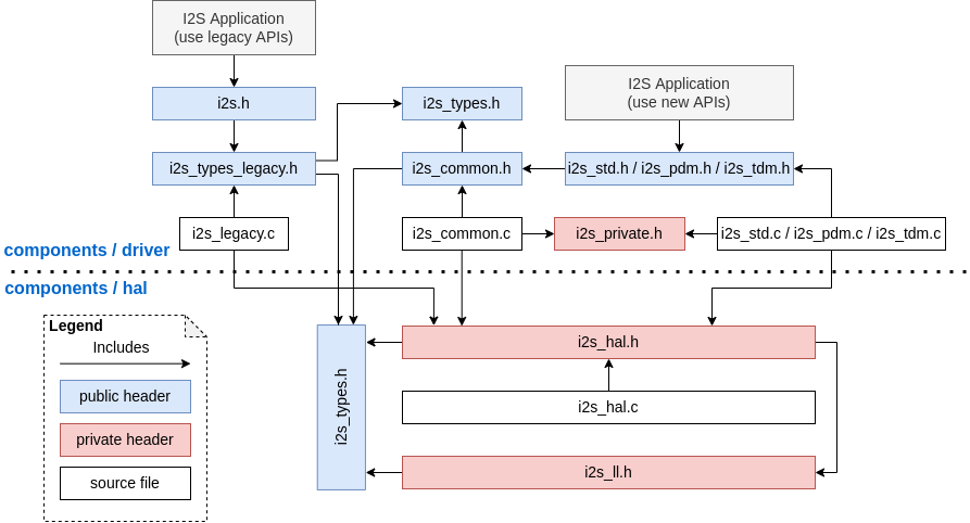
The I2S driver has been redesigned (see I2S Driver), which aims to rectify the shortcomings of the driver that were exposed when supporting all the new features of ESP32-C3 & ESP32-S3. The new driver's APIs are available by including corresponding I2S mode's header files esp_driver_i2s/include/driver/i2s_std.h, esp_driver_i2s/include/driver/i2s_pdm.h, or esp_driver_i2s/include/driver/i2s_tdm.h.
Meanwhile, the old driver's APIs in driver/deprecated/driver/i2s.h are still supported for backward compatibility. But there will be warnings if users keep using the old APIs in their projects, these warnings can be suppressed by the Kconfig option CONFIG_I2S_SUPPRESS_DEPRECATE_WARN.
Here is the general overview of the current I2S files:
Breaking changes in Concepts
Independent TX/RX channels
The minimum control unit in new I2S driver are now individual TX/RX channels instead of an entire I2S controller (that consists of multiple channels).
The TX and RX channels of the same I2S controller can be controlled separately, meaning that they are configured such that they can be started or stopped separately.
The
i2s_chan_handle_thandle type is used to uniquely identify I2S channels. All the APIs require the channel handle and users need to maintain the channel handles by themselves.On the ESP32-C3 and ESP32-S3, TX and RX channels in the same controller can be configured to different clocks or modes.
However, on the ESP32 and ESP32-S2, the TX and RX channels of the same controller still share some hardware resources. Thus, configurations may cause one channel to affect another channel in the same controller.
The channels can be registered to an available I2S controller automatically by setting
i2s_port_t::I2S_NUM_AUTOas I2S port ID which causes the driver to search for the available TX/RX channels. However, the driver also supports registering channels to a specific port.In order to distinguish between TX/RX channels and sound channels, the term "channel" in the context of the I2S driver only refers to TX/RX channels. Meanwhile, sound channels are referred to as "slots".
I2S Mode Categorization
I2S communication modes are categorized into the following three modes. Note that:
Standard mode: Standard mode always has two slots, it can support Philips, MSB, and PCM (short frame sync) formats. Please refer to esp_driver_i2s/include/driver/i2s_std.h for more details.
PDM mode: PDM mode only supports two slots with 16-bit data width, but the configurations of PDM TX and PDM RX are slightly different. For PDM TX, the sample rate can be set by
i2s_pdm_tx_clk_config_t::sample_rate, and its clock frequency depends on the up-sampling configuration. For PDM RX, the sample rate can be set byi2s_pdm_rx_clk_config_t::sample_rate, and its clock frequency depends on the down-sampling configuration. Please refer to esp_driver_i2s/include/driver/i2s_pdm.h for details.TDM mode: TDM mode can support up to 16 slots. It can work in Philips, MSB, PCM (short frame sync), and PCM (long frame sync) formats. Please refer to esp_driver_i2s/include/driver/i2s_tdm.h for details.
When allocating a new channel in a specific mode, users should initialize that channel by its corresponding function. It is strongly recommended to use the helper macros to generate the default configurations in case the default values are changed in the future.
Independent Slot and Clock Configuration
The slot configurations and clock configurations can be configured separately.
Call
i2s_channel_init_std_mode(),i2s_channel_init_pdm_rx_mode(),i2s_channel_init_pdm_tx_mode(), ori2s_channel_init_tdm_mode()to initialize the slot/clock/gpio_pin configurations.Calling
i2s_channel_reconfig_std_slot(),i2s_channel_reconfig_pdm_rx_slot(),i2s_channel_reconfig_pdm_tx_slot(), ori2s_channel_reconfig_tdm_slot()can change the slot configurations after initialization.Calling
i2s_channel_reconfig_std_clock(),i2s_channel_reconfig_pdm_rx_clock(),i2s_channel_reconfig_pdm_tx_clock(), ori2s_channel_reconfig_tdm_clock()can change the clock configurations after initialization.Calling
i2s_channel_reconfig_std_gpio(),i2s_channel_reconfig_pdm_rx_gpio(),i2s_channel_reconfig_pdm_tx_gpio(), ori2s_channel_reconfig_tdm_gpio()can change the GPIO configurations after initialization.
Misc
States and state-machine are adopted in the new I2S driver to avoid APIs called in wrong state.
ADC and DAC modes are removed. They are only supported in their own drivers and the legacy I2S driver.
Breaking Changes in Usage
To use the new I2S driver, please follow these steps:
Call
i2s_new_channel()to acquire channel handles. We should specify the work role and I2S port in this step. Besides, the TX or RX channel handle will be generated by the driver. Inputting both two TX and RX channel handles is not necessary but at least one handle is needed. In the case of inputting both two handles, the driver will work at the duplex mode. Both TX and RX channels will be available on a same port, and they will share the MCLK, BCLK and WS signal. But if only one of the TX or RX channel handle is inputted, this channel will only work in the simplex mode.Call
i2s_channel_init_std_mode(),i2s_channel_init_pdm_rx_mode(),i2s_channel_init_pdm_tx_mode()ori2s_channel_init_tdm_mode()to initialize the channel to the specified mode. Corresponding slot, clock and GPIO configurations are needed in this step.(Optional) Call
i2s_channel_register_event_callback()to register the ISR event callback functions. I2S events now can be received by the callback function synchronously, instead of from the event queue asynchronously.Call
i2s_channel_enable()to start the hardware of I2S channel. In the new driver, I2S does not start automatically after installed, and users are supposed to know clearly whether the channel has started or not.Read or write data by
i2s_channel_read()ori2s_channel_write(). Certainly, only the RX channel handle is suppoesd to be inputted ini2s_channel_read()and the TX channel handle ini2s_channel_write().(Optional) The slot, clock and GPIO configurations can be changed by corresponding 'reconfig' functions, but
i2s_channel_disable()must be called before updating the configurations.Call
i2s_channel_disable()to stop the hardware of I2S channel.Call
i2s_del_channel()to delete and release the resources of the channel if it is not needed any more, but the channel must be disabled before deleting it.
TWAI Driver
The deprecated CAN peripheral driver is removed. Please use TWAI driver instead (i.e., include driver/twai.h in your application).
Register Access Macros
Previously, all register access macros could be used as expressions, so the following was allowed:
uint32_t val = REG_SET_BITS(reg, bits, mask);
In ESP-IDF v5.0, register access macros which write or read-modify-write the register can no longer be used as expressions, and can only be used as statements. This applies to the following macros: REG_WRITE, REG_SET_BIT, REG_CLR_BIT, REG_SET_BITS, REG_SET_FIELD, WRITE_PERI_REG, CLEAR_PERI_REG_MASK, SET_PERI_REG_MASK, SET_PERI_REG_BITS.
To store the value which would have been written into the register, split the operation as follows:
uint32_t new_val = REG_READ(reg) | mask;
REG_WRITE(reg, new_val);
To get the value of the register after modification (which may be different from the value written), add an explicit read:
REG_SET_BITS(reg, bits, mask);
uint32_t new_val = REG_READ(reg);