SPI Slave driver
Overview
The ESP32 has four SPI peripheral devices, called SPI0, SPI1, HSPI and VSPI. SPI0 is entirely dedicated to the flash cache the ESP32 uses to map the SPI flash device it is connected to into memory. SPI1 is connected to the same hardware lines as SPI0 and is used to write to the flash chip. HSPI and VSPI are free to use, and with the spi_slave driver, these can be used as a SPI slave, driven from a connected SPI master.
The spi_slave driver
The spi_slave driver allows using the HSPI and/or VSPI peripheral as a full-duplex SPI slave. It can send/receive transactions within 64 bytes, or make use of DMA to send/receive transactions longer than that. However, there are some known issues when the DMA is enabled.
Terminology
The spi_slave driver uses the following terms:
- Host: The SPI peripheral inside the ESP32 initiating the SPI transmissions. One of HSPI or VSPI.
- Bus: The SPI bus, common to all SPI devices connected to a master. In general the bus consists of the
miso, mosi, sclk and optionally quadwp and quadhd signals. The SPI slaves are connected to these
signals in parallel. Each SPI slave is also connected to one CS signal.
- miso - Also known as q, this is the output of the serial stream from the ESP32 to the SPI master
- mosi - Also known as d, this is the output of the serial stream from the SPI master to the ESP32
- sclk - Clock signal. Each data bit is clocked out or in on the positive or negative edge of this signal
- cs - Chip Select. An active Chip Select delineates a single transaction to/from a slave.
- Transaction: One instance of CS going active, data transfer from and to a master happening, and CS going inactive again. Transactions are atomic, as in they will never be interrupted by another transaction.
SPI transactions
A full-duplex SPI transaction starts with the master pulling CS low. After this happens, the master starts sending out clock pulses on the CLK line: every clock pulse causes a data bit to be shifted from the master to the slave on the MOSI line and vice versa on the MISO line. At the end of the transaction, the master makes CS high again.
注解
The SPI slave peripheral relies on the control of software very much. The master shouldn’t start a transaction when the slave hasn’t prepared for it. Using one more GPIO as the handshake signal to sync is a good idea. For more details, see Transaction interval.
GPIO matrix and IOMUX
Most peripheral signals in ESP32 can connect directly to a specific GPIO, which is called its IOMUX pin. When a peripheral signal is routed to a pin other than its IOMUX pin, ESP32 uses the less direct GPIO matrix to make this connection.
If the driver is configured with all SPI signals set to their specific IOMUX pins (or left unconnected), it will bypass the GPIO matrix. If any SPI signal is configured to a pin other than its IOMUx pin, the driver will automatically route all the signals via the GPIO Matrix. The GPIO matrix samples all signals at 80MHz and sends them between the GPIO and the peripheral.
When the GPIO matrix is used, setup time of MISO is more easily violated, since the output delay of MISO signal is increased.
注解
More details about influence of output delay on the maximum clock frequency, see Timing considerations below.
IOMUX pins for SPI controllers are as below:
| Pin Name | HSPI | VSPI |
|---|---|---|
| GPIO Number | ||
| CS0* | 15 | 5 |
| SCLK | 14 | 18 |
| MISO | 12 | 19 |
| MOSI | 13 | 23 |
| QUADWP | 2 | 22 |
| QUADHD | 4 | 21 |
note * Only the first device attaching to the bus can use CS0 pin.
Using the spi_slave driver
- Initialize a SPI peripheral as a slave by calling
spi_slave_initialize. Make sure to set the correct IO pins in thebus_configstruct. Take care to set signals that are not needed to -1. A DMA channel (either 1 or 2) must be given if transactions will be larger than 32 bytes, if not the dma_chan parameter may be 0. - To set up a transaction, fill one or more spi_transaction_t structure with any transaction
parameters you need. Either queue all transactions by calling
spi_slave_queue_trans, later quering the result usingspi_slave_get_trans_result, or handle all requests synchroneously by feeding them intospi_slave_transmit. The latter two functions will block until the master has initiated and finished a transaction, causing the queued data to be sent and received. - Optional: to unload the SPI slave driver, call
spi_slave_free.
Transaction data and master/slave length mismatches
Normally, data to be transferred to or from a device will be read from or written to a chunk of memory
indicated by the rx_buffer and tx_buffer members of the transaction structure. The SPI driver
may decide to use DMA for transfers, so these buffers should be allocated in DMA-capable memory using
pvPortMallocCaps(size, MALLOC_CAP_DMA).
The amount of data written to the buffers is limited by the length member of the transaction structure:
the driver will never read/write more data than indicated there. The length cannot define the actual
length of the SPI transaction; this is determined by the master as it drives the clock and CS lines. The actual length
transferred can be read from the trans_len member of the spi_slave_transaction_t structure after transaction.
In case the length of the transmission is larger than the buffer length, only the start of the transmission
will be sent and received, and the trans_len is set to length instead of the actual length. It’s recommended to
set length longer than the maximum length expected if the trans_len is required. In case the transmission
length is shorter than the buffer length, only data up to the length of the buffer will be exchanged.
Warning: Due to a design peculiarity in the ESP32, if the amount of bytes sent by the master or the length of the transmission queues in the slave driver, in bytes, is not both larger than eight and dividable by four, the SPI hardware can fail to write the last one to seven bytes to the receive buffer.
Speed and Timing considerations
Transaction interval
The SPI slave is designed as s general purpose device controlled by the CPU. Different from dedicated devices, CPU-based SPI slave doesn’t have too much pre-defined registers. All transactions should be triggered by the CPU, which means the response speed would not be real-time, and there’ll always be noticeable intervals between transfers.
During the transaction intervals, the device is not prepared for
transactions, the response is not meaningful at all. It is suggested to use
spi_slave_queue_trans() with spi_slave_get_trans_result()
to shorten the interval to half the case when using
spi_slave_transmit().
The master should always wait for the slave to be ready to start new transactions. Suggested way is to use a gpio by the slave to indicate whether it’s ready. The example is in peripherals/spi_slave.
SCLK frequency requirement
The spi slave is designed to work under 10MHz or lower. The clock and data cannot be recognized or received correctly if the clock is too fast or doesn’t have a 50% duty cycle.
Moreover, there are more requirements if the data meets the timing requirement:
- Read (MOSI):
Given that the MOSI is valid right at the launch edge, the slave can read data correctly. Luckily, it’s usually the case for most masters.
- Write (MISO):
To meet the requirement that MISO is stable before the next latch edge of SPI clock, the output delay of MISO signal should be shorter than half a clock. The output delay and frequency limitation (given that the clock is balanced) of different cases are as below :
Output delay of MISO (ns) Freq. limit (MHZ) IOMUX 43.75 <11.4 GPIO matrix 68.75 <7.2 - Note:
- Random error will happen if the frequency exactly equals the limitation
- The clock uncertainty between master and slave (12.5ns) is included.
- The output delay is measured under ideal case (free of load). When the loading of MISO pin is too heavy, the output delay will be longer, and the maximum allowed frequency will be lower.
There is an exceptions: The frequency is allowed to be higher if the master has more toleration for the MISO setup time, e.g. latch data at the next edge than expected, or configurable latching time.
Restrictions and Known issues
If the DMA is enabled, the rx buffer should be WORD aligned, i.e. Start from the boundary of 32-bit and have length of multiples of 4 bytes. Or the DMA may write incorrectly or out of the boundary.The driver will check for this.
Also, master should write lengths which are a multiple of 4 bytes. Data longer than that will be discarded.
Furthurmore, the DMA requires a spi mode 1/3 timing. When using spi mode 0/2, the MISO signal has to output half a clock earlier to meet the timing. The new timing is as below:
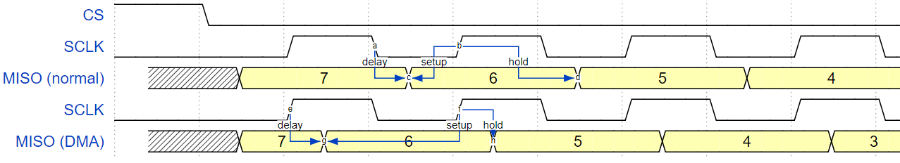
The hold time after the latch edge is 68.75ns (when GPIO matrix is bypassed), no longer half a SPI clock. The master should sample immediately at the latch edge, or communicate in mode 1/3. Or just initial the spi slave without DMA.
Application Example
Slave/master communication: peripherals/spi_slave.
API Reference
Header File
Functions
-
esp_err_t
spi_slave_initialize(spi_host_device_t host, const spi_bus_config_t *bus_config, const spi_slave_interface_config_t *slave_config, int dma_chan)¶ Initialize a SPI bus as a slave interface.
- Warning
- For now, only supports HSPI and VSPI.
- Warning
- If a DMA channel is selected, any transmit and receive buffer used should be allocated in DMA-capable memory.
- Warning
- The ISR of SPI is always executed on the core which calls this function. Never starve the ISR on this core or the SPI transactions will not be handled.
- Return
- ESP_ERR_INVALID_ARG if configuration is invalid
- ESP_ERR_INVALID_STATE if host already is in use
- ESP_ERR_NO_MEM if out of memory
- ESP_OK on success
- Parameters
host: SPI peripheral to use as a SPI slave interfacebus_config: Pointer to a spi_bus_config_t struct specifying how the host should be initializedslave_config: Pointer to a spi_slave_interface_config_t struct specifying the details for the slave interfacedma_chan: Either 1 or 2. A SPI bus used by this driver must have a DMA channel associated with it. The SPI hardware has two DMA channels to share. This parameter indicates which one to use.
-
esp_err_t
spi_slave_free(spi_host_device_t host)¶ Free a SPI bus claimed as a SPI slave interface.
- Return
- ESP_ERR_INVALID_ARG if parameter is invalid
- ESP_ERR_INVALID_STATE if not all devices on the bus are freed
- ESP_OK on success
- Parameters
host: SPI peripheral to free
-
esp_err_t
spi_slave_queue_trans(spi_host_device_t host, const spi_slave_transaction_t *trans_desc, TickType_t ticks_to_wait)¶ Queue a SPI transaction for execution.
Queues a SPI transaction to be executed by this slave device. (The transaction queue size was specified when the slave device was initialised via spi_slave_initialize.) This function may block if the queue is full (depending on the ticks_to_wait parameter). No SPI operation is directly initiated by this function, the next queued transaction will happen when the master initiates a SPI transaction by pulling down CS and sending out clock signals.
This function hands over ownership of the buffers in
trans_descto the SPI slave driver; the application is not to access this memory untilspi_slave_queue_transis called to hand ownership back to the application.- Return
- ESP_ERR_INVALID_ARG if parameter is invalid
- ESP_OK on success
- Parameters
host: SPI peripheral that is acting as a slavetrans_desc: Description of transaction to execute. Not const because we may want to write status back into the transaction description.ticks_to_wait: Ticks to wait until there’s room in the queue; use portMAX_DELAY to never time out.
-
esp_err_t
spi_slave_get_trans_result(spi_host_device_t host, spi_slave_transaction_t **trans_desc, TickType_t ticks_to_wait)¶ Get the result of a SPI transaction queued earlier.
This routine will wait until a transaction to the given device (queued earlier with spi_slave_queue_trans) has succesfully completed. It will then return the description of the completed transaction so software can inspect the result and e.g. free the memory or re-use the buffers.
It is mandatory to eventually use this function for any transaction queued by
spi_slave_queue_trans.- Return
- ESP_ERR_INVALID_ARG if parameter is invalid
- ESP_OK on success
- Parameters
host: SPI peripheral to that is acting as a slavetrans_desc: Pointer to variable able to contain a pointer to the description of the transaction that is executedticks_to_wait: Ticks to wait until there’s a returned item; use portMAX_DELAY to never time out.
-
esp_err_t
spi_slave_transmit(spi_host_device_t host, spi_slave_transaction_t *trans_desc, TickType_t ticks_to_wait)¶ Do a SPI transaction.
Essentially does the same as spi_slave_queue_trans followed by spi_slave_get_trans_result. Do not use this when there is still a transaction queued that hasn’t been finalized using spi_slave_get_trans_result.
- Return
- ESP_ERR_INVALID_ARG if parameter is invalid
- ESP_OK on success
- Parameters
host: SPI peripheral to that is acting as a slavetrans_desc: Pointer to variable able to contain a pointer to the description of the transaction that is executed. Not const because we may want to write status back into the transaction description.ticks_to_wait: Ticks to wait until there’s a returned item; use portMAX_DELAY to never time out.
Structures
-
struct
spi_slave_interface_config_t¶ This is a configuration for a SPI host acting as a slave device.
Public Members
-
int
spics_io_num¶ CS GPIO pin for this device.
-
uint32_t
flags¶ Bitwise OR of SPI_SLAVE_* flags.
-
int
queue_size¶ Transaction queue size. This sets how many transactions can be ‘in the air’ (queued using spi_slave_queue_trans but not yet finished using spi_slave_get_trans_result) at the same time.
-
uint8_t
mode¶ SPI mode (0-3)
-
slave_transaction_cb_t
post_setup_cb¶ Callback called after the SPI registers are loaded with new data.
This callback is called within interrupt context should be in IRAM for best performance, see “Transferring Speed” section in the SPI Master documentation for full details. If not, the callback may crash during flash operation when the driver is initialized with ESP_INTR_FLAG_IRAM.
-
slave_transaction_cb_t
post_trans_cb¶ Callback called after a transaction is done.
This callback is called within interrupt context should be in IRAM for best performance, see “Transferring Speed” section in the SPI Master documentation for full details. If not, the callback may crash during flash operation when the driver is initialized with ESP_INTR_FLAG_IRAM.
-
int
-
struct
spi_slave_transaction_t¶ This structure describes one SPI transaction
Public Members
-
size_t
length¶ Total data length, in bits.
-
size_t
trans_len¶ Transaction data length, in bits.
-
const void *
tx_buffer¶ Pointer to transmit buffer, or NULL for no MOSI phase.
-
void *
rx_buffer¶ Pointer to receive buffer, or NULL for no MISO phase. When the DMA is anabled, must start at WORD boundary (
rx_buffer%4==0), and has length of a multiple of 4 bytes.
-
void *
user¶ User-defined variable. Can be used to store eg transaction ID.
-
size_t
Macros
-
SPI_SLAVE_TXBIT_LSBFIRST¶ Transmit command/address/data LSB first instead of the default MSB first.
-
SPI_SLAVE_RXBIT_LSBFIRST¶ Receive data LSB first instead of the default MSB first.
-
SPI_SLAVE_BIT_LSBFIRST¶ Transmit and receive LSB first.
Type Definitions
-
typedef struct spi_slave_transaction_t
spi_slave_transaction_t
-
typedef void (*
slave_transaction_cb_t)(spi_slave_transaction_t *trans)