ESP-Modbus
Overview
The Modbus serial communication protocol is de facto standard protocol widely used to connect industrial electronic devices. Modbus allows communication among many devices connected to the same network, for example, a system that measures temperature and humidity and communicates the results to a computer. The Modbus protocol uses several types of data: Holding Registers, Input Registers, Coils (single bit output), Discrete Inputs. Versions of the Modbus protocol exist for serial port and for Ethernet and other protocols that support the Internet protocol suite. There are many variants of Modbus protocols, some of them are:
Modbus RTU— This is used in serial communication and makes use of a compact, binary representation of the data for protocol communication. The RTU format follows the commands/data with a cyclic redundancy check checksum as an error check mechanism to ensure the reliability of data. Modbus RTU is the most common implementation available for Modbus. A Modbus RTU message must be transmitted continuously without inter-character hesitations. Modbus messages are framed (separated) by idle (silent) periods. The RS-485 interface communication is usually used for this type.
Modbus ASCII— This is used in serial communication and makes use of ASCII characters for protocol communication. The ASCII format uses a longitudinal redundancy check checksum. Modbus ASCII messages are framed by leading colon (“:”) and trailing newline (CR/LF).
Modbus TCP/IP or Modbus TCP— This is a Modbus variant used for communications over TCP/IP networks, connecting over port 502. It does not require a checksum calculation, as lower layers already provide checksum protection.
Note
This documentation (and included code snippets) requires some familiarity with the Modbus protocol. Refer to the Modbus Organization’s with protocol specifications for specifics Protocol References.
Modbus Supported Communication Options
The Modbus library supports the standard communication options as per Modbus specification stated below.
Modbus option |
Description of the option |
|---|---|
RTU communication |
|
ASCII communication |
|
TCP communication |
|
Some vendors may use subset of communication options. In this case the detailed information is clarified in the device manual and it is possible to override the standard communication options for support of such devices. Please refer to Slave Communication Options, Master Communication Options for more information.
Messaging Model And Data Mapping
Modbus is an application protocol that defines rules for messaging structure and data organization that are independent of the data transmission medium. Traditional serial Modbus is a register-based protocol that defines message transactions that occur between master(s) and slave devices (multiple masters are allowed on using Modbus TCP/IP). The slave devices listen for communication from the master and simply respond as instructed. The master(s) always controls communication and may communicate directly to one slave, or all connected slaves, but the slaves cannot communicate directly with each other.
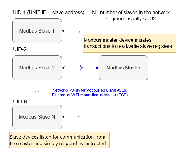
Modbus segment diagram
Note
It is assumed that the number of slaves and their register maps are known by the Modbus master before the start of stack.
The register map of each slave device is usually part of its device manual. A Slave device usually permits configuration of its short slave address and communication options that are used within the device’s network segment.
The Modbus protocol allows devices to map data to four types of registers (Holding, Input, Discrete, Coil). The figure below illustrates an example mapping of a device’s data to the four types of registers.
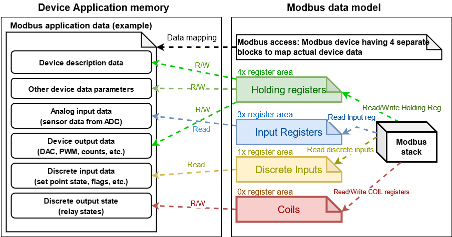
Modbus data mapping
Mapping Of Complex Data Types
As per section 4.2 of Modbus specification, “MODBUS uses a big-Endian representation for addresses and data items. This means that when a numerical quantity larger than a single byte is transmitted, the most significant byte is sent first”. The biggest official structure defined by the Modbus specification is a 16-bit word register, which is 2 bytes. However, vendors sometimes group two or even four 16-bit registers together to be interpretted as 32-bit or 64-bit values, respectively. It is also possible when the Modbus vendors group many registers together for serial numbers, text strings, time/date, etc. Regardless of how the vendor intends the data to be interpreted, the Modbus protocol itself simply transfers 16-bit word registers. These values grouped from registers may use either little-endian or big-endian register order.
Note
Each individual 16-bit register, is encoded in big-endian order (assuming the Modbus device abides by the Modbus specification). However, the 32-bit and 64-bit types naming conventions like ABCD or ABCDEFGH, does not take into account the network format byte order of frame. For example: the ABCD prefix for 32-bit values means the common Modbus mapping format and corresponds to the CDAB on network format (order in the frame).
Common Data Types Supported By Modbus Vendors
Type |
Range |
Format description |
|---|---|---|
U8, I8 - Unsigned/Signed 8-bit type |
(0 .. 255)/(-128 .. 127) |
Common unsigned 8-bit type that is stored usually in one Modbus register. The value can be stored in HI or LO byte of the register or packed with the next byte into one 16 - bit register. |
U16 - Unsigned integer 16-bit type |
0 - 65535 |
Stored in one 16-bit register. The values can be stored with AB or BA endianness. |
I16 - Signed integer 16-bit type |
-32768 to 32767 is allowed. |
Stored in one 16-bit register. The values can be stored with AB or BA forendiannessmat. |
I32 - Signed long integer 32-bit type |
-2147483648 to 2147483647 is allowed. |
Stored in two consecutive 16-bit register. The values can be stored with ABCD - DCBA endianness (see below). |
U32 - Unsigned long integer 32-bit type |
0 to 4294967295 is allowed. |
Stored in two consecutive 16-bit register. The values can be stored with ABCD - DCBA endianness. |
U64 Unsigned Long long integers (Unsigned integer 64) |
0 to 18446744073709551615 is allowed. |
Stored in four consecutive 16-bit register. The values can be stored with ABCDEFGH - BADCFEHG endianness. |
I64 Signed Long long integers (Signed integer 64) |
-9223372036854775808 to 9223372036854775807 is allowed. |
Stored in four consecutive 16-bit register. The values can be stored with ABCDEFGH - BADCFEHG endianness. |
Floating point single precision 32-bit |
1.17549435E-38 to 3.40282347E+38 is allowed. |
Stored in two consecutive 16-bit register per IEEE754. The values can be stored with ABCD - DCBA endianness. |
Floating point double precision 64-bit |
+/-5.0E-324 to +/-1.7E+308 is allowed. |
Stored in four consecutive 16-bit register per IEEE754. The values can be stored with ABCDEFGH - BADCFEHG endianness. |
As showed in the table above the float and double types do not fit to the 16-bit register and reguire several consecutive registers be used to store the value. However, different manufacturers store the consecutive bytes in different order (not standardized). For example: The DCBA prefix means inversed Modbus format (BADC order on network format).
Postfix |
Format description |
|---|---|
ABCD |
Big endian, high order byte first |
CDAB |
Big endian, reversed register order (Little endian with byte swap) |
BADC |
Little endian, reversed register order (Big endian with byte swap) |
DCBA |
Little endian (Low order byte first) |
The extended data types are used to define all possible combinations of groupped values are represented below and correspond to param_type field of the data dictionary as described in the table below:
Type |
Format type description (common format) |
Format type (network format) |
|---|---|---|
compatibility type corresponds to |
Unsigned integer 8 bit type |
|
Unsigned integer 16 bit type, corresponds to |
Little endian byte swap |
|
Default unsigned integer 32 bit type, corresponds to |
Little endian byte swap |
|
Default unsigned integer 32 bit type, corresponds to |
Little endian byte swap |
|
Default ASCII string format |
Packed ASCII string data |
|
Binary data type |
Default type for binary packed data |
|
I8 signed integer in low byte of register, high byte is zero |
I8 signed integer LO |
|
I8 signed integer in high byte of register, low byte is zero |
I8 signed integer HI |
|
U8 unsigned integer written to low byte of register, high byte is zero |
U8 unsigned integer LO |
|
U8 unsigned integer written to hi byte of register, low byte is zero |
U8 unsigned integer HI |
|
I16 signed integer, big endian |
Big endian |
|
I16 signed integer, little endian |
Little endian |
|
U16 unsigned integer, big endian |
Big endian |
|
U16 unsigned integer, little endian |
Little endian |
|
I32 ABCD signed integer, big endian |
Little endian byte swap |
|
I32 CDAB signed integer, big endian, reversed register order |
Big endian |
|
I32 BADC signed integer, little endian, reversed register order |
Little endian |
|
I32 DCBA signed integer, little endian |
Big endian byte swap |
|
U32 ABCD unsigned integer, big endian |
Little endian byte swap |
|
U32 CDAB unsigned integer, big endian, reversed register order |
Big endian |
|
U32 BADC unsigned integer, little endian, reversed register order |
Little endian |
|
U32 DCBA unsigned integer, little endian |
Big endian byte swap |
|
Float ABCD floating point, big endian |
Little endian byte swap |
|
Float CDAB floating point, big endian, reversed register order |
Big endian |
|
Float BADC floating point, little endian, reversed register order |
Little endian |
|
Float DCBA floating point, little endian |
Big endian byte swap |
|
I64, ABCDEFGH signed integer, big endian |
Little endian byte swap |
|
I64, HGFEDCBA signed integer, little endian |
Big endian byte swap |
|
I64, GHEFCDAB signed integer, big endian, reversed register order |
Big endian |
|
I64, BADCFEHG signed integer, little endian, reversed register order |
Little endian |
|
U64, ABCDEFGH unsigned integer, big endian |
Little endian byte swap |
|
U64, HGFEDCBA unsigned integer, little endian |
Big endian byte swap |
|
U64, GHEFCDAB unsigned integer, big endian, reversed register order |
Big endian |
|
U64, BADCFEHG unsigned integer, little endian, reversed register order |
Little endian |
|
Double ABCDEFGH floating point, big endian |
Little endian byte swap |
|
Double HGFEDCBA floating point, little endian |
Big endian byte swap |
|
Double GHEFCDAB floating point, big endian, reversed register order |
Big endian |
|
Double BADCFEHG floating point, little endian, reversed register order |
Little endian |
Note
The support for the extended data types should be enabled using the option CONFIG_FMB_EXT_TYPE_SUPPORT in kconfig menu.
The below diagrams show how the extended data types appear on network layer.
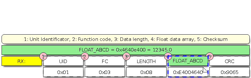
Modbus master response with ABCD frame
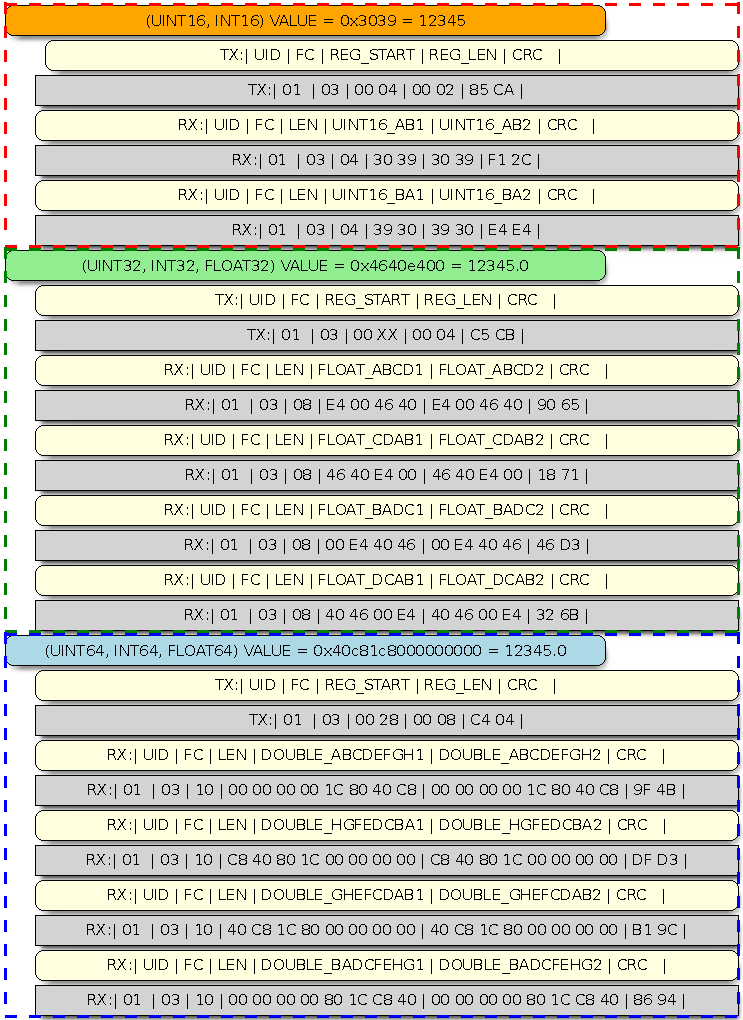
Modbus frame packaging examples (16-bit, 32-bit, 64-bit data)
The approach showed above can be used to pack the data into MBAP frames used by Modbus TCP as well as for other types with similar size.
The following sections give an overview of how to use the ESP_Modbus component found under components/freemodbus. The sections cover initialization of a Modbus port, and the setup a master or slave device accordingly: