Note
The version of ESP-IDF corresponding to this document is v5.5.0
LEDC Basic Example
Note
This document is automatically translated using AI. Please excuse any detailed errors. The official English version is still in progress.
Example Description
LEDC is a dedicated peripheral used to generate multi-channel Pulse Width Modulation (PWM) signals, which can be used to adjust LED brightness or control motor speed, etc. Through LEDC, channels, timers, and duty cycles can be flexibly configured to achieve precise PWM signal output.
This example shows how to initialize and configure the LEDC module, and demonstrates how to adjust the duty cycle during the PWM signal output process.
Running Method
The complete code of the example can be found at LEDC Basic Example. For configuration instructions, pin connections, build and burn processes before running, please refer to the README.md file in the example directory.
For custom configuration items and default values, please refer to the Macro Definition Description section.
Header File Description
The header files used in this example cover system tools and LEDC driver modules, providing support for input/output, error handling, and configuration and control of LEDC peripherals during task execution.
The header files are categorized by function as follows:
System Tools: Provide input/output and error code management functions.
#include <stdio.h>
#include <"esp_err.h">
LEDC Driver: Provides LEDC configuration and PWM waveform generation functions.
#include "driver/ledc.h"
Macro Definition Description
The macro definitions in this example are mainly used to configure the LEDC peripherals of the ESP32 chip, covering timers, channels, GPIO pins, modes, resolutions, duty cycles, and frequencies.
The macro definitions are categorized by function as follows:
Timer Configuration
Defines the timer used by LEDC, provides a clock basis for channel output, and determines the resolution and frequency of the PWM signal. The number of timers varies with the chip model, and most ESP32 chips provide 4 timers. The functions of each timer are the same, and the differences are only in the occupancy situation and whether the required configuration can be met. Timer 0 is selected in this example.
#define LEDC_TIMER LEDC_TIMER_0
Channel, Mode, and GPIO Configuration
Defines the output GPIO pin, which is set to GPIO5 in this example. The waveform of the output signal can be observed by connecting this pin to an oscilloscope.
#define LEDC_OUTPUT_IO (5)
Defines the channel used by LEDC, which is used to map the PWM signal generated by the timer to the actual GPIO pin. The number of channels varies with the chip model, and the functions of the channels are essentially the same. Each channel can independently set the duty cycle. Channel 0 is selected in this example.
#define LEDC_CHANNEL LEDC_CHANNEL_0
Defines the LEDC mode, which can choose high-speed mode or low-speed mode (some chips only support low-speed mode). In high-speed mode, parameter updates take effect immediately, while in low-speed mode, synchronous operation is required but power consumption is lower. For specific instructions and differences, please refer to Mode Description. Low-speed mode is used in this example.
#define LEDC_MODE LEDC_LOW_SPEED_MODE
LEDC Parameter Configuration:
Defines the resolution, which is used to determine the adjustment precision of the PWM duty cycle. The higher the resolution, the more delicate the duty cycle adjustment, but the maximum supported frequency will decrease. In this example, a 13-bit resolution is set. The corresponding duty cycle range is from 0 to 8191 (2^13 - 1).
#define LEDC_DUTY_RES LEDC_TIMER_13_BITNote
On some ESP32 chips, when the LEDC duty cycle resolution is configured to the maximum value supported by the hardware, it is impossible to output a 100% duty cycle. In practical applications, this limitation can be circumvented by reducing the resolution or setting the duty cycle to a value close to the maximum.
Define the duty cycle, which determines the “on/off time ratio” of the PWM signal, directly affecting the output power or brightness. In the example, it is defined as a 50% duty cycle, i.e., the signal on and off time is the same.
#define LEDC_DUTY (4096)Note
The percentage of the duty cycle can be converted into a specific value through the formula value = duty cycle percentage × 2^N, where N is the number of resolution bits. For example, when the duty cycle is 50%, the calculation result is 0.5 × 2^13 = 4096, so at 13-bit resolution, 4096 corresponds to a 50% duty cycle.
Define the frequency, which determines the speed of the PWM signal cycle, affecting the response of the peripheral. The higher the frequency, the lower the resolution limit. In the example, it is defined as a 50% duty cycle, i.e., the signal on and off time is the same.
#define LEDC_FREQUENCY (4000)Note
In practical applications, parameter selection usually follows the following ideas:
First determine the frequency range required by the application scenario;
Then choose a resolution that can meet the accuracy requirements
Finally, set the duty cycle according to actual needs.
Task Function Description
This example only includes the LEDC initialization function, which is used to configure the ESP32’s timer and channel for PWM signal output.
LEDC Initialization Function
example_ledc_init() is used to initialize the ESP32’s LEDC peripheral, completing the timer and channel configuration required for PWM signal output.
Timer Configuration: Used to determine the frequency and resolution of PWM.
Define the structure
ledc_timer_config_tfor configuring the timer.Call
ledc_timer_config()to apply the above timer configuration. For more features and parameter descriptions, please refer to LED PWM Controller API.
Channel Configuration: Used to bind GPIO and set the initial duty cycle.
Define the structure
ledc_channel_config_tfor configuring the channel.
The structure member
hpointis used to configure the starting point (phase control) of the signal high level, its value range is the same as the duty cycle resolution, and the output waveform phase offset can be achieved by adjustinghpoint.The structure member
sleep_modeis used to specify the behavior of this channel in Light Sleep mode, such as maintaining the output level or turning off the output.The structure member
flags.output_invertis used to set whether to invert the output waveform, with a value of 0 indicating normal output and 1 indicating inversion of high and low levels, mainly used to match the low-level valid logic of peripherals, maintain system signal compatibility, or optimize switch device characteristics, and can also reverse the direction of high and low levels when adjusting the brightness of devices such as LEDs.Invoke
ledc_channel_config()to apply the above channel configuration. For more features and parameter descriptions, refer to LED PWM Controller API.
After initialization, the LEDC peripheral can output PWM signals at the set frequency and duty cycle. The above initialization configuration steps are universal and applicable to all scenarios involving LEDC, and only need to adjust related parameters according to actual needs.
Main Function Description
This example demonstrates the initialization and PWM waveform output of the ESP32 LEDC peripheral, realizing the generation of PWM signals with a fixed duty cycle through a specified GPIO pin.
Call the task function
example_ledc_init()to initialize the LEDC peripheral, complete the timer and channel configuration, and prepare for PWM signal output.
Call
ledc_set_duty()to set the PWM duty cycle toLEDC_DUTY(macro definition, 50% duty cycle), determining the ratio of high level to low level. For more features and parameter descriptions, refer to LED PWM Controller API.Call
ledc_update_duty()to apply the set duty cycle to the specified LEDC channel, outputting the corresponding PWM waveform. For more features and parameter descriptions, refer to LED PWM Controller API.Note
When configuring the channel, the duty cycle is usually set to 0 to keep the output at a low level. This is to ensure that a valid PWM signal is not immediately output during the initialization process, avoiding sudden lighting of LEDs or accidental startup of motors.
After initialization, you can adjust the duty cycle according to actual needs by calling the API, thus safely controlling the output signal.
Program Phenomenon
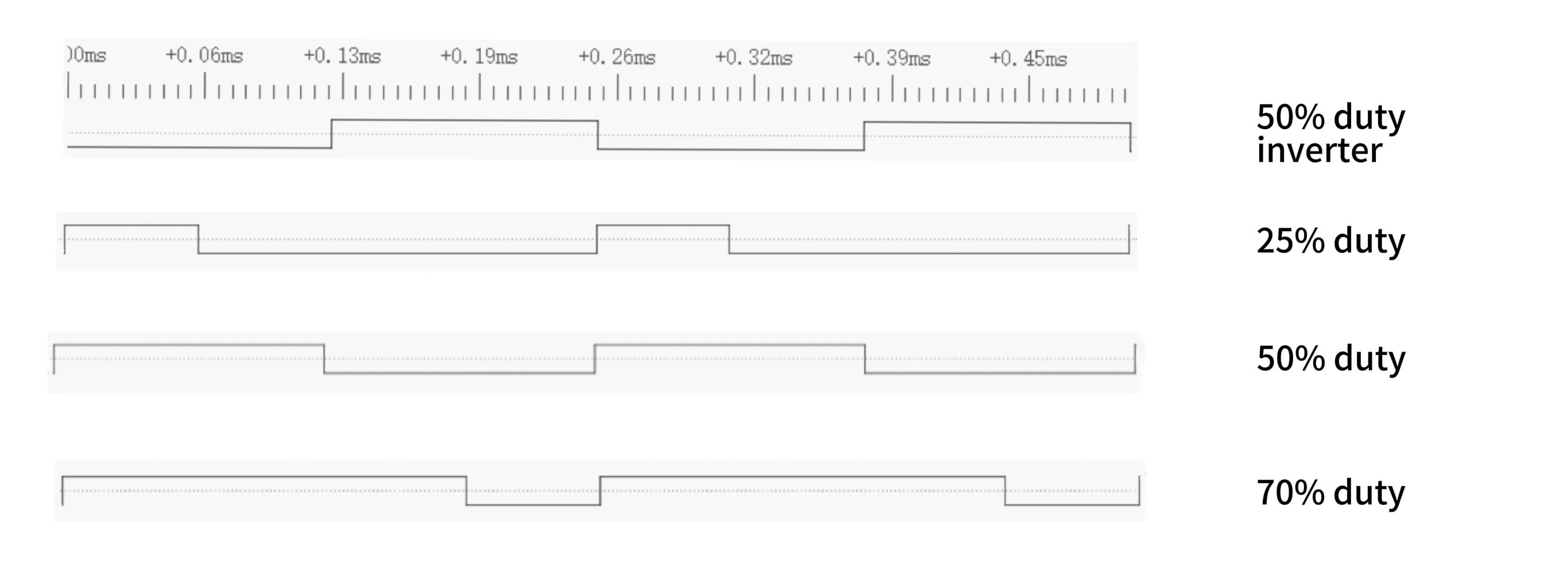
After the example runs, the GPIO pin outputs a PWM signal at a fixed frequency, and the waveform is a periodic square wave, which can be used for LED dimming, fan or other peripheral control.
In this example, the PWM signal duty cycle is set to 50%, and the high and low level durations are equal, each occupying half a cycle. To intuitively display the effect of the duty cycle, waveform examples of 25%, 75% duty cycle and 50% duty cycle reverse output are also shown. In the waveform, the duration of the high level changes with the duty cycle, and the reverse output swaps the high and low levels, but the cycle and duty cycle ratio remain unchanged. Through these waveform examples, you can intuitively observe the impact of different duty cycles and reverse outputs on the signal shape.