802.15.4 Non-Signaling Test directly controls the device to transmit specific signals without requiring a network connection. It evaluates key performance metrics such as transmit power, spectrum characteristics, and error rate, ensuring reliable communication quality in IoT applications.
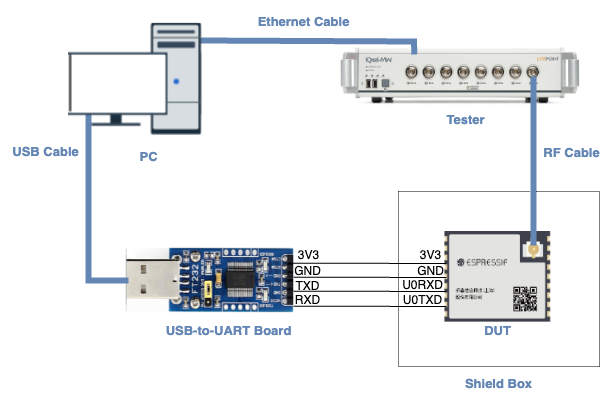
PC is connected to the USB-to-UART board via USB and to the tester via an Ethernet cable. The PC needs to have the EspRFTestTool toolkit, tester control software, and the driver for the USB-to-UART board installed.
Tester is used to test the RF performance of the DUT in different modes. Typically, it is the WT-328/IQXel tester.
USB-to-UART board is used to communicate between the PC and the DUT.
Device under test (DUT) refers to a product designed based on the ESP32-C6 chip or module. It is connected to the USB-to-UART board via UART and to the tester via an RF connection cable. The DUT is usually placed inside a shield box.
Shield Box is used to isolate external RF interference and ensure the stability of the test environment.
Note
The CHIP_EN pin of the DUT is pulled up by default. If it is not pulled up in the product design, you need to manually connect the CHIP_EN to the 3V3 pin.
Some serial communication boards have already swapped RXD and TXD internally, so there is no need to reverse the connection. Adjust the wiring according to the actual situation.
ESP32-C6 has a power-on self-calibration feature. The RF connection cable must be connected to the tester before the DUT is powered on for testing.
For modules without an onboard PCB antenna, the RF connection cable can be directly soldered to the antenna feed point of the module (as shown in the schematic diagram above).
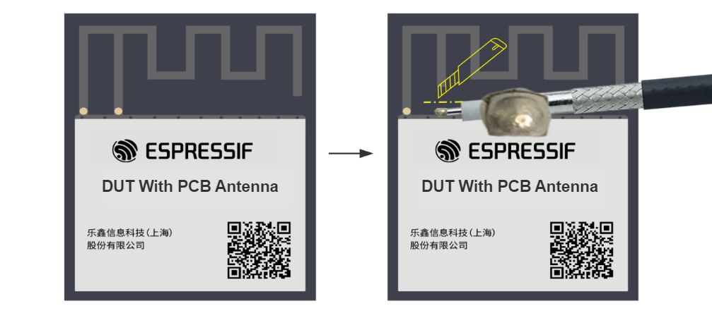
For modules with an onboard PCB antenna, cut the trace that connects to the PCB antenna feed point and solder the RF connection cable. The RF cable’s shielding metal layer must be thoroughly soldered before connecting to the module’s GND. The GND soldering point can be either the shield cover or the exposed GND layer on the PCB (after removing the green solder mask). Besides, it should be as close to the feed point as possible.
Soldering RF Connection Cable to Module with Onboard PCB Antenna
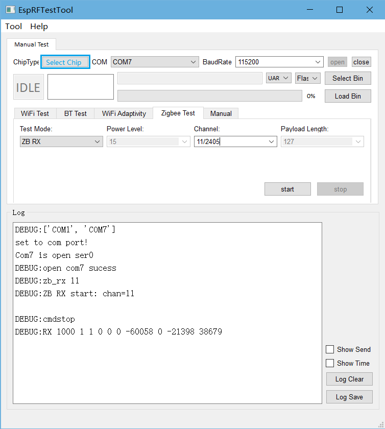
Test Mode: Set to ZB RX for Zigbee RX performance test.
Channel: Set the Zigbee test channel.
After clicking start, use the tester to send packets on the test channel. Click stop after completion. The packet RX information is displayed in the log window, similar to the following:
RX100011000-600580-2139838679
Among them:
The first parameter Res[0] returns the string “RX”.
The second parameter Res[1] (decimal) indicates the number of packets received at the corresponding rate in this test. In this test, Res[1] is 1000.
The fourth last parameter, Res[7] (in decimal), represents the total RSSI of the packets received at the corresponding rate in this test. In this test, Res[7] is -60058.
Based on the above parameters, you can calculate:
Packet loss rate PER = [1-(Res[1]/Sent_Packet_Numbers)]*100%<=1%