ESP32-Sense-Kit
Overview
The ESP32 touch sensor development kit, ESP32-Sense-Kit, is used for evaluating and developing ESP32 touch sensor system. ESP32-Sense-Kit consists of one motherboard and multiple daughterboards. The motherboard contains a display unit, a main control unit and a debug unit. The daughterboards have touch electrodes in different combinations or shapes, such as linear slider, wheel slider, matrix buttons and spring buttons, depending on the application scenarios. Users can design and add their own daughterboards for special usage cases.
The following image shows the whole ESP32-Sense-Kit.

ESP32-Sense-Kit
Preparation
Install overlay
If plastic is used for the overlay, the recommended thickness is 3 mm or less. Because air reduces touch sensitivity, any air gaps between the daughterboard and overlay must be eliminated. You can use double-sided adhesive tape to fill in the air gap. For the daughterboard with metal springs, 7 mm stud bolts should be used to install the overlay.

Install Overlay
Install daughterboard
Use a connector to connect motherboard with daughterboard. You can use four 7 mm plastic stud bolts to have the daughterboard steadily parallel to the motherboard, as shown in the image below:

Install Daughterboard
Set ESP-Prog debugger
ESP-Prog is used as the program download tool and power supply. ESP-Prog has two sets of jumpers: IO0 jumper and power supply jumper. Choose 5 V power supply for the latter. IO0 can be used both for selecting boot mode (download mode or working mode) and as a touch pin. As a result, it should be disconnected if used as a touch pin in working mode. The image below shows the settings for ESP-Prog.

Set ESP-Prog Debuggers
Connect ESP-Prog with motherboard
The ESP-Prog has a Jtag interface and a Program interface. Connect ESP-Prog and the motherboard through the Program interface.

Connect ESP-Prog with Motherboard
Download programs
Run
make menuconfigto configure the config settings for ESP32-Sense Project, as the screenshot below shows. Runmake flashto download programs into the development board.


Download Programs
Replace daughterboard
ESP32 will detect the divided voltage of the voltage divider on the daughterboard when it is powered on to identify different daughterboards. Re-power on the development board after replacing the daughterboard.
Hardware Resources
Motherboard
Function Block Diagram
The image below shows the function block diagram of the motherboard.

Function Block Diagram
Motherboard Components
The display unit includes three segment displays and an RGB circuit. The debug unit includes the ESP-Prog debugger interface. The main control unit includes the ESP32 module. The mini USB is the power supply.

Motherboard Components
Power Management System
The mini USB and ESP-Prog can both be the power supply for ESP32-Sense Kit. They do not interfere with each other thanks to the protection diode. The mini USB can only serve as the power supply, while ESP-Prog also supports automatic firmware downloading. The figure below shows the schematics of the power management system.

Power Management System
Display Unit
The display unit on the motherboard can intuitively feedback touch event. The three 7-segment displays show the location of the pad that is being touched and the duration of a touch event. The segment displays are driven by CH455G chip, and controlled through I2C interface. The RGB LED reflects the colors when a touch event occurs. When a finger moves on the slider, the RGB LED will show the change of colors.
The figure below shows the schematics of the display unit:


Display Unit
Daughterboard
Divided resistance
The touch electrodes are arranged in different combinations depending on the application scenario. Each daughterboard has a voltage divider that has a unique value. The program running on motherboard reads the divider value through ADC and thus each daughterboard can be identified. The voltage divider is shown below:

Voltage Divider
The divided resistance on the motherboard is 10 KΩ. The table below lists the divided resistance on each daughterboard.
Daughterboard |
Divided resistance (Kohm) |
ADC reading (Min) |
ADC reading (Max) |
|---|---|---|---|
Spring button |
0 |
0 |
250 |
Linear slider |
4.7 |
805 |
1305 |
Matrix button |
10 |
1400 |
1900 |
Duplex slider |
19.1 |
1916 |
2416 |
Wheel slider |
47 |
2471 |
2971 |
Application Programs
ESP32-Sense Project within ESP32 IoT Solution repository contains the application programs for ESP32-Sense Kit. The directory structure is shown below:
.
├── main
│   ├── evb_adc.c               //Identifies different daughterboards through ADC. Sets unique ADC threshold for each daughterboard.
│   ├── evb.h                   //Configures settings for motherboard, including touch threshold,ADC I/O,IIC I/O, etc.
│   ├── evb_led.cpp              //Initialization program of RGB LED.
│   ├── evb_seg_led.c           //Driver for digital tube.
│   ├── evb_touch_button.cpp    //Driver for touch button.
│   ├── evb_touch_wheel.cpp     //Driver for wheel slider.
│   ├── evb_touch_matrix.cpp    //Driver for matrix button.
│   ├── evb_touch_seq_slide.cpp //Driver for duplex slider.
│   ├── evb_touch_slide.cpp     //Driver for linear slider.
│   ├── evb_touch_spring.cpp    //Driver for spring button.
│   ├── Kconfig.projbuild
│   └── main.cpp                //Entry point.
├── Makefile
└── sdkconfig.defaults
Configure Settings
When using overlays of different thicknesses or materials, users need to reset the change rate of touch readings on each channel, that is, the sensitivity. This parameter is calculated from the pulse count value. The calculation formula is: (Non-touch value - Touch value) / Non-touch value, where “Non-touch value” refers to the pulse count value when there is no touch event, and “Touch value” refers to the pulse count value when a touch event occurs. Users need to take a measurement and obtain these two values. When the system is initialized, the touch threshold is automatically calculated from the change rate of touch readings. The touch threshold is directly proportional to the change rate.
When the change rate is set, users can write it into evb.h file.
Demo
|
|
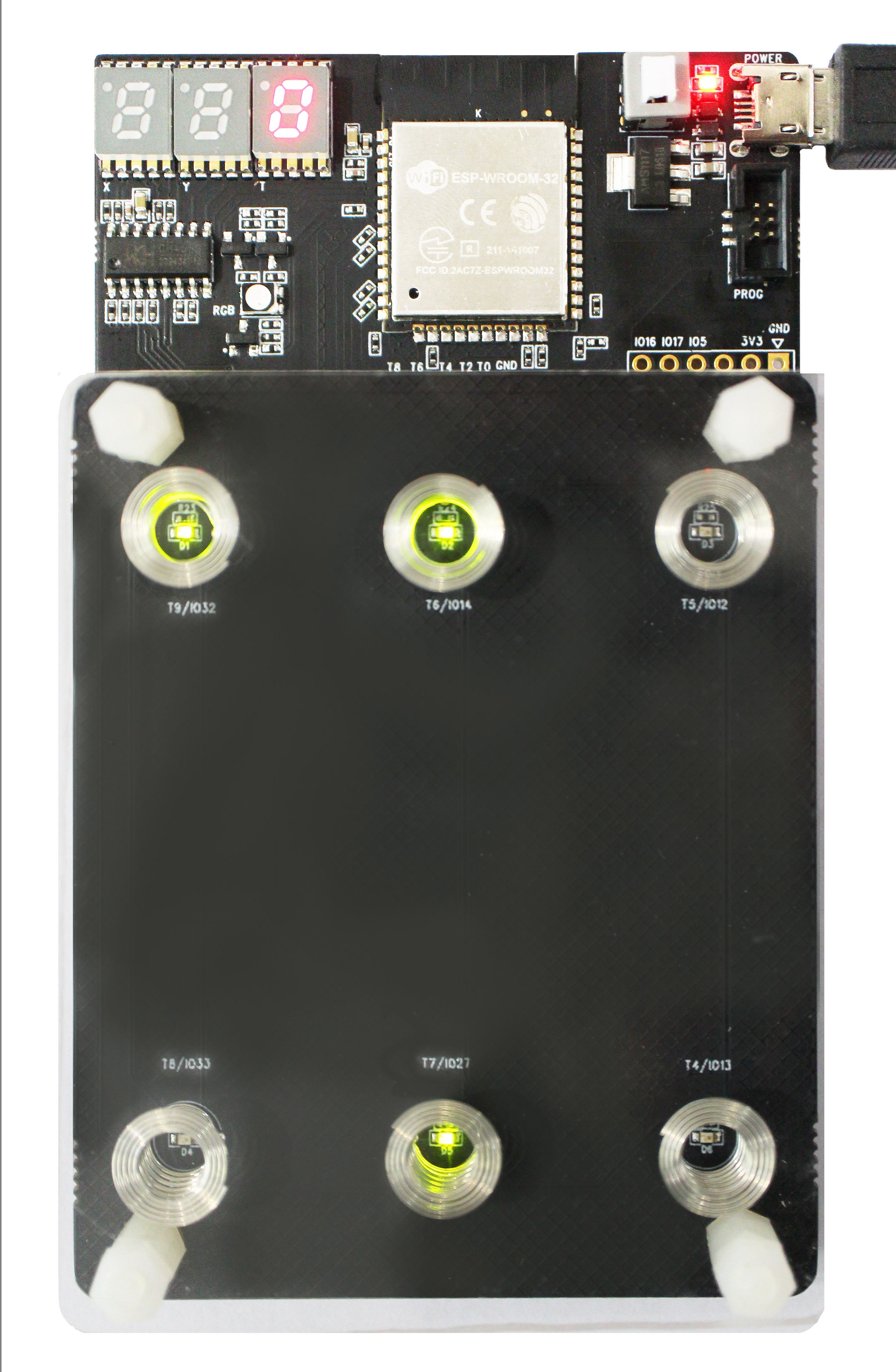
Spring Button |
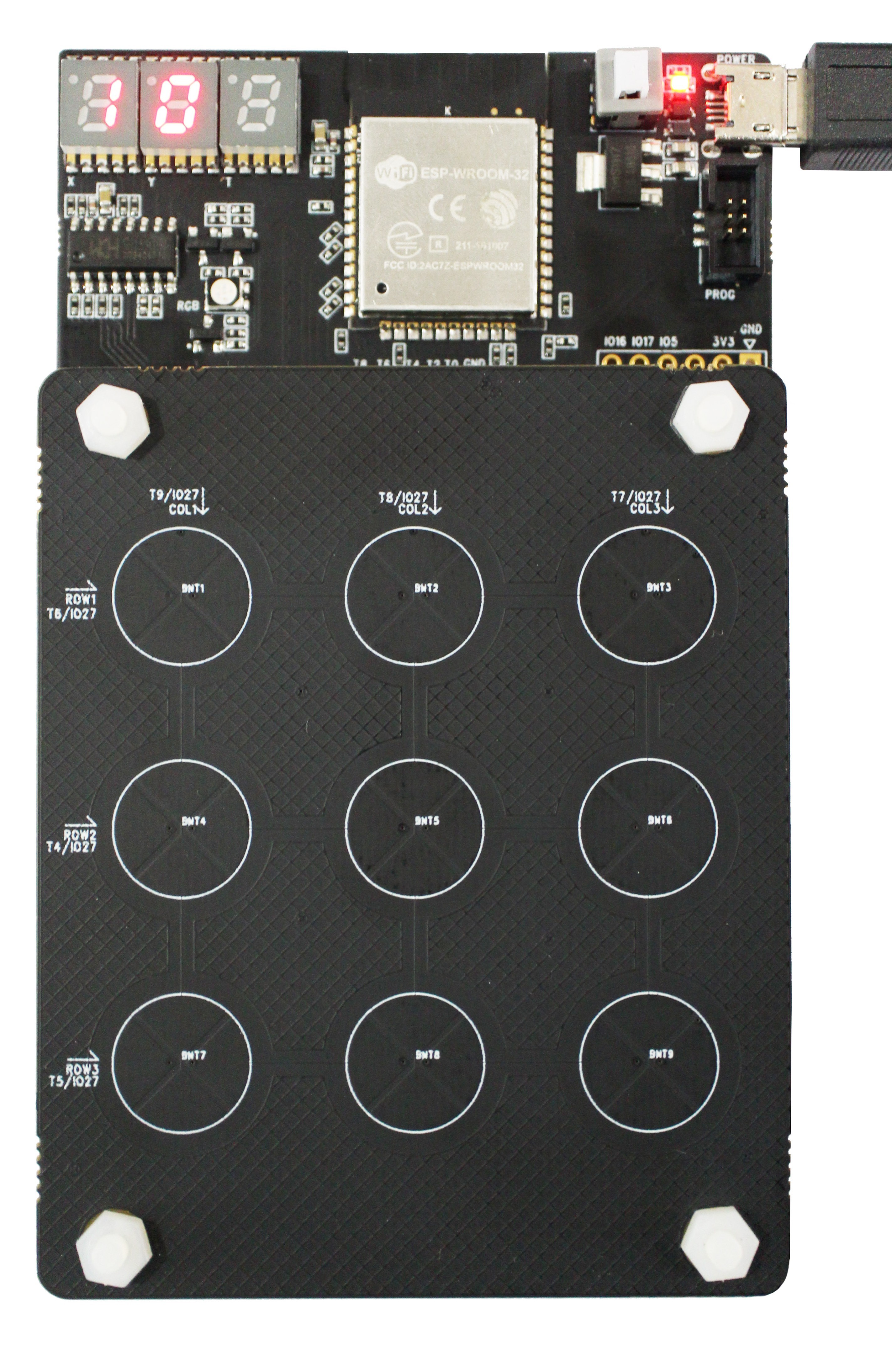
Matrix Button |
|
|
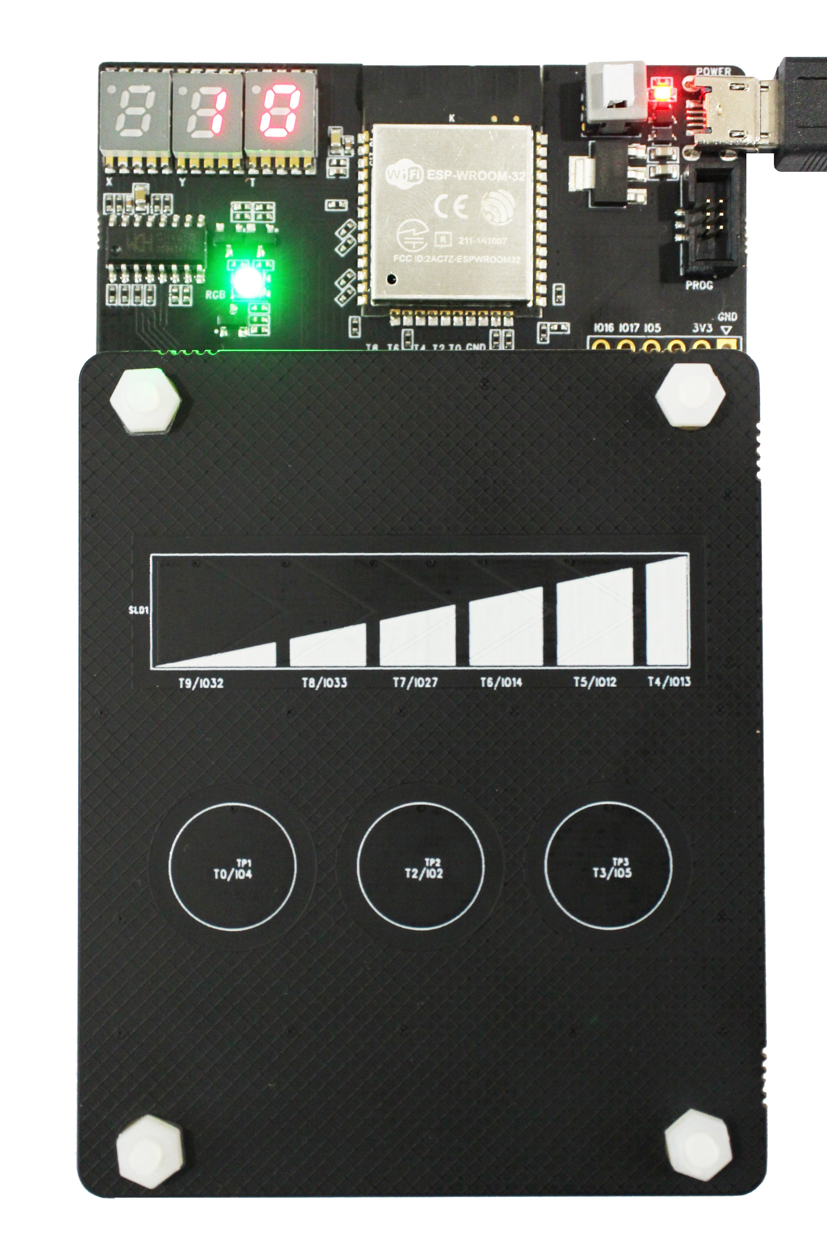
Linear Slider |
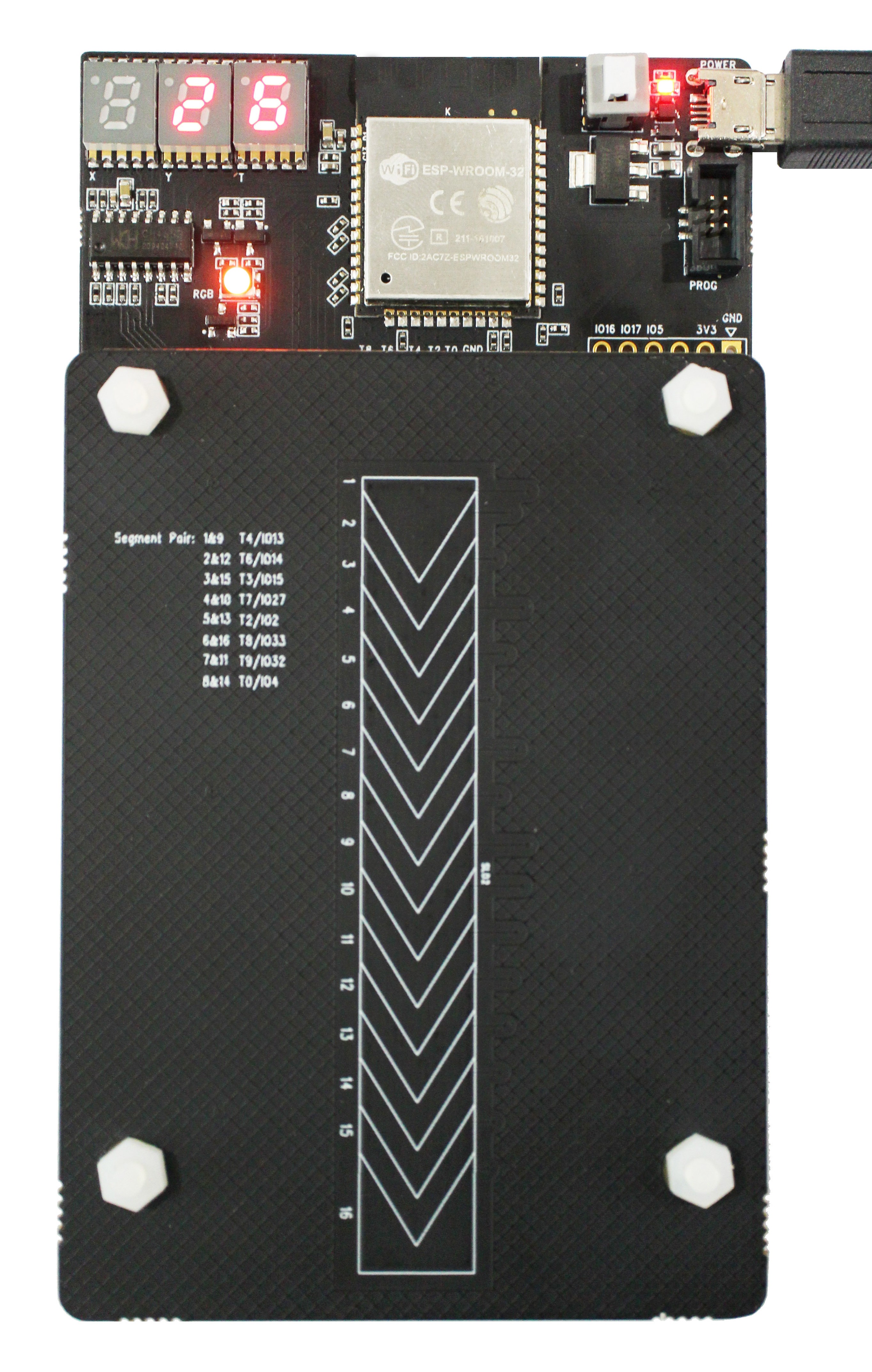
Duplex Slider |
|
|
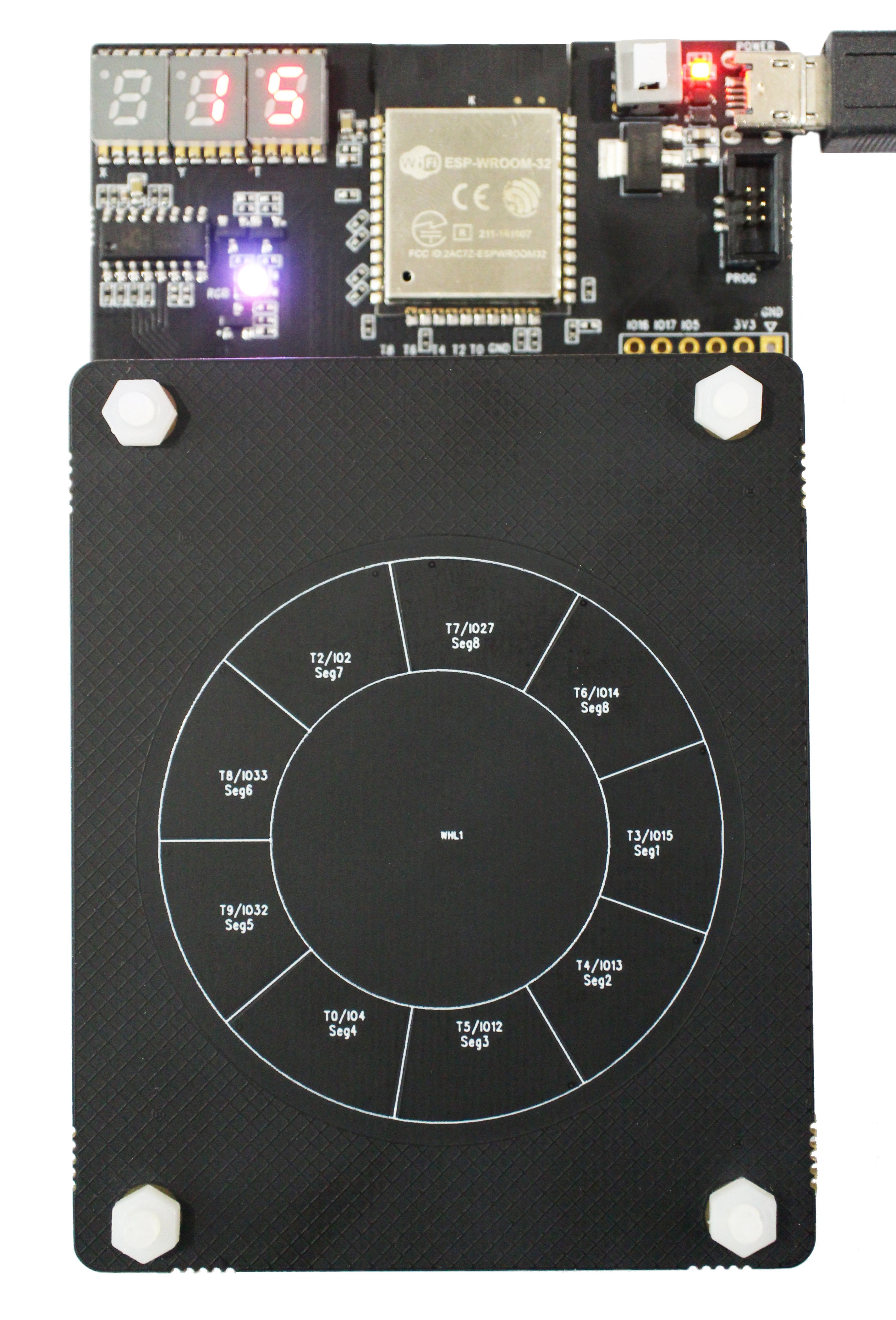
Wheel Slider |