ESP32-S3-LCD-EV-Board v1.5
Note
Please check the version number of your ESP32-S3-LCD-EV-Board-MB indicated by the silk marking on the back. For boards of the v1.5 version, please refer to this user guide. For boards of the v1.4 and below versions, please refer to ESP32-S3-LCD-EV-Board v1.4.
Unless otherwise stated, the ESP32-S3-LCD-EV-Board in this document refers to both ESP32-S3-LCD-EV-Board and ESP32-S3-LCD-EV-Board-2.
This user guide will help you get started with ESP32-S3-LCD-EV-Board and will also provide more in-depth information.
The document consists of the following sections:
Board Overview: Overview of the board hardware/software.
Start Application Development: How to set up hardware/software to develop applications.
Hardware Reference: More detailed information about the board’s hardware.
Hardware Revision Details: This is the first revision of this board released.
Sample Request: How to get a sample board.
Related Documents: Links to related documentation.
Disclaimer and Copyright Notice: Link to the disclaimer and copyright notice.
Board Overview
ESP32-S3-LCD-EV-Board is an ESP32-S3-based development board with a touchscreen. Together with different subboards, ESP32-S3-LCD-EV-Board can drive LCDs with IIC, SPI, 8080, and RGB interfaces. It houses dual array microphones, supports voice recognition and near/far-field voice wake-up, and features screen and voice interaction. The board caters to development needs for touchscreen products with different resolutions and interfaces.
Currently, we have two boards available:
ESP32-S3-LCD-EV-Board with 480x480 LCD
ESP32-S3-LCD-EV-Board-2 with 800x480 LCD

ESP32-S3-LCD-EV-Board with 480x480 LCD

ESP32-S3-LCD-EV-Board-2 with 800x480 LCD
Feature List
The main features of the board are listed below:
Module Embedded: ESP32-S3-WROOM-1 module with 16 MB flash and 16 MB PSRAM
Display: Compatibility with various subboards and support for displays with
RGB,8080,SPI, andI2Cinterfaces. Please refer to LCD Subboards for more informationAudio: Audio Codec + ADC amplifier and dual microphones
USB: USB to serial port chip plus USB Type-C download/debug
Block Diagram
The block diagram below shows the components of ESP32-S3-LCD-EV-Board and their interconnections.

ESP32-S3-LCD-EV-Board Block Diagram (Click to Enlarge)
Description of Components
The ESP32-S3-LCD-EV-Board consists of a mainboard and a subboard (see LCD Subboards for options). Additionally, it allows for a selection of a USB Type-A adapter.
Mainboard
ESP32-S3-LCD-EV-Board-MB is the core of the kit, which integrates the ESP32-S3-WROOM-1 module and provides ports for connection to the LCD subboard.
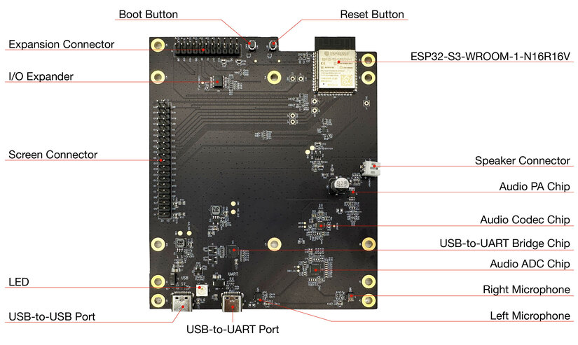
ESP32-S3-LCD-EV-Board-MB - Front (Click to Enlarge)
The key components of the board are described in a counter-clockwise direction.
Key Component |
Description |
|---|---|
ESP32-S3-WROOM-1-N16R16V Module |
ESP32-S3-WROOM-1-N16R16V is a generic Wi-Fi + Bluetooth LE MCU module that is built around the ESP32-S3 series of SoCs. It is integrated with 16 MB flash and 16 MB PSRAM. On top of a rich set of peripherals, the acceleration for neural network computing and signal processing workloads provided by the SoC makes the module an ideal choice for a wide variety of application scenarios related to Artificial Intelligence of Things (AIoT). |
Reset Button |
Press this button to reset the system. |
Boot Button |
Holding down the Boot key and momentarily pressing the Reset key initiates the firmware upload mode. Then you can upload firmware through the serial port or USB. |
Expansion Connector |
Provides connections for all I/O expander pins, all power supply pins, and some module pins. |
I/O Expander |
TCA9554 is a device that provides 8 bits of general purpose parallel I/O expansion. It controls the I/O mode and level via two-line bidirectional I2C bus, offering a simple solution when additional I/Os are needed. |
LCD Board Connector |
Three different types of LCD subboards can be connected via connectors with 2.54 mm pitch. |
LED |
Supports configuring the RGB LED display to indicate status or behavior. |
USB-to-USB Port |
Provides power to the entire system (choose either USB-to-USB or USB-to-UART port). It is recommended to use at least a 5V/2A power adapter to ensure stable power supply. Used for USB communication between the PC and the ESP32-S3-WROOM-1 module. |
USB-to-UART Port |
Provides power to the entire system (choose either USB-to-USB or USB-to-UART port). It is recommended to use at least a 5V/2A power adapter to ensure stable power supply. Used for serial communication between the PC side and the ESP32-S3-WROOM-1 module. |
Left Microphone |
On-board microphone, connected to Audio ADC Chip. |
Right Microphone |
On-board microphone, connected to Audio ADC Chip. |
Audio ADC Chip |
ES7210 is a high performance, low power 4-channel audio ADC for applications of microphone arrays. Featuring Acoustic Echo Cancellation (AEC), it is an ideal choice for music and voice applications. |
USB-to-UART Bridge Controller |
CP2102N, the single-chip USB-to-UART bridge controller, provides up to 3 Mbps connection for software download and debugging. |
Audio Codec Chip |
ES8311 is a low-power mono audio codec that includes a single-channel ADC and DAC, low noise pre-amplifier, headphone driver, digital audio, analog mixing, and gain function. It connects to the ESP32-S3-WROOM-1 module via I2S and I2C buses to process audio through hardware instead of the audio application. |
Audio Amplifier |
NS4150 is a low EMI, 3 W mono class D audio amplifier used to drive speakers by amplifying the audio signal from the audio codec chip. |
Speaker Connector |
External speaker playback is possible with the help of the audio amplifier. |
LCD Subboards
The mainboard can be used together with three different kinds of subboards:
Board Name |
Display (Inch) |
Resolution (Px) |
LCD Driver (Interface) |
Touch Driver |
Available Development Boards |
|---|---|---|---|---|---|
ESP32-S3-LCD-EV-Board-SUB1 v1.0 |
0.96 |
128 x 64 |
SSD1315 (I2C) |
N/A |
Not Available |
2.40 |
320 x 240 |
ST7789V (SPI) |
Not Available |
||
ESP32-S3-LCD-EV-Board-SUB2 v1.5 |
3.50 |
480 x 320 |
ST7796S (8080) |
Not Available |
|
3.95 |
480 x 480 |
GC9503CV (RGB) |
|||
ESP32-S3-LCD-EV-Board-SUB3 v1.3 |
4.30 |
800 x 480 |
ST7262E43 (RGB) |
ESP32-S3-LCD-EV-Board-SUB1 subboard has two interfaces, which support connection to a 2.4-inch display with the SPI interface or a 0.96-inch display with the I2C interface. This board is not yet configured, so it is not further explained here.
ESP32-S3-LCD-EV-Board-SUB2 subboard has two interfaces, which support connection to a display with the RGB interface or a display with the 8080 parallel interface. The current subboard has a 3.95-inch touchscreen with the RGB565 interface and 480x480 resolution. The LCD driver IC is GC9503CV and the touchscreen driver IC is FT5x06.

ESP32-S3-LCD-EV-Board-SUB2 - Front (Click to Enlarge)
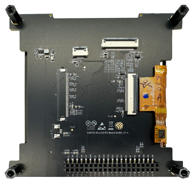
ESP32-S3-LCD-EV-Board-SUB2 - Back (Click to Enlarge)
ESP32-S3-LCD-EV-Board-SUB3 subboard only supports a 4.3-inch touchscreen with the RGB565 interface and 800x480 resolution. The LCD driver IC is ST7262E43 and the touchscreen driver IC is GT1151.

ESP32-S3-LCD-EV-Board-SUB3 - Front (Click to Enlarge)

ESP32-S3-LCD-EV-Board-SUB3 - Back (Click to Enlarge)
USB Type-A Adapter
With the USB Type-A adapter, the mainboard can serve as a USB host for connection to USB devices.

USB Type-A Adapter v1.1 - Front (Click to Enlarge)
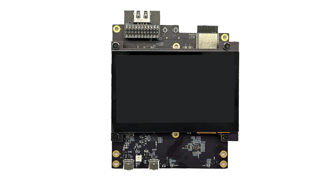
USB Type-A Adapter v1.1 - Connected to the Mainboard (Click to Enlarge)
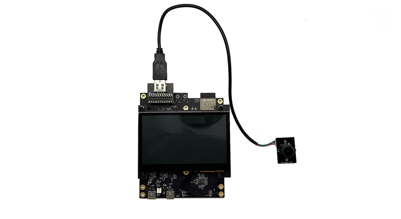
USB Type-A Adapter v1.1 - Connected to USB Devices (Click to Enlarge)
Application Examples
The following application examples are available for ESP32-S3-LCD-EV-Board v1.5:
86-box Demo Example - Demonstrates a GUI demo designed for a control panel (480x480) typically used for wall-mounted 86 type box, providing a smooth graphic operation experience with features like weather report, hot water heater, warm air heater page, and audio output function.
86-box Smart Panel Example - Demonstrates a factory demo for a smart control panel with offline voice recognition function, providing a reference for flashing the board and troubleshooting potential issues.
LVGL Demos Example - Demonstrates how to run LVGL’s demos on an ESP32-S3-LCD-EV-Board, showcasing three methods to avoid tearing effect using different buffering modes, and providing performance testing results for different buffering modes.
Smart Panel Example - Demonstrates a factory demo for a smart control panel with offline voice recognition function, providing instructions on how to flash the example to the ESP32-S3-LCD-EV-Board and configure it for use.
USB Camera LCD Example - Demonstrates how to use an LCD display to show video captured from a USB camera, with options to transfer frames to Wi-Fi and log memory information, providing a basis for developing applications with ESP32-S3-LCD-EV-Board.
USB File System - Demonstrates how to use USB HOST on ESP32-S2/ESP32-S3 to read and write files on a USB flash drive, displaying its contents on the screen, with support for various file formats for preview.
USB Keyboard Example - Demonstrates how to use LCD and LVGL to simulate a USB keyboard on the ESP32-S3-LCD-EV-Board, providing a GUI of a USB keyboard that can interact with a PC like a real keyboard.
For more examples and the latest updates, please refer to the examples folder.
To explore the application examples or to develop your own, please follow the steps outlined in the Start Application Development section.
Start Application Development
This section provides instructions on how to do hardware and software setup and flash firmware onto the board to develop your own application.
Required Hardware
1 x ESP32-S3-LCD-EV-Board-MB
1 x LCD subboard
1 x USB 2.0 cable (standard Type-A to Type-C)
1 x PC (Windows, Linux, or macOS)
Note
Please make sure to use the appropriate USB cable. Some cables can only be used for charging, not for data transfer or program flashing.
Optional Hardware
1 x Speaker
Hardware Setup
Prepare the board for loading of the first sample application:
Connect the LCD subboard to the LCD Board Connector.
Plug in the USB cable to connect the PC with the board.
The LCD lights up and you can start to interact with it.
Now the board is ready for software setup.
Software Setup
The development framework of ESP32-S3-LCD-EV-Board is ESP-IDF. ESP-IDF is a FreeRTOS-based SoC development framework with a bunch of components including LCD, ADC, RMT, and SPI.
To learn how to quickly set up your development environment, please go to Get Started > Installation.
Note
ESP-IDF v5.1.2 is required. It is recommended to use the latest release/v5.1 branch for development.
For more information about developing LCD applications, please refer to ESP-IoT-Solution Programming Guide.
Hardware Reference
This section provides more detailed information about the board’s hardware.
GPIO Allocation
The table below provides the allocation of GPIOs exposed on terminals of ESP32-S3-WROOM-1 module to control specific components or functions of the board.
Pin |
Pin Name |
Function |
|---|---|---|
1 |
GND |
GND |
2 |
3V3 |
Power supply |
3 |
EN |
RESET |
4 |
IO4 |
LED |
5 |
IO5 |
I2S_MCLK |
6 |
IO6 |
I2S_CODEC_DSDIN |
7 |
IO7 |
I2S_LRCK |
8 |
IO15 |
I2S_ADC_SDOUT |
9 |
IO16 |
I2S_SCLK |
10 |
IO17 |
LCD_DE |
11 |
IO18 |
LCD_DATA7 |
12 |
IO8 |
LCD_DATA6 |
13 |
IO19 |
USB_D- |
14 |
IO20 |
USB_D+ |
15 |
IO3 |
LCD_VSYNC |
16 |
IO46 |
LCD_HSYNC |
17 |
IO9 |
LCD_PCLK |
18 |
IO10 |
LCD_DATA0 |
19 |
IO11 |
LCD_DATA1 |
20 |
IO12 |
LCD_DATA2 |
21 |
IO13 |
LCD_DATA3 |
22 |
IO14 |
LCD_DATA4 |
23 |
IO21 |
LCD_DATA5 |
24 |
IO47 |
I2C_SDA |
25 |
IO48 |
I2C_SCL |
26 |
IO45 |
LCD_DATA8 |
27 |
IO0 |
BOOT |
28 |
IO35 |
No connection |
29 |
IO36 |
No connection |
30 |
IO37 |
No connection |
31 |
IO38 |
LCD_DATA9 |
32 |
IO39 |
LCD_DATA10 |
33 |
IO40 |
LCD_DATA11 |
34 |
IO41 |
LCD_DATA12 |
35 |
IO42 |
LCD_DATA13 |
36 |
RXD0 |
UART_RXD0 |
37 |
TXD0 |
UART_TXD0 |
38 |
IO2 |
LCD_DATA14 |
39 |
IO1 |
LCD_DATA15 |
40 |
GND |
GND |
41 |
EPAD |
GND |
The pins on the I/O expander connected to the module can be used for different functions.
IO Expander Pin |
Pin Name |
Function |
|---|---|---|
1 |
A0 |
GND |
2 |
A1 |
GND |
3 |
A2 |
GND |
4 |
P0 |
PA_CTRL |
5 |
P1 |
LCD_SPI_CS |
6 |
P2 |
LCD_SPI_SCK |
7 |
P3 |
LCD_SPI_MOSI |
8 |
GND |
GND |
9 |
P4 |
Free |
10 |
P5 |
Free |
11 |
P6 |
Free |
12 |
P7 |
Free |
13 |
INT |
No connection |
14 |
SCL |
I2C_SCL |
15 |
SDA |
I2C_SDA |
16 |
VCC |
Supply voltage |
Power Distribution
Power Supply over USB
There are two ways to power the development board via USB power port.
Via
USB-to-USBport

ESP32-S3-LCD-EV-Board - USB-to-USB Power Supply
Via
USB-to-UARTport
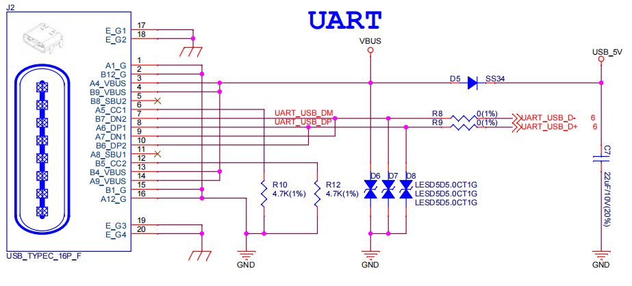
ESP32-S3-LCD-EV-Board - USB-to-UART Power Supply
Independent Audio and Digital Power Supply
ESP32-S3-LCD-EV-Board features independent power supplies for the audio components and ESP module. This should reduce noise in the audio signal from digital components and improve the overall performance of the components.

ESP32-S3-LCD-EV-Board - Digital Power Supply

ESP32-S3-LCD-EV-Board - Audio Power Supply
AEC Path
The acoustic echo cancellation (AEC) path provides reference signals for AEC algorithm.
ESP32-S3-LCD-EV-Board provides two compatible echo reference signal source designs. One is Codec (ES8311) DAC output (DAC_AOUTLP/DAC_AOUTLP), the other is PA (NS4150) output (PA_OUT+/PA_OUT+). The former is a default and the recommended selection. Resistors R54 and R56 shown in the figure below should not be installed.
The echo reference signal is collected by ADC_MIC3P/ADC_MIC3N of ADC (ES7210) and then sent back to ESP32-S3 for AEC algorithm.

ESP32-S3-LCD-EV-Board - AEC Codec DAC Output (Click to Enlarge)

SP32-S3-LCD-Ev-Board - AEC PA Output (Click to Enlarge)

ESP32-S3-LCD-EV-Board - AEC Reference Signal Collection (Click to Enlarge)
Hardware Setup Options
Automatic Download
There are two ways to put the development board into the download mode.
Press the Boot and Reset buttons. Release the Reset button first and then the Boot button.
The download is performed automatically by the software. The software uses the DTR and RTS signals from the serial port to control the status of the EN and IO0 pins.
Hardware Revision Details
ESP32-S3-LCD-EV-Board v1.5
The following pins are re-allocated for the ESP32-S3-WROOM-1-N16R16V module:
I2C_SCL: fromIO18toIO48I2C_SDA: fromIO8toIO47LCD_DATA6: fromIO47toIO8LCD_DATA7: fromIO48toIO18
Level-shifting circuits are added to
IO47andIO48for converting the 1.8 V logic level to a 3.3 V logic level.
ESP32-S3-LCD-EV-Board v1.4
Sample Request
This development board with the USB Type-A adapter is suitable for evaluating Espressif’s high-performance HMI Smart Displays Solution. For placing orders, please proceed to the Espressif Online Shop.