Reference Documentation
Introduction to Functions
The Working Mode of USB Bridge
ESP-Prog uses FT2232HL, which is provided by FTDI, as its USB Bridge Controller chip. The board can be configured to convert the USB 2.0 interface to serial and parallel interfaces that support a wide range of industry standards. ESP-Prog uses FT2232HL’s default dual-asynchronous serial interface mode available after installing the FT2232HL chip driver on their PCs.
Note
The PC is able to identify the ESP-Prog’s two ports by their port numbers. The bigger port number represents the Program interface, while the other one represents the JTAG interface.
Communication Interface
ESP-Prog can connect to ESP32 user boards using both the Program interface and the JTAG interface.
Program Interface
The Program interface has six pins, including the UART interface (ESP_TXD, ESP_RXD), boot mode selection pin (ESP_IO0) and reset pin (ESP_EN). The design for the Program interface on the user board should follow the reference provided in the figure below.

Program Interface (click to enlarge)
JTAG Interface
The design for the JTAG interface on the user board should follow the reference provided in the figure below.

JTAG Interface (click to enlarge)
Fool-proof Design
The ESP-Prog board uses header connectors (DC3-6P/DC3-10P) which support reverse-current circuitry protection. In such cases, it is recommended that users also use header connectors on their user boards, such as
FTSH-105-01-S-DV-*orDC3-*P.
Note
Keying of the plugs and sockets to insert the plug is in one specific orientation, which means each socket of ESP-Prog corresponds to the plugs on the cable and using a mismatched cable might lead to a wrong order of connection. Please use the cables provided by Espressif.
Automatic Downloading Function
ESP-Prog supports automatic downloading. After connecting the Program interface of ESP-Prog to the user board, the downloading program can download data or run programs automatically by controlling the states of the start-mode selection pin (ESP_IO0) and reset pin (ESP_EN), which spares the users from manually restarting the device and selecting the downloading modes. The two buttons on the ESP-Prog board enable users to reset and control the boot mode of the device manually.
The schematics of the automatic downloading circuit is displayed below.
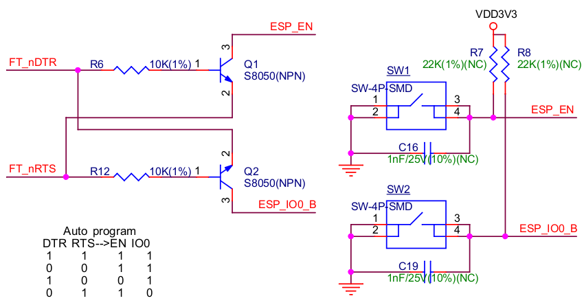
Automatic Downloading Circuit (click to enlarge)
Delay Circuit
The delay circuit of ESP-Prog includes the bus buffer, inverter, MOSFET, first-order RC circuit, and other components. This delay circuit ensures that the ESP32 chip can power up or reset itself before connecting with the JTAG signal, thus protecting the chip from the influence of JTAG on power-up or reset.
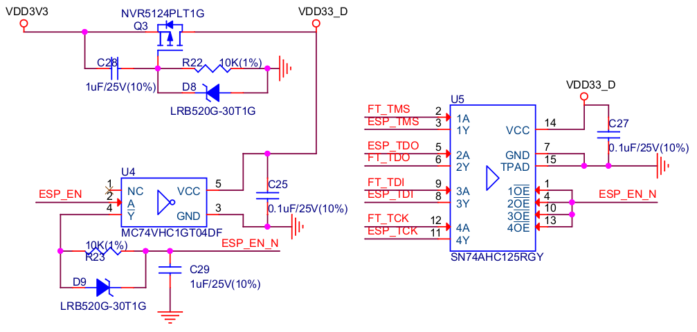
ESP-Prog Delay Circuit (click to enlarge)
LED Status Indication
The red LED lights up when the system is connected to the 3.3 V power.
The green LED lights up when ESP-Prog is downloading data to ESP32.
The blue LED lights up when ESP-Prog is receiving data from ESP32.
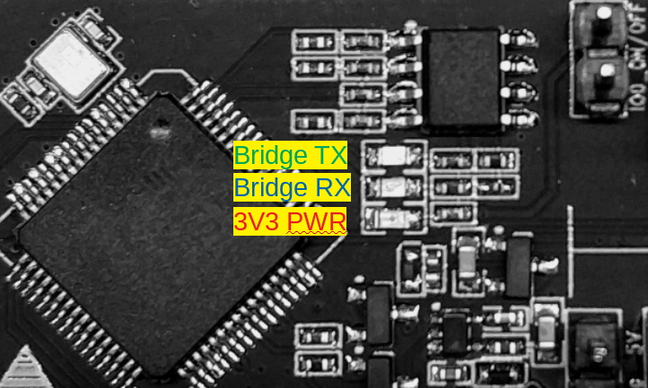
LED Status (click to enlarge)
Pin Headers
Users can select the power supply for the Program and JTAG interfaces via the Pin Header to Select Power Supply, and select the boot modes of ESP8266 and ESP32 via the IO0 On/Off Pin.
Pin Header to Select Power Supply
The pin header in the middle is the power input pin for each interface. When this pin is connected to 5 V, the power output of the interface is 5 V. When this pin is connected to 3.3 V, the power output of the interface is 3.3 V.
IO0 On/Off Pin
Pin IO0 can be set to select ESP8266’s and ESP32’s boot modes. This pin can be used as a common GPIO, after the chip is powered on. By removing a jumper from the pin header, users can disconnect Pin IO0 manually to protect the operation of the user board from the influence of ESP-Prog’s automatic downloading circuit.
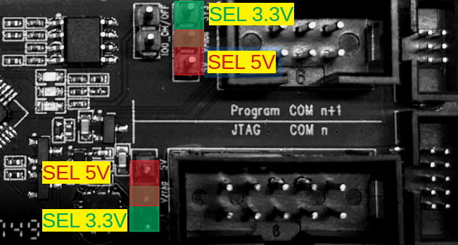
Pin Headers (click to enlarge)
For further design documentation for the board, please contact us at sales@espressif.com.