USB-Serial-JTAG Peripheral Introduction
The ESP32-S3/C3 chips come with a built-in USB-Serial-JTAG peripheral, which includes a USB-to-serial converter and a USB-to-JTAG converter. It supports connection to a PC via a USB cable, enabling functions such as firmware downloading, debugging, and printing system logs. The internal structure of the USB-Serial-JTAG peripheral can be referred to in the ESP32-C3 Technical Reference Manual - USB Serial/JTAG Controller.
USB-Serial-JTAG peripheral driver
For Linux and MacOS systems, No need to manually install drivers.
For Windows 10 and above, drivers will be automatically installed when connected to the internet.
For Windows 7/8 systems, manual driver installation is necessary. The driver can be downloaded from: esp32-usb-jtag-2021-07-15. Alternatively, users can use the ESP-IDF Windows Installer, selecting the USB-Serial-JTAG driver during installation.
USB-Serial-JTAG peripheral built-in functionality
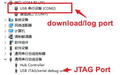
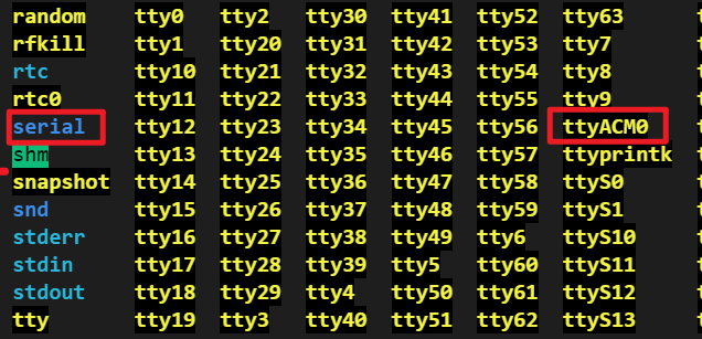
Upon connecting the USB-Serial-JTAG peripheral to a PC, the Device Manager will show the addition of two devices:
For Windows as shown in the following figure:

For Linux as shown in the following figure:

Use USB-Serial-JTAG to download firmware
By default, the USB-Serial-JTAG download function is enabled. You can directly connect it to the PC using a USB cable and then use the esptool tool (or directly use idf.py flash) to configure the serial port corresponding to the USB-Serial-JTAG device (COM* for Windows, /dev/ttyACM* for Linux, /dev/cu* for MacOS) for firmware download. During the download process, esptool automatically resets the device and switches it to download mode through the USB control protocol.
If the USB pins corresponding to USB-Serial-JTAG are used for other functions in the application, such as being used as a regular GPIO or other peripheral IO, USB-Serial-JTAG will be unable to establish a connection with the USB host. Therefore, it cannot switch the device to download mode via USB. In such cases, users must manually switch the device to download mode using the Boot control pin and then use esptool for firmware download.
To avoid using the USB pins corresponding to USB-Serial-JTAG for other functions in the application, which would prevent automatic entry into download mode via USB, users need to expose the Boot control pin in hardware design.
By default, when downloading different chips through the USB interface, the COM number will increment, which may cause inconvenience for mass production. Users can refer to Prevent Windows from incrementing COM numbers based on USB device serial number for a solution.
Debugging code using USB-Serial-JTAG
The USB-Serial-JTAG supports debugging code through the JTAG interface. Users only need to connect it to the PC using a USB cable and then use the OpenOCD tool for code debugging. Please refer to the configuration guide for setting up the built-in JTAG interface on ESP32-C3 at: Configure Built-in JTAG Interface on ESP32-C3.
Print system LOG using USB-Serial-JTAG
Users can enable the USB-Serial-JTAG LOG feature by configuring the state in
menuconfig-> Component config → ESP System Settings → Channel for console secondary output.Once the LOG feature is enabled, you can connect the device directly to the PC using a USB cable and then use
idf.py monitoror other serial port tools to open the serial port corresponding to the USB-Serial-JTAG device (COM*for Windows,/dev/ttyACM*for Linux,/dev/cu*for MacOS) to print system logs.The
USB-Serial-JTAGwill only print logs after the host is connected. If the host is not connected,USB-Serial-JTAGwill not be initialized, and logs will not be printed.The LOG feature of
USB-Serial-JTAGcannot be used in sleep modes (including deep sleep and light sleep modes). If it is necessary to print logs in sleep mode, theUARTinterface can be used.
Using USB-Serial-JTAG pins as normal GPIO
If users need to use the USB pins corresponding to USB-Serial-JTAG for other functions in the application, such as using them as regular GPIO, it is important to note that the USB D+ interface has a default pull-up resistor, which keeps the USB D+ pin at a high level. Therefore, it is necessary to disable this pull-up resistor when using it as a GPIO.
Starting from ESP-IDF v4.4, the GPIO driver defaults to disabling the USB D+ pull-up resistor. Users do not need additional configuration when using the GPIO driver.
Users can also modify the register value
USB_SERIAL_JTAG.conf0.dp_pullup = 0;to disable the USB D+ pull-up resistor.
It is important to note that the pull-up resistor on the USB D+ pin is present at power-up. Before software disables the pull-up resistor, the USB D+ pin has already been pulled high, causing it to be in a high-level state during the initial phase when used as a GPIO. If users need the USB D+ pin to be immediately low after power-up, it is necessary to design the hardware to pull down the USB D+ pin through an external circuit.