Hardware Connection
This document introduces what hardware you need to prepare and how to connect them in order to download AT firmware, send AT commands, and receive AT responses.
The commands supported by each series of AT firmware vary, and its compatibility with modules or chips also differs. For more information, refer to ESP-AT Firmware Differences.
If you don’t want to use the default AT pin, you can refer to the How to Set AT Port Pins document to change the pin.
What You Need
Component |
Function |
|---|---|
ESP32 board |
Slave MCU. |
USB cable (connects ESP32 board to the PC) |
Download/Log output connection. |
PC |
Act as Host MCU. Download firmware to Slave MCU. |
USB cable (connects the PC to the USB-to-UART converter) |
AT command/response connection. |
USB-to-UART converter |
Convert between USB signals and TTL signals. |
Jumper wires (connects the USB-to-UART converter to ESP32 board) |
AT command/response connection. |
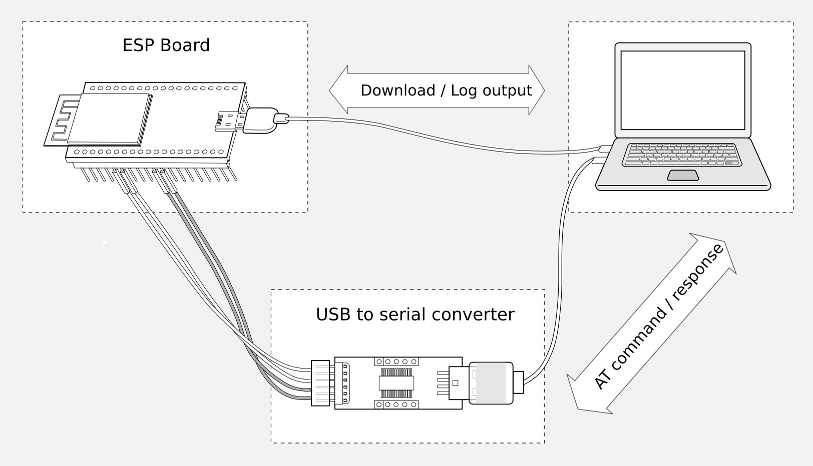
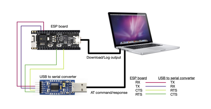
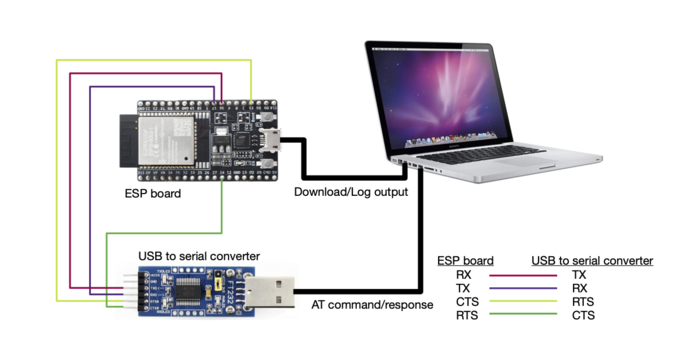
Connection of Components for ESP-AT Testing
Note:
In the above picture, four jump wires are used to connect the ESP32 board and USB-to-UART converter. If you do not use hardware flow control, two wires connecting TX/RX and a simpler converter will be enough.
If you use an ESP32 module (instead of a development board) and flash firmware via UART, you need to:
Reserve the U0RXD and U0TXD pins (refer to Datasheet > Pin Overview)
Reserve the strapping pins (refer to Datasheet > Boot Configurations), enter download mode by controlling the strapping pin level
For more details, please refer to ESP32 Hardware Requirements for Entering Download Mode
ESP32 Series
ESP32 AT uses two UART ports: UART0 is used to download firmware and log output; UART1 is used to send AT commands and receive AT responses. Both UART0 and UART1 use 115200 baud rate for communication by default.
All ESP32 modules use GPIO1 and GPIO3 as UART0, but they use different GPIOs as UART1. The following sections illustrate which GPIOs you should connect for each ESP32 series of modules.
For more details of ESP32 modules and boards, please refer to ESP32 modules and ESP32 boards.
ESP32-WROOM-32 Series
Function of Connection |
ESP32 Board or Module Pins |
Other Device Pins |
|---|---|---|
Download/Log output 1 |
|
|
AT command/response 2 |
|
|
Note 1: Connection between individual pins of the ESP32 board and the PC is already established internally on the ESP32 board. You only need to provide USB cable between the board and PC.
Note 2: CTS and RTS pins are required only when hardware flow control is enabled.
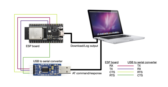
ESP32-WROOM-32 Series Hardware Connection
If you want to connect your device directly with ESP32-WROOM-32 rather than the ESP32 board that integrates it, please refer to ESP32-WROOM-32 Datasheet for more details.
ESP32-MINI-1 Series
Function of Connection |
ESP32 Board or Module Pins |
Other Device Pins |
|---|---|---|
Download/Log output 1 |
|
|
AT command/response 2 |
|
|
Note 1: Connection between individual pins of the ESP32 board and the PC is already established internally on the ESP32 board. You only need to provide USB cable between the board and PC.
Note 2: CTS and RTS pins are required only when hardware flow control is enabled.
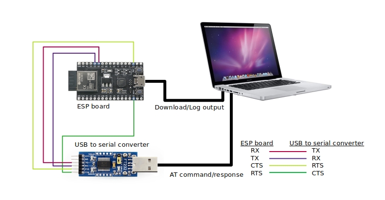
ESP32-MINI-1 Series Hardware Connection
ESP32-WROVER Series
Function of Connection |
ESP32 Board or Module Pins |
Other Device Pins |
|---|---|---|
Download/Log output 1 |
|
|
AT command/response 2 |
|
|
Note 1: Connection between individual pins of the ESP32 board and the PC is already established internally on the ESP32 board. You only need to provide USB cable between the board and PC.
Note 2: CTS and RTS pins are required only when hardware flow control is enabled.
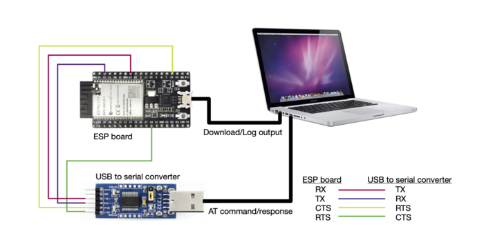
ESP32-WROVER Series Hardware Connection
If you want to connect your device directly with ESP32-WROVER rather than the ESP32 board that integrates it, please refer to ESP32-WROVER Datasheet for more details.
ESP32-PICO Series
Function of Connection |
ESP32 Board or Module Pins |
Other Device Pins |
|---|---|---|
Download/Log output 1 |
|
|
AT command/response 2 |
|
|
Note 1: Connection between individual pins of the ESP32 board and the PC is already established internally on the ESP32 board. You only need to provide USB cable between the board and PC.
Note 2: CTS and RTS pins are required only when hardware flow control is enabled.
ESP32-PICO Series Hardware Connection
If you want to connect your device directly with ESP32-PICO-D4 rather than the ESP32 board that integrates it, please refer to ESP32-PICO-D4 Datasheet for more details.
ESP32-SOLO Series
Function of Connection |
ESP32 Board or Module Pins |
Other Device Pins |
|---|---|---|
Download/Log output 1 |
|
|
AT command/response 2 |
|
|
Note 1: Connection between individual pins of the ESP32 board and the PC is already established internally on the ESP32 board. You only need to provide USB cable between the board and PC.
Note 2: CTS and RTS pins are required only when hardware flow control is enabled.
ESP32-SOLO Series Hardware Connection
If you want to connect your device directly with ESP32-SOLO-1 rather than the ESP32 board that integrates it, please refer to ESP32-SOLO-1 Datasheet for more details.