Rust ESP Board
Welcome to the Rust ESP Development board project. This repository contains everything you will need to build the board yourself.
Where to buy
(Note that at least when ordering from the UK and seemingly EU and Europe, if you choose to order through Mouser there is long process instigated by email post-checkout to fill out and then electronically sign or fax export declaration forms which can add significant delay)
Ferrous Systems Training
Project Specification
This board is based on the ESP32-C3, and includes sensors, LEDs, buttons, a battery charger, and USB type-C connector.
SoC Features
IEEE 802.11 b/g/n-compliant
Bluetooth 5, Bluetooth mesh
32-bit RISC-V single-core processor, up to 160MHz
384 KB ROM
400 KB SRAM (16 KB for cache)
8 KB SRAM in RTC
22 × programmable GPIOs
3 × SPI
2 × UART
1 × I2C
1 × I2S
2 × 54-bit general-purpose timers
3 × watchdog timers
1 × 52-bit system timer
Remote Control Peripheral (RMT)
LED PWM controller (LEDC)
Full-speed USB Serial/JTAG controller
General DMA controller (GDMA)
1 × TWAI®
2 × 12-bit SAR ADCs, up to 6 channels
1 × temperature sensor
For the complete description, see the ESP32-C3 Datasheet.
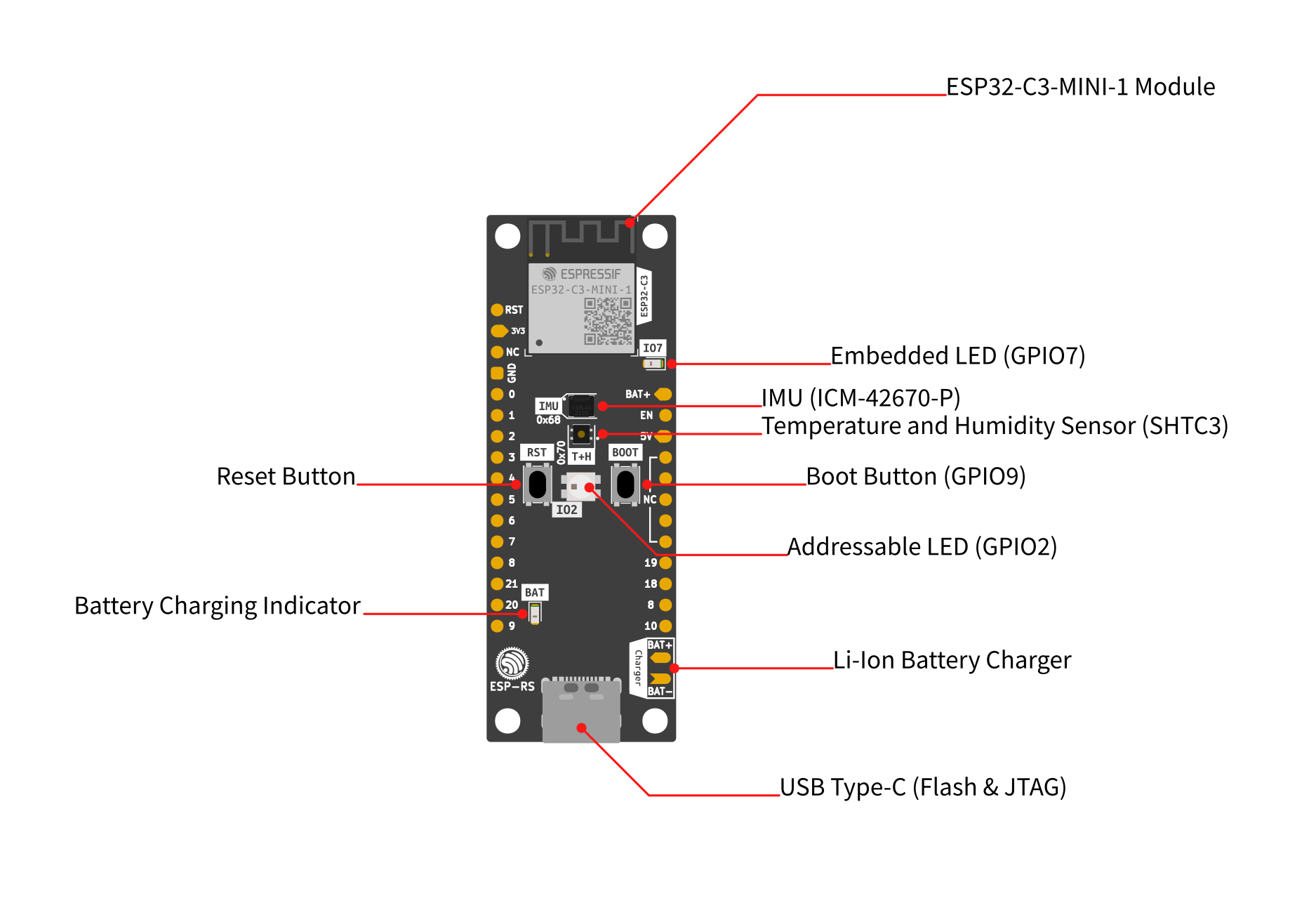
Diagram
I2C Peripherals
This board includes the following peripherals over the I2C bus:
Peripheral |
Part number |
Reference |
Create |
Address |
|---|---|---|---|---|
IMU |
ICM-42670-P |
0x68 |
||
Temperature and Humidity |
SHTC3 |
0x70 |
I2C Bus Connection
Signal |
GPIO |
|---|---|
SDA |
GPIO10 |
SCL |
GPIO8 |
I/Os
The following devices are connected through GPIO:
I/O Devices |
GPIO |
|---|---|
WS2812 LED |
GPIO2 |
LED |
GPIO7 |
Button/Boot |
GPIO9 |
Power
USB type-C (no PD compatibility).
Li-Ion battery charger - MCP73831T-2ACI/OT, it charges up to 4.2V.
Recommendation: MCP73831T-2ACI/OT does not provide battery protection for over-current or over-discharge. For the battery (Li-Ion or Li-Po), it’s recommended the ones with embedded protection
Limitation: reading the battery voltage is not supported.
Pin Layout
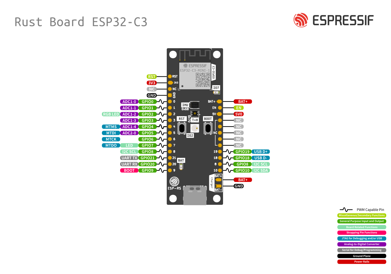
Pin Layout
Left Side
Pin Number |
Description |
SoC |
|---|---|---|
1 |
Reset |
EN/CHIP_PU |
2 |
3V3 |
|
3 |
N/C |
|
4 |
GND |
|
5 |
IO0/ADC1-0 |
GPIO0 |
6 |
IO1/ADC1-1 |
GPIO1 |
7 |
IO2/ADC1-2 |
GPIO2 |
8 |
IO3/ADC1-3 |
GPIO3 |
9 |
IO4/ADC2-0 |
GPIO4 |
10 |
IO5/ADC2-1 |
GPIO5 |
11 |
IO6/MTCK |
GPIO6 |
12 |
IO7/MTDO/LED |
GPIO7 |
13 |
IO9/LOG |
GPIO8 |
14 |
IO21/U0RXD |
GPIO21 |
15 |
IO20/U0TXD |
GPIO20 |
16 |
IO9/BOOT |
GPIO9 |
Right Side
Pin Number |
Description |
SoC |
|---|---|---|
1 |
VBAT |
|
2 |
EN [1] |
|
3 |
VBUS [2] |
|
4 |
NC |
|
5 |
NC |
|
6 |
NC |
|
7 |
NC |
|
8 |
NC |
|
9 |
IO18/USB_D- |
GPIO18 |
10 |
IO19/USB_D+ |
GPIO19 |
11 |
IO8/SCL |
GPIO8 |
12 |
IO10/SDA |
GPIO10 |
Project KiCad Libraries
Board Design
Top
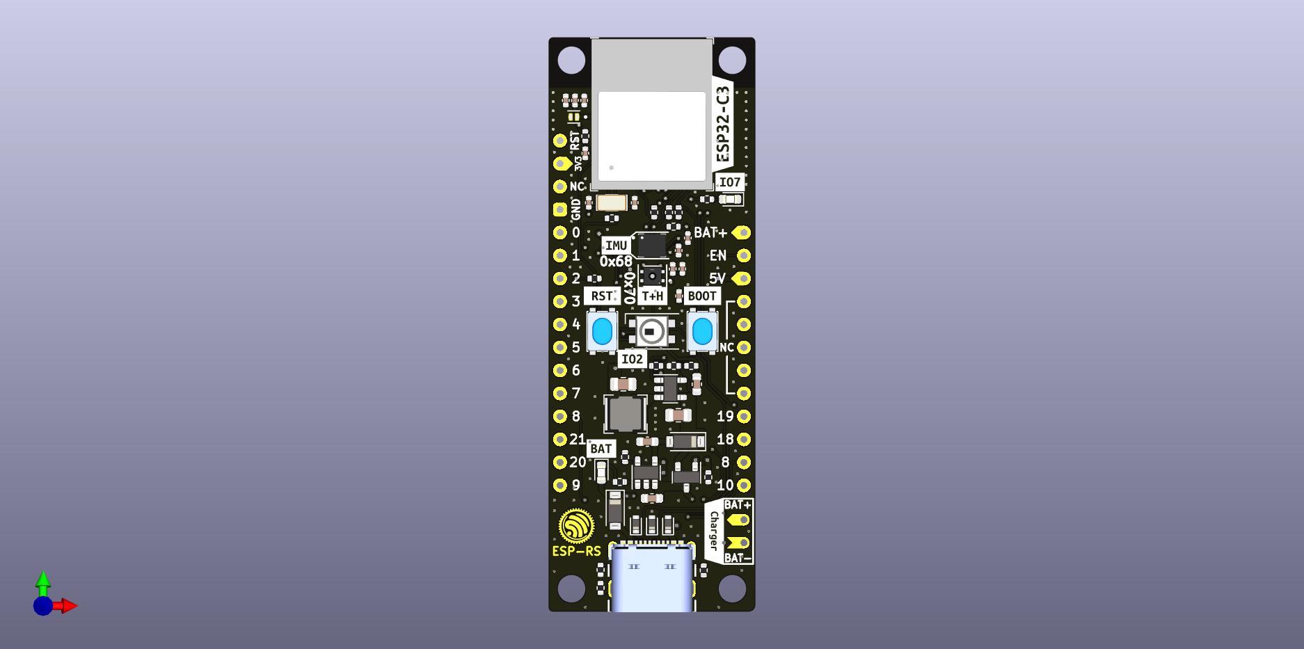
TOP
Bottom
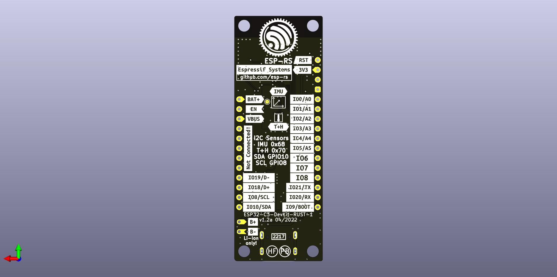
BOT