ESP32-C3-DevKit-RUST-2

[中文]

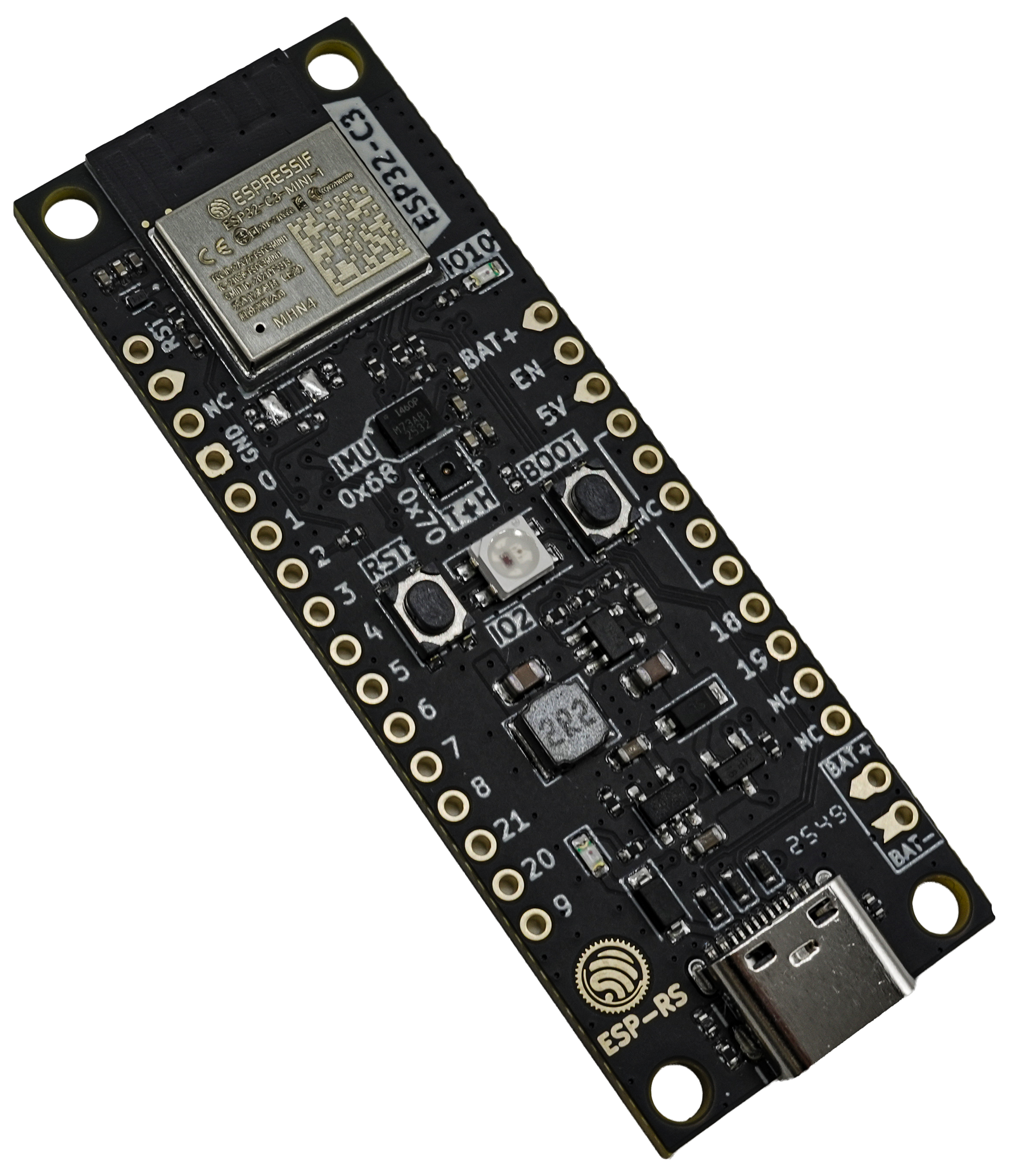
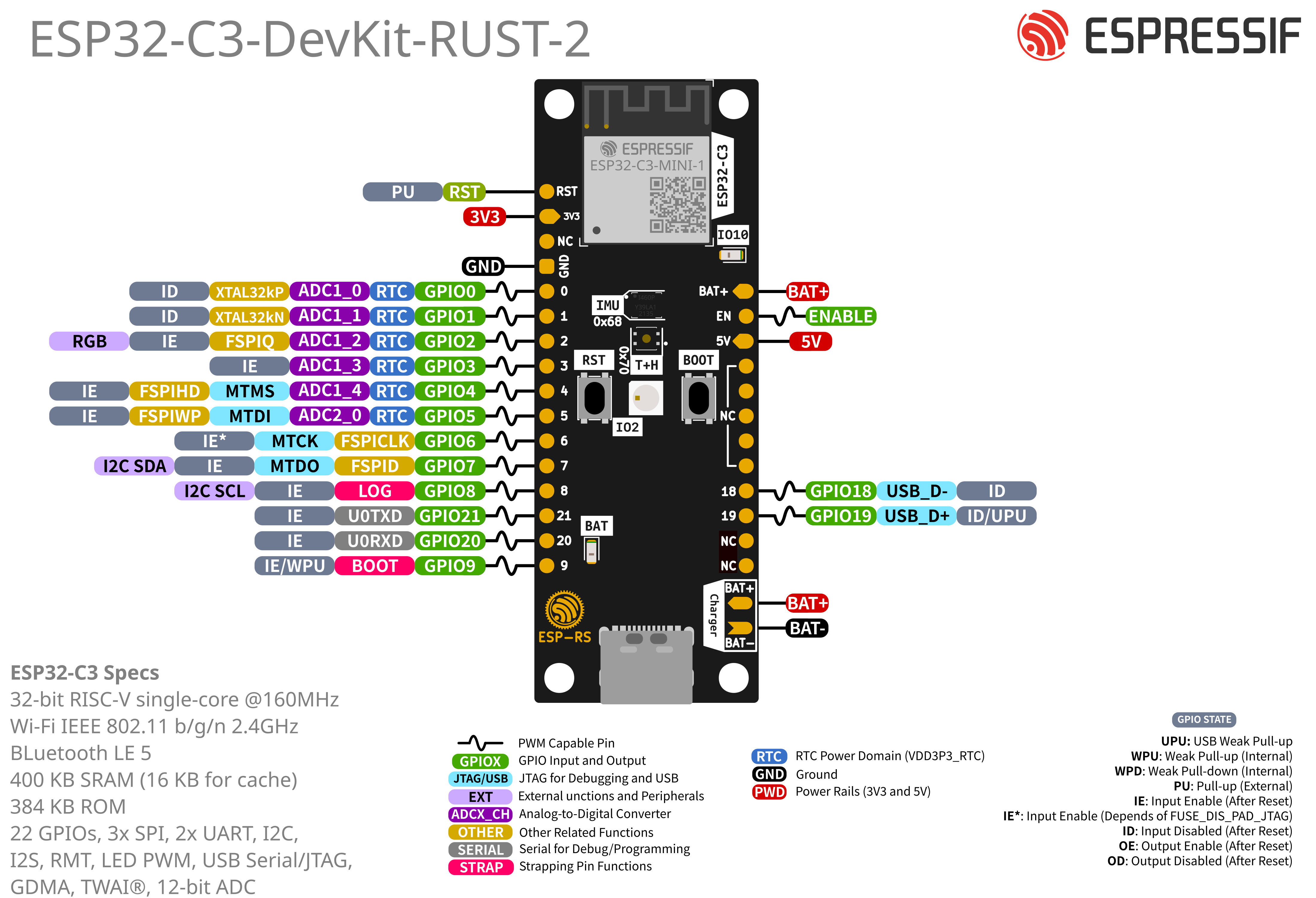
This user guide is intended to help you get started with the ESP32-C3-DevKit-RUST-2 and to provide more detailed technical information for development and integration. The ESP32-C3-DevKit-RUST-2 is a development board based on the ESP32-C3-MINI-1 module, a general-purpose module featuring 4 MB of SPI flash. The board integrates full Wi-Fi and Bluetooth® Low Energy (BLE) connectivity, making it suitable for a wide range of IoT and embedded applications.

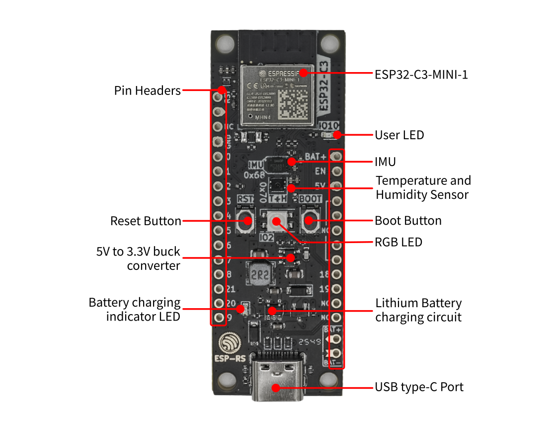
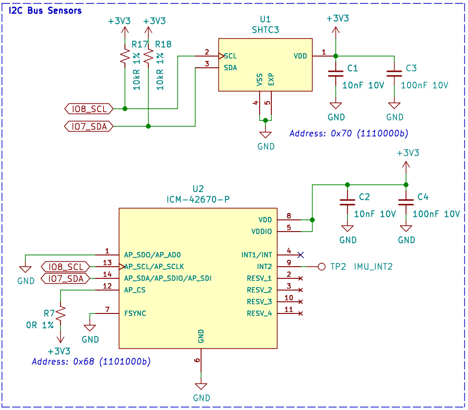
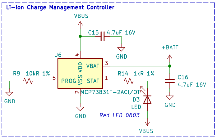
In addition to the ESP32-C3, the board integrates onboard sensors and a Li-Ion battery charging circuit, enabling portable and sensor-based applications without requiring external components.

Most I/O pins are routed to pin headers on both sides of the board, allowing easy access to the ESP32-C3 peripherals. Developers can connect external components using jumper wires or mount the ESP32-C3-DevKit-RUST-2 directly on a breadboard for rapid prototyping.

ESP32-C3-DevKit-RUST-2

ESP32-C3-DevKit-RUST-2

The document consists of the following major sections:

  • Getting Started: Overview of ESP32-C3-DevKit-RUST-2 and hardware/software setup instructions to get started.

  • Hardware Reference: More detailed information about the ESP32-C3-DevKit-RUST-2’s hardware.

  • Hardware Revision Details: Revision history, known issues, and links to user guides for previous versions (if any) of ESP32-C3-DevKit-RUST-2.

  • Related Documents: Links to related documentation.

Getting Started

This section provides a brief introduction of ESP32-C3-DevKit-RUST-2, instructions on how to do the initial hardware setup and how to flash firmware onto it.

Description of Components

ESP32-C3-DevKit-RUST-2 (with the ESP32-C3-MINI-1 module) - front

ESP32-C3-DevKit-RUST-2 (with the ESP32-C3-MINI-1 module) - front

The key components of the board are described starting from the module and continue in the clockwise direction.

Key Component

Description

ESP32-C3-MINI-1

ESP32-C3-MINI-1 is a powerful general-purpose Espressif module that offers Wi-Fi and Bluetooth Low Energy coexistence. It integrates a 4 MB SPI flash.

User LED

User GPIO LED, connected to GPIO10.

IMU

Inertial Measurement Unit (IMU) ICM-42670-P, connected via I2C interface

Temperature and Humidity Sensor

SHTC3, connected via I2C interface

Boot Button

Download button. Holding down Boot and then pressing Reset initiates Firmware Download mode for downloading firmware through the serial port.

RGB LED

Addressable RGB LED, driven by GPIO2.

Lithium Battery charging circuit

Built-in charging circuit for single-cell lithium batteries

USB type-C Port

USB-CDC port. Power supply for the board as well as the communication interface between a computer and the ESP32-C3 chip (flashing and debug).

Battery charging indicator LED

The red LED indicates that the battery is being charged.

5V to 3.3V buck converter

Power regulator that converts a 5 V supply into a 3.3 V output.

Reset Button

Press this button to restart the system.

Pin Headers

Most of the available GPIO pins are broken out to the pin headers for external access. For details, please see Header Block.

Application Examples

The following application examples are available for ESP32-C3-DevKit-RUST-2:

To explore the application examples or to develop your own, please follow the steps outlined in the Start Application Development section.

Start Application Development

Before powering up your ESP32-C3-DevKit-RUST-2, please make sure that it is in good condition with no obvious signs of damage.

Required Hardware

  • ESP32-C3-DevKit-RUST-2

  • USB 2.0 cable (USB Type-C)

  • Computer running Windows, Linux, or macOS

Note

Be sure to use an appropriate USB cable. Some cables are for charging only and do not provide the needed data lines nor work for programming the boards.

Hardware Setup

Connect the board with the computer using the USB type-C Port.

Software Setup

Please proceed to ESP-IDF Get Started, which will quickly help you set up the development environment then flash an application example onto your board.

Contents and Packaging

Retail Orders

If you order a few samples, each ESP32-C3-DevKit-RUST-2 comes in an individual package in either antistatic bag or any packaging depending on your retailer.

For retail orders, please go to https://www.espressif.com/en/contact-us/get-samples.

Hardware Reference

Block Diagram

The block diagram below shows the components of ESP32-C3-DevKit-RUST-2 and their interconnections.

ESP32-C3-DevKit-RUST-2 (click to enlarge)

ESP32-C3-DevKit-RUST-2 (click to enlarge)

Power Supply Options

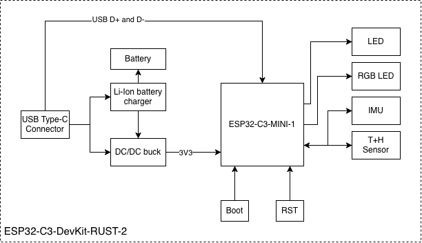
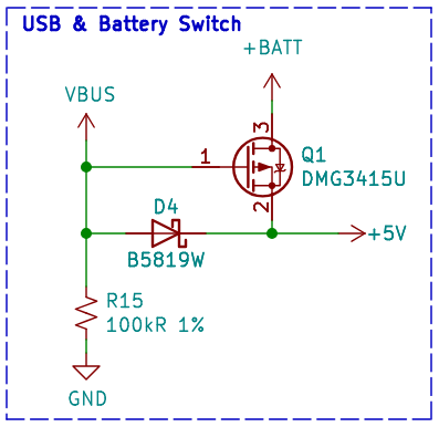
There are three mutually exclusive ways to provide power to the board:

  • USB type-C port, default power supply

  • 5V and GND pin headers

  • BAT and GND pin headers (for single-cell lithium battery)

It is recommended to use the first option: USB type-C port.

Note

The board operates at a 5 V power supply and requires a minimum current of 0.5 A. If your application demands a current exceeding 0.5 A, consider connecting the board via a powered USB hub to ensure stable operation.

Header Block

The two tables below provide the Name and Function of the pin headers on both sides of the board (left and right). The pin header names are shown in ESP32-C3-DevKit-RUST-2 (with the ESP32-C3-MINI-1 module) - front. The numbering is the same as in the ESP32-C3-DevKit-RUST-2 Schematic (PDF).

Left Header

No.

Name

Type 1

Function

1

RST

I

EN / CHIP_PU

2

3V3

P

3.3 V power supply

3

N/C

Not connected

4

GND

G

Ground

5

IO0

I/O/T

GPIO0, ADC1_CH0

6

IO1

I/O/T

GPIO1, ADC1_CH1

7

IO2

I/O/T

GPIO2 2, ADC1_CH2

8

IO3

I/O/T

GPIO3, ADC1_CH3

9

IO4

I/O/T

GPIO4, ADC2_CH0

10

IO5

I/O/T

GPIO5, ADC2_CH1

11

IO6

I/O/T

GPIO6, MTCK

12

IO7

I/O/T

GPIO7, MTDO, LED

13

IO8

I/O/T

GPIO8 2, LOG

14

RX

I/O/T

GPIO21, U0RXD

15

TX

I/O/T

GPIO20, U0TXD

16

IO9

I/O/T

GPIO9 2, BOOT

Right Header

No.

Name

Type 1

Function

1

BAT+

P

Battery supply

2

EN

I

Enable

3

5V

P

USB VBUS

4

N/C

Not connected

5

N/C

Not connected

6

N/C

Not connected

7

N/C

Not connected

8

N/C

Not connected

9

IO18

I/O/T

GPIO18, USB_D-

10

IO19

I/O/T

GPIO19, USB_D+

11

N/C

Not connected

12

N/C

Not connected

1(1,2)

P: Power supply; I: Input; O: Output; T: High impedance.

2(1,2,3)

GPIO2, GPIO8, and GPIO9 are strapping pins of the ESP32-C3 chip. These pins are used to control several chip functions depending on binary voltage values applied to the pins during chip power-up or system reset. For description and application of the strapping pins, please refer to Section Boot Configurations in ESP32-C3 Datasheet.

I2C Peripherals

Peripheral

Part number

Address

IMU

ICM-42670-P

0x68

Temperature and Humidity

SHTC3

0x70

Sensors

Sensors on I2C bus (click to enlarge)

Sensors on I2C bus (click to enlarge)

I2C Signal Mapping

Signal

GPIO

SDA

GPIO10

SCL

GPIO8

Peripherals Connected to GPIOs

I/O Device

GPIO

WS2812 LED

GPIO2

LED

GPIO7

Button/Boot

GPIO9

Buttons

Buttons Circuit (click to enlarge)

Buttons Circuit (click to enlarge)

Power Supply

Power Supply Circuit (click to enlarge)

Power Supply Circuit (click to enlarge)

Power Supply from USB

Power Switch Circuit (click to enlarge)

Power Switch Circuit (click to enlarge)

Lithium Battery Charging

Lithium Battery charging circuit (click to enlarge)

Lithium Battery charging circuit (click to enlarge)

Pin Layout

ESP32-C3-DevKit-RUST-2 (with the ESP32-C3-MINI-1 module, click to enlarge)

ESP32-C3-DevKit-RUST-2 Pin Layout (with the ESP32-C3-MINI-1 module, click to enlarge)

Hardware Revision Details

This is a new version with minor changes from the previous ESP32-C3-DevKit-RUST-1 board. The list of changes are as follows:

  • Changed the GPIO for the user LED from GPIO7 to GPIO10.

  • Changed the pin header hole diameter from 0.8 mm to 1.0 mm.

  • Fixed issues on the silkscreen layer.

  • Changes on the traces on the I2C bus for better signal integrity.