ESP-SensairShuttle v1.0
Note
Please check the silkscreen version number on the mainboard (in the white circle at the top right corner of the front or back of the mainboard) to confirm your development board version. For v1.0 development boards, please refer to this user guide.
This guide will help you get started with ESP-SensairShuttle quickly and provide detailed information about this development board.
ESP-SensairShuttle is a development board jointly launched by Espressif and Bosch Sensortec for motion sensing and large language model human-computer interaction scenarios, dedicated to promoting the deep integration of multimodal sensing and intelligent interaction technologies. The platform covers typical application scenarios such as AI toys, smart homes, sports health, and smart offices, supporting a complete technical chain from environmental sensing, behavior understanding to intelligent feedback, providing a more natural, real-time, and intelligent interaction experience for next-generation intelligent terminals.
ESP-SensairShuttle uses Espressif’s ESP32-C5-WROOM-1-N16R8 module as the main controller, featuring dual-band Wi-Fi 6 (802.11ax) at 2.4 & 5 GHz, Bluetooth® 5 (LE), Zigbee, and Thread (802.15.4) wireless communication capabilities. In addition, the mainboard provides rich peripheral interfaces, including Bosch Sensortec Shuttle Board (only supports shuttle board 3.0 version) interface, microphone and speaker interfaces, and battery power interface. Users can flexibly achieve multi-dimensional sensing such as air quality, gesture actions, attitude direction, and magnetic field information by replacing different Shuttle sensor daughterboards (Espressif officially supports BME690 and BMI270 & BMM350 daughterboards), suitable for teaching demonstrations, algorithm verification, and multi-scenario prototype development.
In terms of audio, ESP-SensairShuttle supports external microphones and speakers, which can seamlessly connect to various large language models to achieve natural and smooth AI voice interaction capabilities, suitable for voice interaction products that require large model empowerment such as AI toys, smart speakers, and smart control panels.
This guide includes the following content:
Getting Started: Briefly introduces the development board and hardware and software setup guides.
Hardware Reference: Details the hardware of the development board.
Hardware Revision History: Introduces hardware revision history and known issues (if any).
Related Documents: Lists links to related documents.
Note
For instructions on using the factory firmware, please refer to ESP-SensairShuttle User Guide.
Getting Started
This section will briefly introduce ESP-SensairShuttle and explain how to flash firmware on ESP-SensairShuttle and related preparation work.
Component Overview
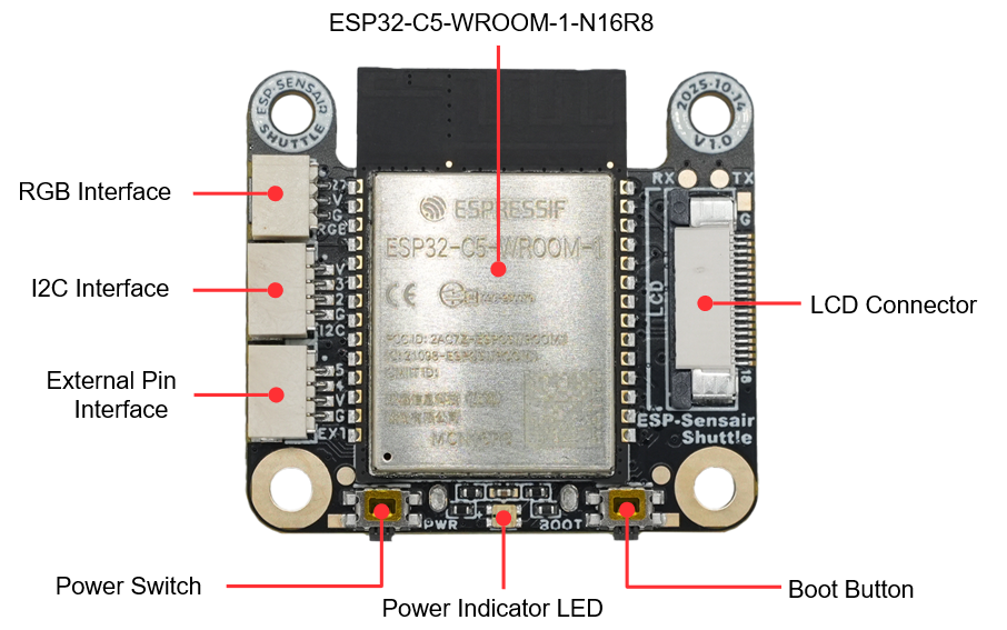
SensairShuttle-Mainboard PCB Front View (Click to enlarge)
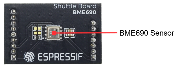
ShuttleBoard-BME690 PCB Front View (Click to enlarge)
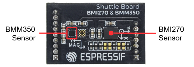
ShuttleBoard-BMI270&BMM350 PCB Front View (Click to enlarge)

ESP-SensairShuttle LCD Screen Photo (Click to enlarge)
The main components on the front PCB are introduced in clockwise order below.
Main Component |
Description |
|---|---|
MainBoard |
|
External Pin Interface |
4-pin external pin interface, from top to bottom: GPIO5, GPIO4, VDD, GND. Note: GPIO5 is not available by default. To use it, please install the R14 resistor. |
I2C Interface (External I2C Interface) |
4-pin external I2C interface that can connect to devices supporting I2C protocol communication. |
RGB Interface (External RGB Strip Interface) |
3-pin external RGB strip interface that can connect to WS2812 and other RGB strips. |
ESP32-C5-WROOM-1-N16R8 |
Main control module, integrated with 16 MB Flash and 8 MB PSRAM, featuring dual-band Wi-Fi 6 (802.11ax) at 2.4 & 5 GHz, Bluetooth® 5 (LE), Zigbee, and Thread (802.15.4) wireless communication capabilities. |
LCD Connector |
Used to connect LCD screen with a resolution of 240(H) x 284(V). |
Boot Button |
Used to manually enter download mode, can also be used as a regular function button. |
Power Indicator LED |
Used to indicate device power status. For indicator status details, please refer to the Power Options section. |
Power Switch |
Used to control device power on/off. Click the power switch to toggle the power state. |
ShuttleBoard-BME690 |
|
BME690 Sensor |
Bosch BME690 gas sensor that can detect air quality, including temperature, humidity, pressure, and gas resistance, supporting I2C and SPI protocol communication. |
ShuttleBoard-BMI270&BMM350 |
|
BMI270 Sensor |
Bosch BMI270 inertial measurement unit that can detect three-axis acceleration and three-axis angular velocity, supporting I2C and SPI protocol communication. |
BMM350 Sensor |
Bosch BMM350 magnetometer that can detect three-axis magnetic field strength, supporting I2C protocol communication. |
LCD Screen |
Matching LCD screen, model ST7789P3, size 1.83 inches, resolution 240(H) x 284(V), using 4-line SPI interface communication. The screen is connected to the mainboard through the LCD connector, and supports power control via GPIO5 (PWR_CTRL). |
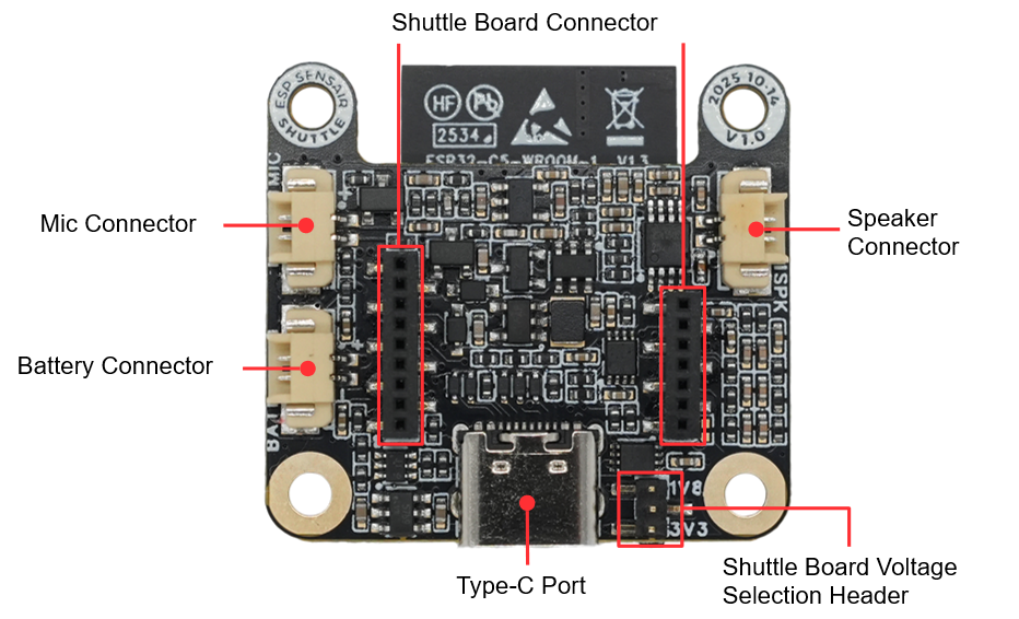
SensairShuttle-Mainboard PCB Back View (Click to enlarge)
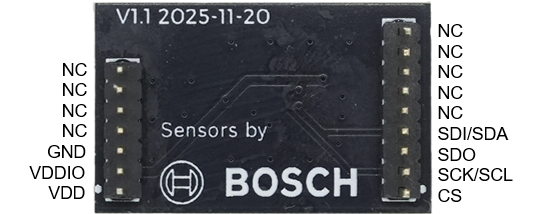
ShuttleBoard-BME690 PCB Back View (Click to enlarge)
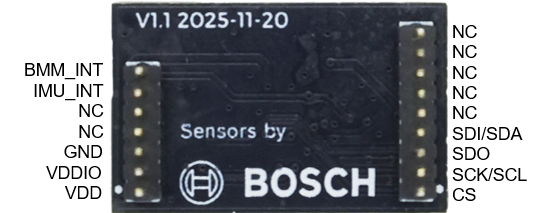
ShuttleBoard-BMI270&BMM350 PCB Back View (Click to enlarge)
The main components on the back PCB are introduced in clockwise order below.
Main Component |
Description |
|---|---|
MainBoard |
|
Battery Connector |
Battery connector that can connect to an external 3.7V lithium battery, using HC-1.25-2P wire-to-board connector. |
Mic Connector |
2-wire microphone connector that can connect to an external analog microphone, using HC-1.25-2P wire-to-board connector. |
Shuttle Board Connector |
9+7 pin 1.27mm female header connector that can connect to ShuttleBoard-BME690, ShuttleBoard-BMI270&BMM350 and other sensor daughterboards. |
Speaker Connector |
2-wire speaker connector that can connect to an external speaker, using HC-1.25-2P wire-to-board connector. |
Type-C Port (USB-C Interface) |
USB-C interface for power supply, program flashing, and debugging, supporting lithium battery charging. |
ShuttleBoard-BME690 |
Pin definitions for the sensor daughterboard are marked in the figure. |
ShuttleBoard-BMI270&BMM350 |
Pin definitions for the sensor daughterboard are marked in the figure. |
Application Examples
The following are application examples for the development board:
ESP-SensairShuttle Factory Demo - A full-featured demo system based on the ESP-Brookesia framework, showcasing an app-based UI management system and multiple demo applications (e.g., compass, temperature & air quality monitoring, gesture recognition).
For more examples and the latest updates, please refer to the examples folder.
To try the examples or develop custom applications, please follow the steps in the Start Development section.
Start Development
Before powering on, please ensure that ESP-SensairShuttle is intact.
Required Hardware
ESP-SensairShuttle mainboard, ShuttleBoard-BME690 daughterboard, ShuttleBoard-BMI270&BMM350 daughterboard, LCD screen
USB cable
Computer (Windows, Linux, or macOS)
Note
Please ensure you use an appropriate USB cable. Some cables can only be used for charging and cannot be used for data transmission and programming.
Hardware Setup
LCD Screen Cable Installation
Before starting to use the development board, please follow the steps below to install the LCD screen cable:
Confirm Cable Orientation: Place the LCD screen cable with the gold fingers facing up, ensuring the cable orientation is correct (the pin number [18] on the screen cable should correspond to the pin number [18] on the PCB).
Insert Cable: First, release the black lock of the LCD connector, then insert the screen cable into the LCD connector on the mainboard. When inserting, ensure the screen cable is aligned with the connector. You can use tweezers to assist if it is inconvenient to install by hand.
Lock Connector: Lock the black lock of the LCD connector to ensure the screen cable is securely connected.
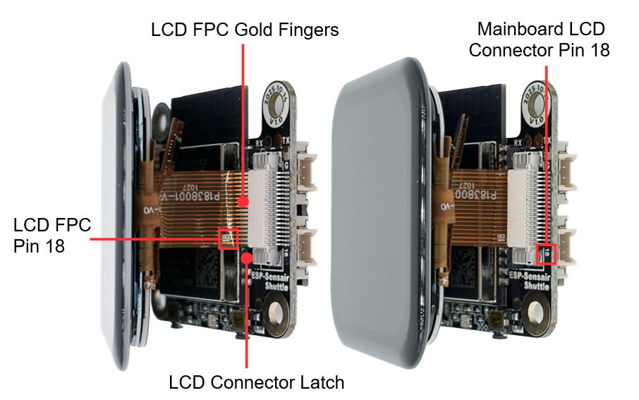
LCD Screen Cable Installation Diagram (Click to enlarge)
Warning
Do not use excessive force when installing the cable to avoid damaging the cable or connector.
Ensure the cable orientation is correct. An incorrect orientation will cause the screen not to light up.
If you need to remove the cable, first unlock the connector, then gently pull it out. Avoid directly pulling the cable.
USB Connection
Connect ESP-SensairShuttle to your computer using a USB cable, and flash firmware, debug, and power supply through the Type-C (USB-C Interface).
Software Setup
Please visit the ESP-IDF Getting Started section to learn how to quickly set up the development environment and flash applications to your development board.
Note
The development board uses a USB port to communicate with the computer. Most operating systems (Windows, Linux, macOS) have the required drivers pre-installed, and the development board can be automatically recognized after insertion. If the device cannot be recognized or a serial connection cannot be established, please refer to Establish Serial Connection for detailed steps on installing drivers.
Hardware Reference
Function Block Diagram
The main components and connection methods of ESP-SensairShuttle are shown in the figure below.
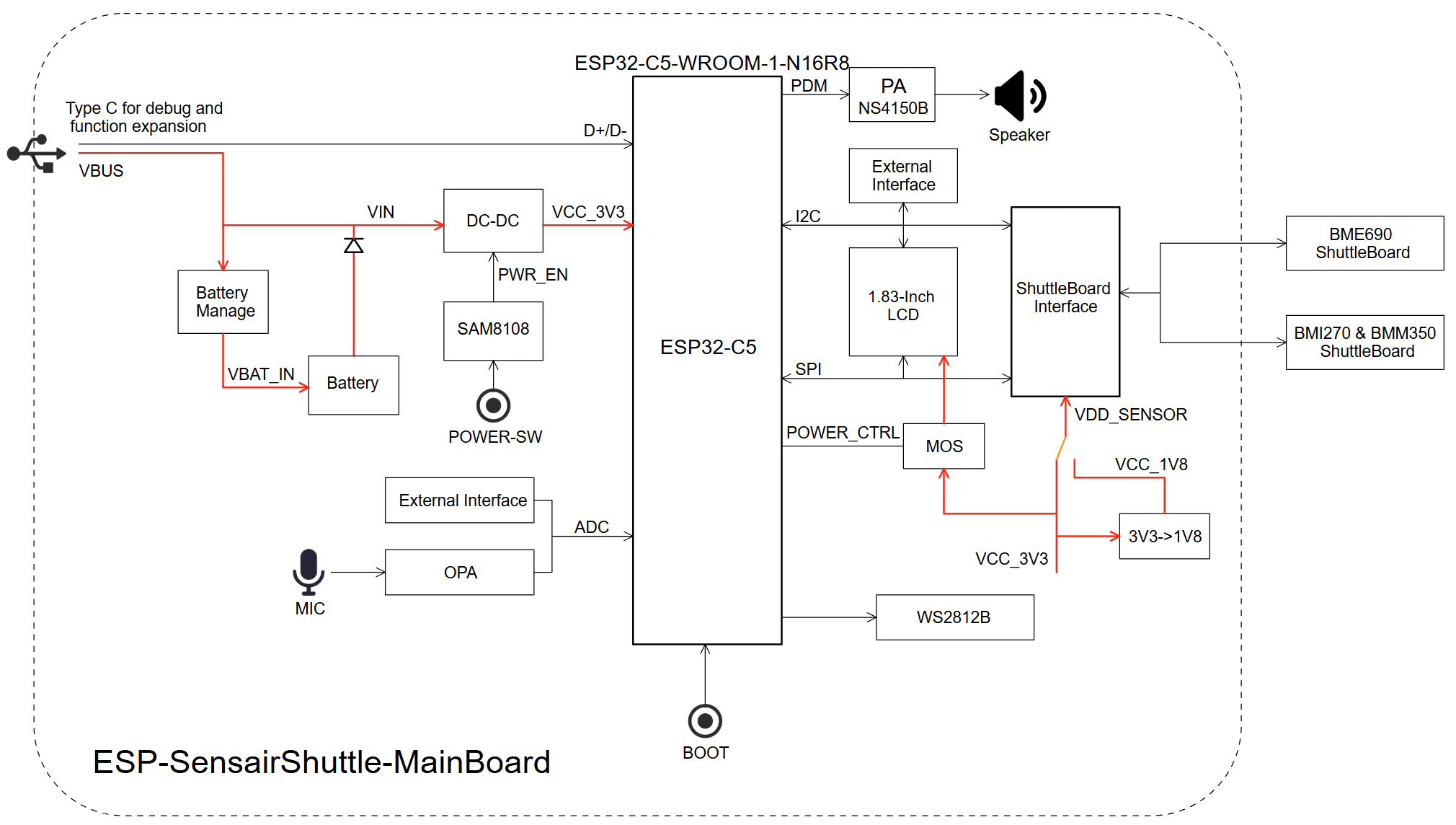
ESP-SensairShuttle Function Block Diagram (Click to enlarge)
Power Options
The development board can be powered by the following methods:
Power via
Type-C (USB-C Interface)When using this method, connect the Type-C interface on the device using a USB Type-C cable. If no lithium battery is installed, the power indicator LED will be green. If a lithium battery is installed, press the
POWERbutton to turn on the device. At this time, the power indicator LED will be yellow (battery is charging) or green (battery is fully charged).Power via
BatteryThe device can connect to an external 3.7V lithium battery. Press the
POWERbutton to power the device. The power indicator LED will be green when the device is on, and off when the device is off.
Type-C Interface
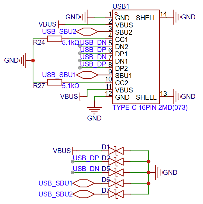
Type-C Interface Circuit Diagram (Click to enlarge)
LCD Interface
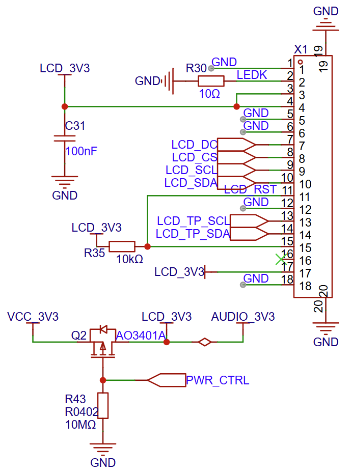
LCD Interface Circuit Diagram (Click to enlarge)
The X1 interface is the LCD screen interface in use. The matching LCD screen specifications for this development board are as follows:
Screen Size: 1.83 inches
Resolution: 240(H) x 284(V)
Driver Chip: ST7789P3
Communication Interface: 4-line SPI Interface
Power Control: Supports controlling screen power on/off via
PWR_CTRL(GPIO5)
For more detailed information, please refer to the Display Specification.
Power Switch Circuit
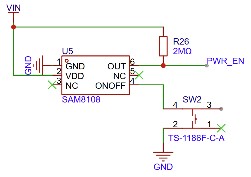
Power Switch Circuit Diagram (Click to enlarge)
Battery Charging Circuit
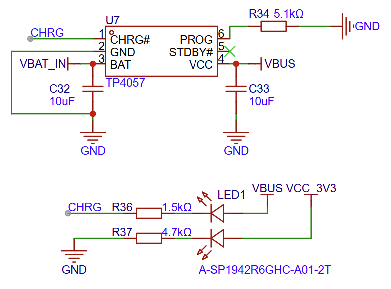
Battery Charging Circuit Diagram (Click to enlarge)
Shuttle Board Interface Circuit
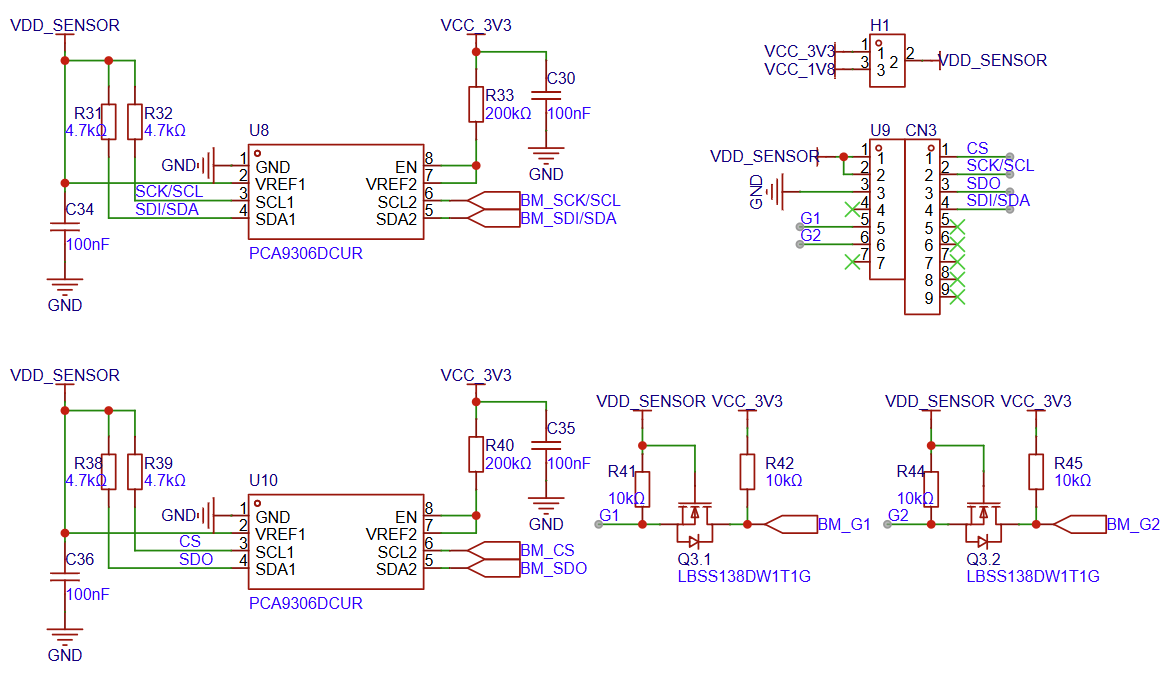
Shuttle Board Interface Circuit Diagram (Click to enlarge)
I2C/RGB/External Pin Interface
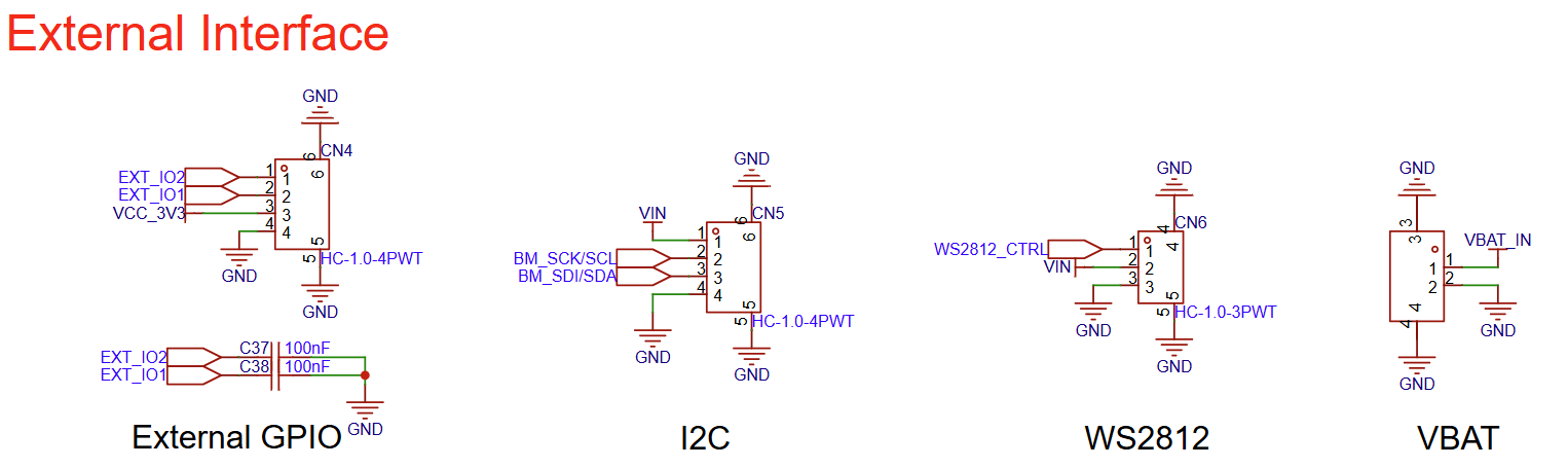
I2C/RGB/External Pin Interface Circuit Diagram (Click to enlarge)
Hardware Revision History
No revision history.