Reference Documentation
Introduction to Functions
The Working Mode of USB Bridge
ESP-Prog-2 establishes a bridge between a computer and a target chip based on ESP32-S3. It can emulate a USB composite device to enable serial data transmission between the computer and the target chip through USB-to-UART bridging, or enable bidirectional JTAG communication between the computer and the target chip through JTAG bridging.
Communication Interface
Program Interface
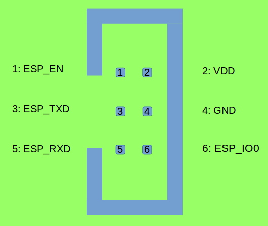
Program Interface (click to enlarge)
JTAG Interface
The design for the JTAG interface on the user board should follow the reference provided in the figure below.

JTAG Interface (click to enlarge)
Fool-proof Design
The ESP-Prog-2 interfaces use boxed header connectors (DC3-6P/DC3-10P) with reverse polarity protection. It is recommended to use connectors of the same type, such as
FTSH-105-01-S-DV-*orDC3-*P.Note
Since the ribbon cables have a fixed orientation, each ESP-Prog-2 interface corresponds to a specific cable connection. Using mismatched cables may result in incorrect wiring. Therefore, please use the official ribbon cables.
LED Status Indication
When the system 3.3 V power supply is on, the red LED lights up.
When ESP-Prog-2 bridges through USB-to-UART, the green LED lights up.
When ESP-Prog-2 bridges through JTAG, the blue LED lights up.
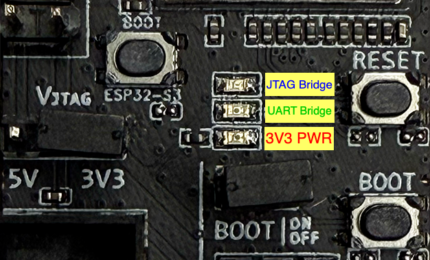
LED Status (click to enlarge)
Pin Headers
- Pin Header to Select Power Supply
The labeled pins are the power input pins for each interface. When connected to 5 V, the power output of the interface is 5 V; when connected to 3.3 V, the power output of the interface is 3.3 V.
- BOOT On/Off Pin
The boot mode selection pin can be used as a normal GPIO after the chip is powered on. In order to prevent ESP-Prog-2 from affecting the normal use of the BOOT pin on your board, you can manually control the BOOT signal.
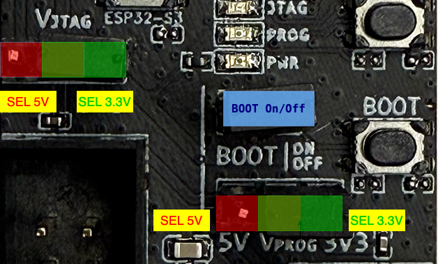
Pin Headers (click to enlarge)
For further design documentation for the board, please contact sales: sales@espressif.com.