ESP32-S2-Kaluga-1 Kit v1.3
Older version: ESP32-S2-Kaluga-1 Kit v1.2
The ESP32-S2-Kaluga-1 kit v1.3 is a development kit by Espressif that is mainly created to:
Demonstrate the ESP32-S2’s human-computer interaction functionalities
Provide the users with the tools for development of human-computer interaction applications based on the ESP32-S2
There are many ways of how the ESP32-S2’s abundant functionalities can be used. For starters, the possible use cases may include:
Smart home: From simplest smart lighting, smart door locks, smart sockets, to video streaming devices, security cameras, OTT devices, and home appliances
Battery-powered equipment: Wi-Fi mesh sensor networks, Wi-Fi-networked toys, wearable devices, health management equipment
Industrial automation equipment: Wireless control and robot technology, intelligent lighting, HVAC control equipment, etc.
Retail and catering industry: POS machines and service robots
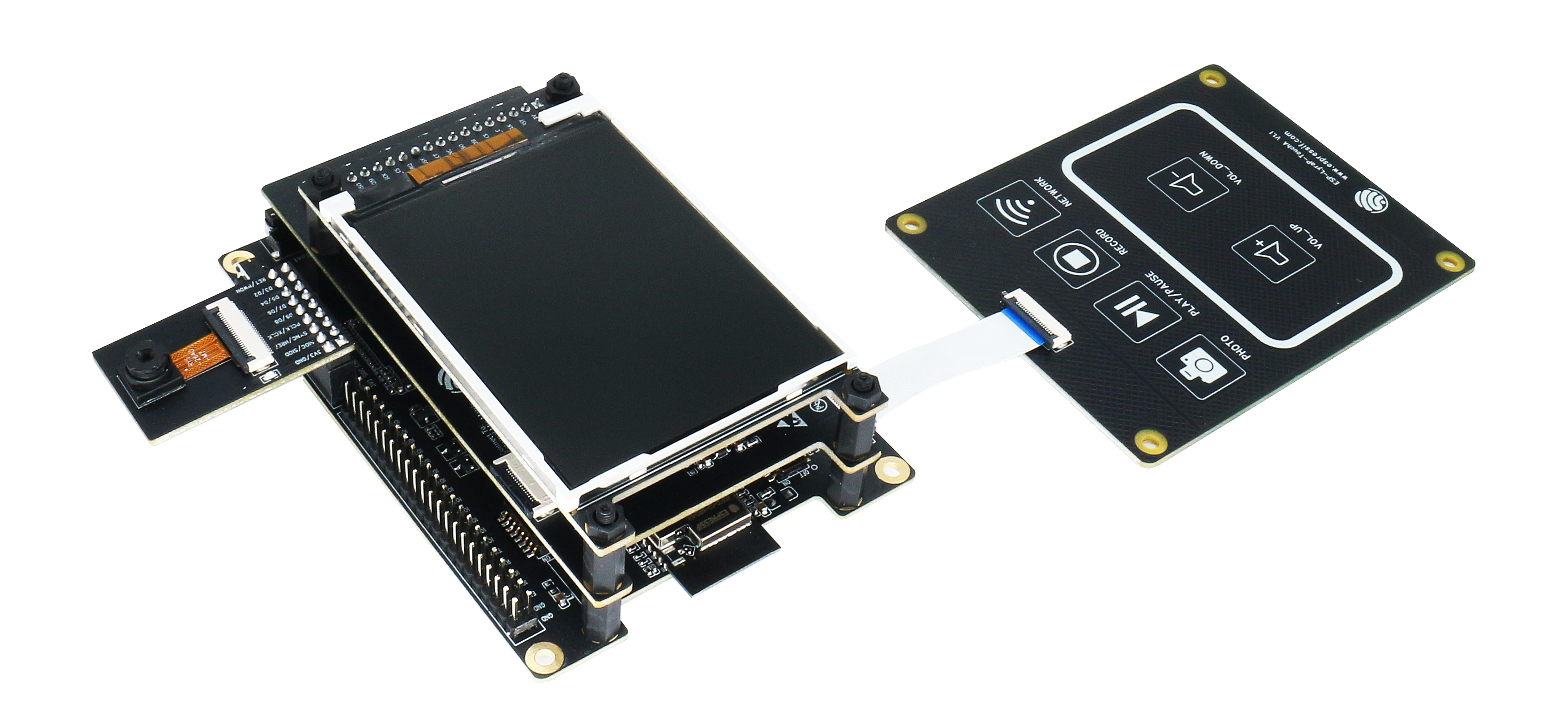
ESP32-S2-Kaluga-1-Kit Overview (click to enlarge)
The ESP32-S2-Kaluga-1 kit consists of the following boards:
Main board: ESP32-S2-Kaluga-1
Extension boards:
ESP-LyraT-8311A v1.3 - audio player
ESP-LyraP-TouchA v1.1 - touch panel
ESP-LyraP-LCD32 v1.2 - 3.2” LCD screen
ESP-LyraP-CAM v1.1 - camera board
Due to the presence of multiplexed pins on ESP32-S2, certain extension board combinations have limited compatibility. For more details, please see Compatibility of Extension Boards.
This document is mostly dedicated to the main board and its interaction with the extension boards. For more detailed information on each extension board, click their respective links.
This guide covers:
Getting Started: Provides an overview of the ESP32-S2-Kaluga-1 and hardware/software setup instructions to get started.
Hardware reference: Provides more detailed information about the ESP32-S2-Kaluga-1’s hardware.
Hardware Revision Details: Covers revision history, known issues, and links to user guides for previous versions of the ESP32-S2-Kaluga-1.
Related Documents: Gives links to related documentation.
Getting Started
This section describes how to get started with the ESP32-S2-Kaluga-1. It begins with a few introductory sections about the ESP32-S2-Kaluga-1, then Section Start Application Development provides instructions on how to do the initial hardware setup and then how to flash firmware onto the ESP32-S2-Kaluga-1.
Overview
The ESP32-S2-Kaluga-1 main board is the heart of the kit. It integrates the ESP32-S2-WROVER module and all the connectors for extension boards. This board is the key tool in prototyping human-computer interaction interfaces.
The ESP32-S2-Kaluga-1 board has connectors for boards with:
Extension header (ESP-LyraT-8311A, ESP-LyraP-LCD32)
Camera header (ESP-LyraP-CAM)
Touch FPC coneector (ESP-LyraP-TouchA)
LCD FPC connector (no official extension boards yet)
I2C FPC connector (no official extension boards yet)
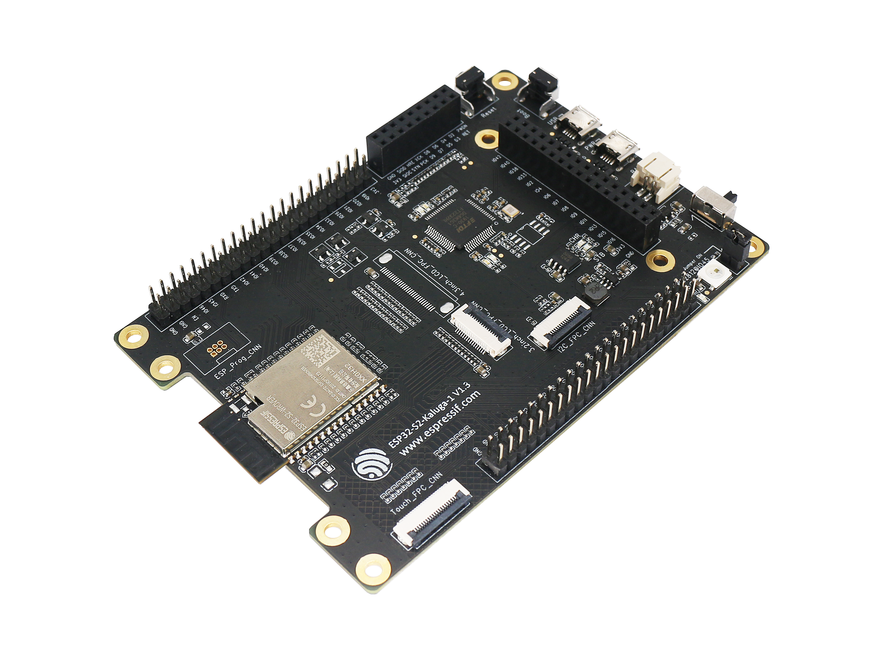
ESP32-S2-Kaluga-1 (click to enlarge)
All the four extension boards are specially desgined to support the following features:
- Touch panel control
Six touch buttons
Supports acrylic panels up to 5 mm
Wet hand operation
Water rejection, ESP32-S2 can be configured to disable all touchpads automatically if multiple pads are simultaneously covered with water and to re-enable touchpads if the water is removed
- Audio playback
Connect speakers to play audio
Use together with the Touch panel to control audio playback and adjust volume
- LCD display
LCD interface (8-bit parallel RGB, 8080, and 6800 interface)
- Camera image acquisition
Supports OV2640 and OV3660 camera modules
8-bit DVP image sensor interface (ESP32-S2 also supports 16-bit DVP image sensors, you can design it yourself)
Clock frequency up to 40 MHz
Optimized DMA transmission bandwidth for easier transmission of high-resolution images
Description of Components
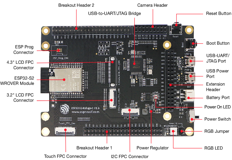
ESP32-S2-Kaluga-1 - front (click to enlarge)
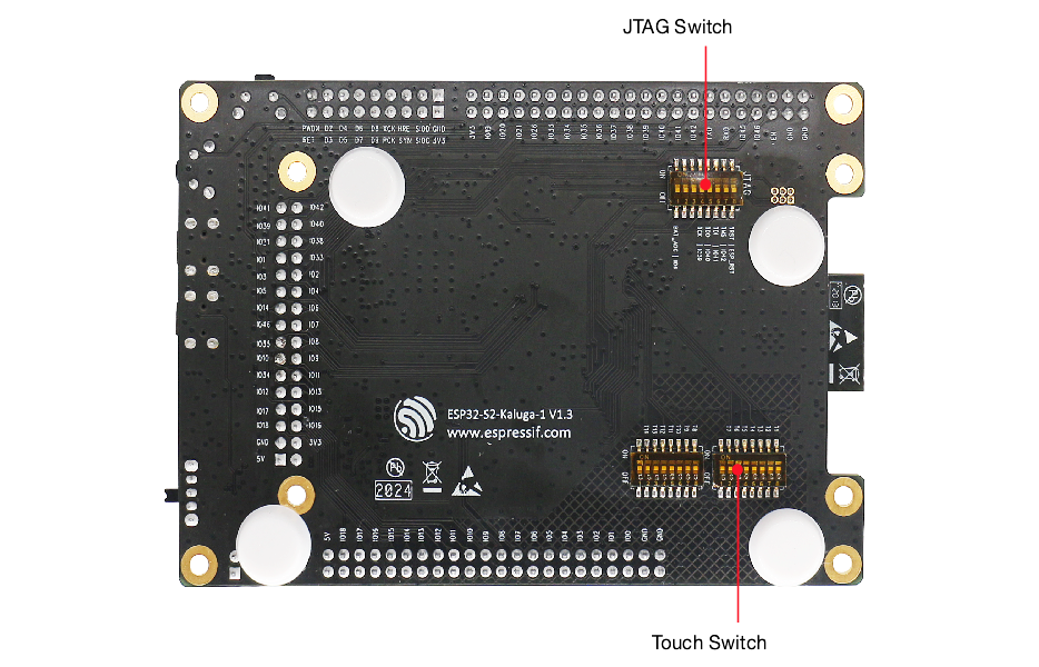
ESP32-S2-Kaluga-1 - back (click to enlarge)
The description of components starts from the ESP32-S2 module on the left side and then goes clockwise.
Reserved means that the functionality is available, but the current version of the kit does not use it.
Key Component |
Description |
|---|---|
ESP32-S2-WROVER Module |
Module integrating the ESP32-S2 chip that provides Wi-Fi connectivity, data processing power, and flexible data storage. |
4.3” LCD FPC Connector |
(Reserved) Connect to a 4.3” LCD extension board using the FPC cable. |
ESP Prog Connector |
(Reserved) Connection for Espressif’s download device (ESP-Prog) to flash ESP32-S2 system. |
JTAG Switch |
Switch to ON to enable connection between ESP32-S2 and FT2232; JTAG debugging will then be possible using USB-UART/JTAG Port. See also JTAG Debugging. |
Breakout Header 2 |
Some GPIO pins of the ESP32-S2-WROVER module are broken out to this header, see labels on the board. |
USB-to-UART/JTAG Bridge |
FT2232 adapter board allowing for communication over USB port using UART/JTAG protocols. |
Camera Header |
Mount a camera extension board here (e.g., ESP-LyraP-CAM). |
Extension Header |
Mount the extension boards having such connectors here. |
Reset Button |
Press this button to restart the system |
Boot Button |
Holding down Boot and then pressing Reset initiates Firmware Download mode for downloading firmware through the serial port. |
USB-UART/JTAG Port |
Communication interface (UART or JTAG) between a PC and the ESP32-S2 module. |
USB Power Port |
Power supply for the board. |
Battery Port |
Connect an external battery to the 2-pin battery connector. |
Power On LED |
Turns on when the USB or an external power supply is connected to the board. |
Power Switch |
Switch to ON to power the system. |
RGB Jumper |
To have access to the RGB LED, place a jumper onto the pins. |
RGB LED |
Programmable RGB LED and controlled by GPIO45. Before using it, you need to put RGB Jumper ON. |
Power Regulator |
Regulator converts 5 V to 3.3 V. |
I2C FPC Connector |
(Reserved) Connect to other I2C extension boards using the FPC cable. |
Breakout Header 1 |
Some GPIO pins of the ESP32-S2-WROVER module are broken out to this header, see labels on the board. |
Touch FPC Connector |
Connect the ESP-LyraP-TouchA extension board using the FPC cable. |
Touch Switch |
In OFF position, GPIO1 to GPIO14 are used for connection to touch sensors; switch to ON if you want to use them for other purposes. |
3.2” LCD FPC connector |
Connect a 3.2” LCD extension board (e.g., ESP-LyraP-LCD32) using the FPC cable. |
Start Application Development
Before powering up your ESP32-S2-Kaluga-1, please make sure that it is in good condition with no obvious signs of damage.
Required Hardware
ESP32-S2-Kaluga-1
Two USB 2.0 cables (Standard-A to Micro-B)
For power supply
For UART/JTAG communication
Computer running Windows, Linux, or macOS
Any extension boards of your choice
Hardware Setup
Connect the extension board(s) of your choice (go to their respective user guides if necessary)
Plug in both USB cables
Turn the Power Switch to ON - the Power On LED will light up
Software Setup
Please proceed to Get Started, where Section Installation Step by Step will quickly help you set up the development environment.
The programming guide and application examples for your ESP32-S2-Kaluga-1 kit can be found in esp-dev-kits repository on GitHub.
Contents and Packaging
Retail orders
If you order one or several samples of the kit, each ESP32-S2-Kaluga-1 development kit comes in an individual package.
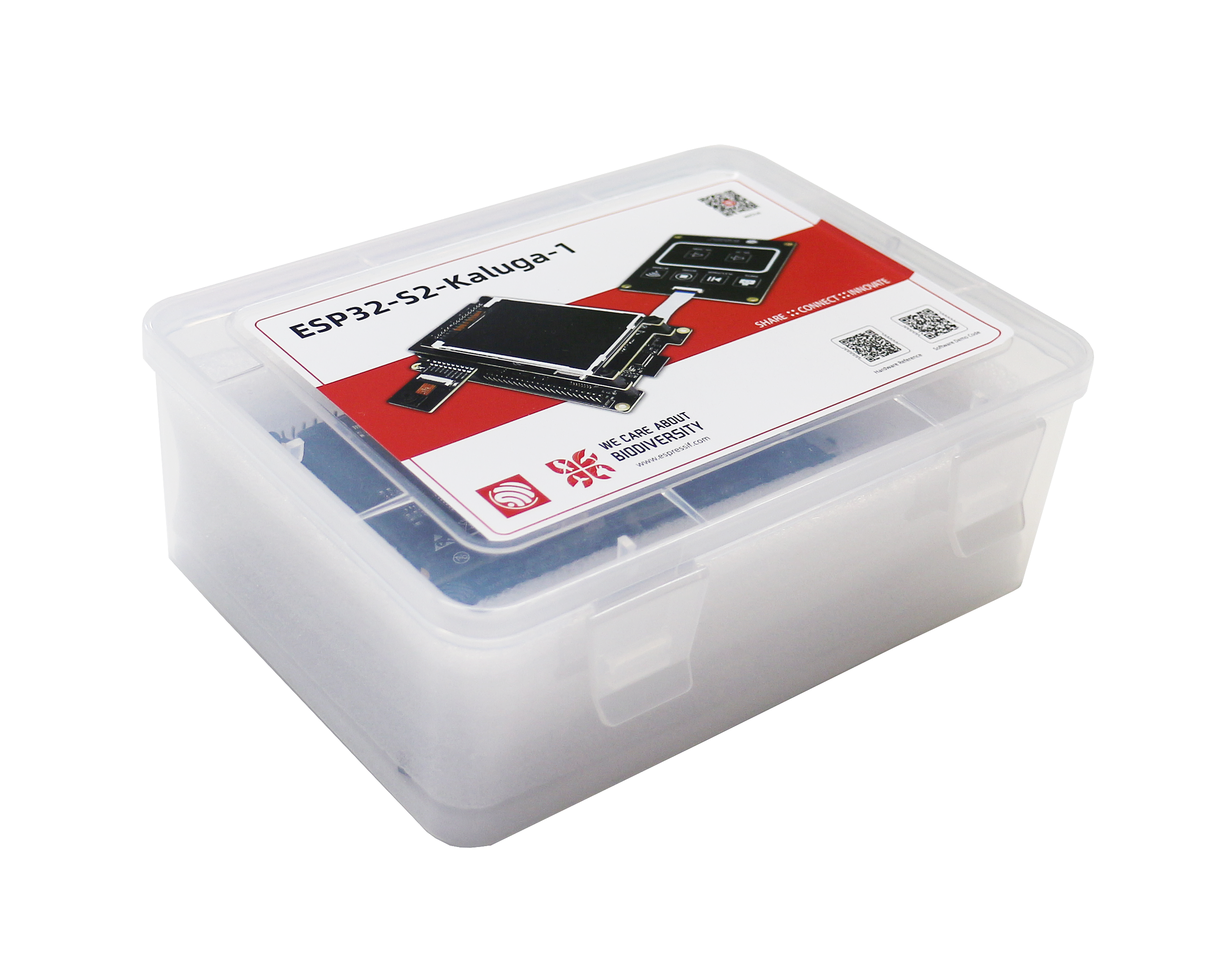
ESP32-S2-Kaluga-1 - package
The contents are as follows:
- Main Board
ESP32-S2-Kaluga-1
- Extension Boards:
ESP-LyraT-8311A
ESP-LyraP-CAM
ESP-LyraP-TouchA
ESP-LyraP-LCD32
- Connectors
20-pin FPC cable (to connect ESP32-S2-Kaluga-1 to ESP-LyraP-TouchA)
- Fasteners
Mounting bolts (x8)
Screws (x4)
Nuts (x4)
For retail orders, please go to https://www.espressif.com/en/company/contact/buy-a-sample.
Wholesale Orders
If you order in bulk, the boards come in large cardboard boxes.
For wholesale orders, please go to https://www.espressif.com/en/contact-us/sales-questions.
Hardware Reference
Block Diagram
A block diagram below shows the components of the ESP32-S2-Kaluga-1 and their interconnections.
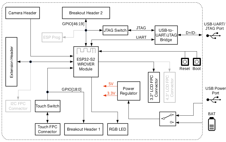
ESP32-S2-Kaluga-1 block diagram
Power Supply Options
There are four ways to provide power to the board:
Micro USB port, default power supply
External battery via the 2-pin battery connector
5V and GND header pins
3V3 and GND header pins
Compatibility of Extension Boards
If you want to use more than one extension board at the same time, please check the table given below.
Boards Used |
HW Conflict |
Limitations |
Solution |
|---|---|---|---|
8311A v1.3 + CAM v1.1 |
I2S Controller |
ESP32-S2 has only one I2S interface. But both extension boards require connection via the ESP32-S2’s I2S interface (LyraT-8311A in Standard mode, ESP-LyraP-CAM in Camera mode). |
Utilize time division multiple access, or use a different audio module that can be connected via other GPIOs or DAC. |
TouchA v1.1 + LCD32 v1.2 |
IO11, IO6 |
Touch actions cannot be triggered because of the multiplexed pin IO11. ESP-LyraP-LCD32 will not be affected because its BLCT pin will be disconnected fron IO6. |
Do not initialize IO11 (NETWORK) for your ESP-LyraP-TouchA, or configure the BLCT pin to -1 (= do not use BLCT) for your ESP-LyraP-LCD32. |
8311A v1.3 + LCD32 v1.2 |
IO6 |
BLCT pin of ESP32-S2-Kaluga-1 will be disconnected from IO6. |
Configure the BK pin to -1 (= do not use BLCT) for your ESP-LyraP-LCD32. |
TouchA v1.1 + 8311A v1.3 |
Pin BT_ADC on ESP-LyraT-8311A |
This pin is required for initialization of the six button on ESP-LyraT-8311A. At the same time, ESP-LyraP-TouchA needs this pin for its touch actions. |
If you plan to use buttons on ESP-LyraT-8311A, do not initialize pin IO6 (PHOTO) for your ESP-LyraP-TouchA. |
TouchA v1.1 + CAM v1.1 |
IO1, IO2, IO3 |
Cannot be used simultaneously because of the mentioned multiplexed pins. |
For ESP-LyraP-TouchA, do not initialize IO1 (VOL_UP), IO2 (PLAY), and IO3 (VOL_DOWN). |
TouchA v1.1 + LCD32 v1.2 + CAM v1.1 |
IO1, IO2, IO3, IO11 |
Conflicts on the mentioned multiplexed pins. |
For ESP-LyraP-TouchA, do not initialize IO1 (VOL_UP), IO2 (PLAY), IO3 (VOL_DOWN), and IO11 (NETWORK). |
TouchA v1.1 + LCD32 v1.2 + 8311A v1.3 |
IO6, IO11 |
If ESP-LyraT-8311A’s pin BT_ADC is used to initialize the board’s six buttons, IO6 and IO11 will not be available for the other boards. |
Do not initialize IO11 (NETWORK) for your ESP-LyraP-TouchA. Also, if you need to use BT_ADC, do not initialize IO6 (PHOTO). |
Also, all extension boards and the JTAG interface share the same pins IO39, IO40, IO41 and IO42. For this reason, the following may disturb the JTAG operation:
Plugging in any extension board
Debugging an application that is using an extension board
Hardware Revision Details
ESP32-S2-Kaluga-1 Kit v1.3
The following pins re-assigned to fix the download issue
Camera D2: GPIO36
Camera D3: GPIO37
AU_I2S1_SDI: GPIO34
AU_WAKE_INT: GPIO46
RGB pin header moved to the board’s edge
All dip switches moved to the flip side for convenient operation