ESP32 Modules and Boards
Espressif designs and manufactures different modules and development boards to help users evaluate the potential of the ESP32 family of chips.
This document provides description of modules and development boards currently available from Espressif.
Note
For description of previous versions of modules and development boards as well as for description of discontinued ones, please go to Section Previous Versions of ESP32 Modules and Boards.
Modules
This is a family of ESP32-based modules with some integrated key components, including a crystal oscillator and an antenna matching circuit. The modules constitute ready-made solutions for integration into final products. If combined with a few extra components, such as a programming interface, bootstrapping resistors, and pin headers, these modules can also be used for evaluation of ESP32’s functionality.
The key characteristics of these modules are summarized in the table below. Some additional details are covered in the following sections.
Module |
Chip |
Flash, MB |
PSRAM, MB |
Ant. |
Dimensions, mm |
|---|---|---|---|---|---|
ESP32-WROOM-32 |
ESP32-D0WDQ6 |
4 |
– |
MIFA |
18 × 25.5 × 3.1 |
ESP32-WROOM-32D |
ESP32-D0WD |
4, 8, or 16 |
– |
MIFA |
18 × 25.5 × 3.1 |
ESP32-WROOM-32U |
ESP32-D0WD |
4, 8, or 16 |
– |
U.FL |
18 × 19.2 × 3.1 |
ESP32-SOLO-1 |
ESP32-S0WD |
4 |
– |
MIFA |
18 × 25.5 × 3.1 |
ESP32-WROVER (PCB) |
ESP32-D0WDQ6 |
4 |
8 |
MIFA |
18 × 31.4 × 3.3 |
ESP32-WROVER (IPEX) |
ESP32-D0WDQ6 |
4 |
8 |
U.FL |
18 × 31.4 × 3.3 |
ESP32-WROVER-B |
ESP32-D0WD |
4, 8, or 16 |
8 |
MIFA |
18 × 31.4 × 3.3 |
ESP32-WROVER-IB |
ESP32-D0WD |
4, 8, or 16 |
8 |
U.FL |
18 × 31.4 × 3.3 |
ESP32-D.. identifies a dual-core chip, ESP32-S.. identifies a single-core chip
MIFA - Meandered Inverted-F Antenna
U.FL - U.FL / IPEX antenna connector
ESP32-WROOM-32x, ESP32-WROVER-B and ESP32-WROVER-IB modules come with 4 MB flash by default but also available with custom flash sizes of 8 MB and 16 MB, see Espressif Products Ordering Information (PDF)
ESP32 Chip Datasheet (PDF)
Initial release of the ESP32-WROVER module had 4 MB of PSRAM
ESP32-WROOM-32 was previously called ESP-WROOM-32
ESP32-WROOM-32
This is a basic and commonly adopted ESP32 module with the ESP32-D0WDQ6 chip on board. It was the first module of the WROOM / WROVER family released to the market.
For key characteristics, see the table in Section Modules, Espressif Products Ordering Information.
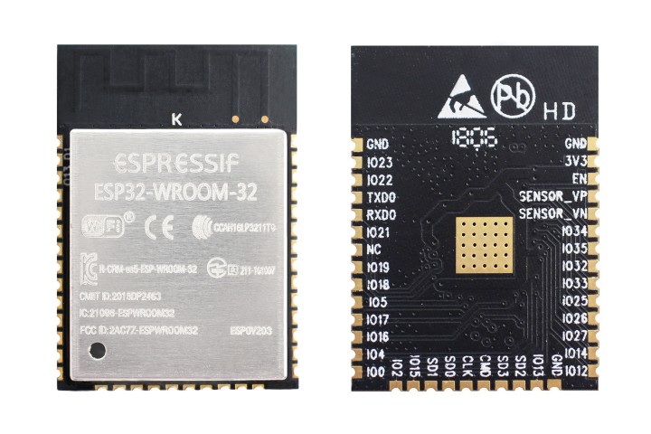
ESP32-WROOM-32 module (front and back)
Documentation
ESP32-WROOM-32 Datasheet (PDF)
ESP32-WROOM-32 Reference Design containing OrCAD schematic, PCB layout, gerber and BOM files
ESP32-WROOM-32D / ESP32-WROOM-32U
Both modules integrate the ESP32-D0WD chip which has a smaller footprint than the chip ESP32-D0WDQ6 installed in ESP32-WROOM-32.
For key characteristics, see the table in Section Modules and Espressif Products Ordering Information.
ESP32-WROOM-32U is the smallest representative of the whole WROOM / WROVER family of modules.
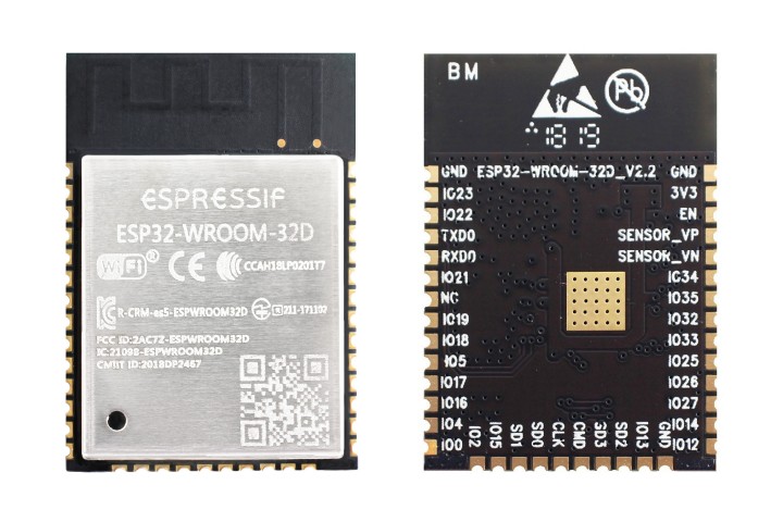
ESP32-WROOM-32D module (front and back)
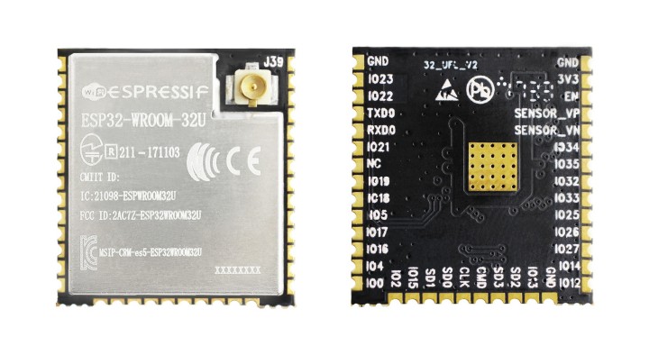
ESP32-WROOM-32U module (front and back)
Documentation
ESP32-SOLO-1
This is a simplified version of the ESP32-WROOM-32D module. It contains a single-core ESP32 chip that supports a clock frequency of up to 160 MHz.
For key characteristics, see the table in Section Modules and Espressif Products Ordering Information.
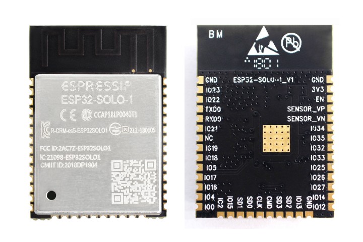
ESP32-SOLO-1 module (front and back)
Documentation
ESP32-SOLO-1 Datasheet (PDF)
ESP32-WROVER series
This series consists of a few modifications of ESP32-WROOM-32x modules, which among other upgrades include additional 8 MB SPI PSRAM (pseudo static RAM).
For details, see the table in Section Modules and Espressif Products Ordering Information.
ESP32-WROVER (PCB) and ESP32-WROVER (IPEX) have PSRAM that operates at 1.8 V and supports up to 144 MHz clock rate.
ESP32-WROVER-B and ESP32-WROVER-IB have PSRAM that operates at 3.3 V and supports up to 133 MHz clock rate.
The picture below shows an ESP32-WROVER module with a PCB antenna.
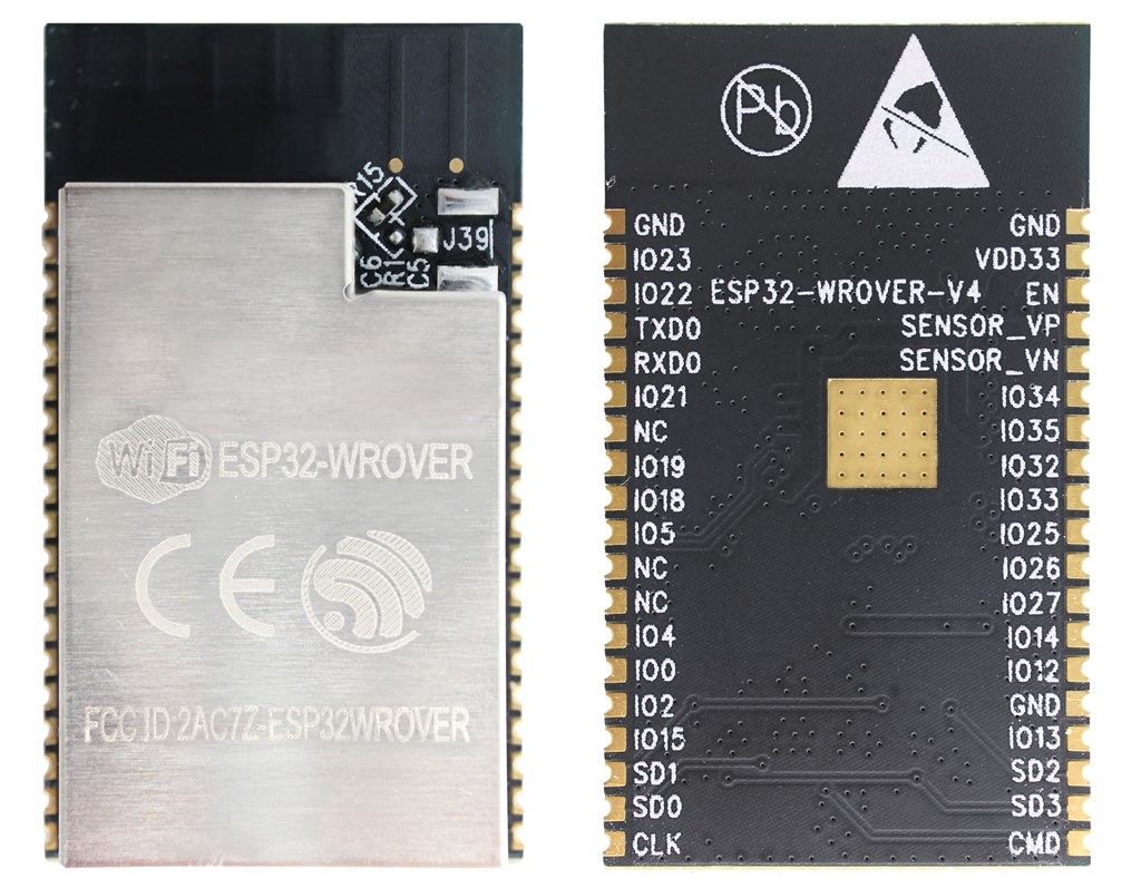
ESP32-WROVER module (front and back)
Documentation
ESP32-WROVER Datasheet (PDF)
ESP32-WROVER-B Datasheet (PDF)
ESP32-WROVER Reference Design containing OrCAD schematic, PCB layout, gerber and BOM files
ESP32-PICO-D4
ESP32-PICO-D4 is a System-in-Package (SiP) module, integrating all peripheral components seamlessly, including the following:
4 MB flash memory
crystal oscillator
filter capacitors
RF matching circuit
For key characteristics, see Espressif Products Ordering Information.
Documentation
ESP32-PICO-D4 Datasheet (PDF)
Development Boards
Depending on the intended functionality, different development boards feature:
Access to different ESP32 GPIO pins.
Different interfaces: USB, JTAG.
Different peripherals: touchpads, LCD screens, SD card slots, female headers for camera modules, etc.
ESP32-PICO-KIT V4.1
This is the smallest available ESP32-based development board. It features all the components for direct connection to a computer’s USB port as well as pin headers for plugging into a mini breadboard.
The board is equipped with the ESP32-PICO-D4 module. With such a module, the creation of a fully functional development board required only a few external components that fit on a PCB as small as 20 x 52 mm. The external components include antenna, LDO, USB-UART bridge, and two buttons for reset and activation of Firmware Download mode.
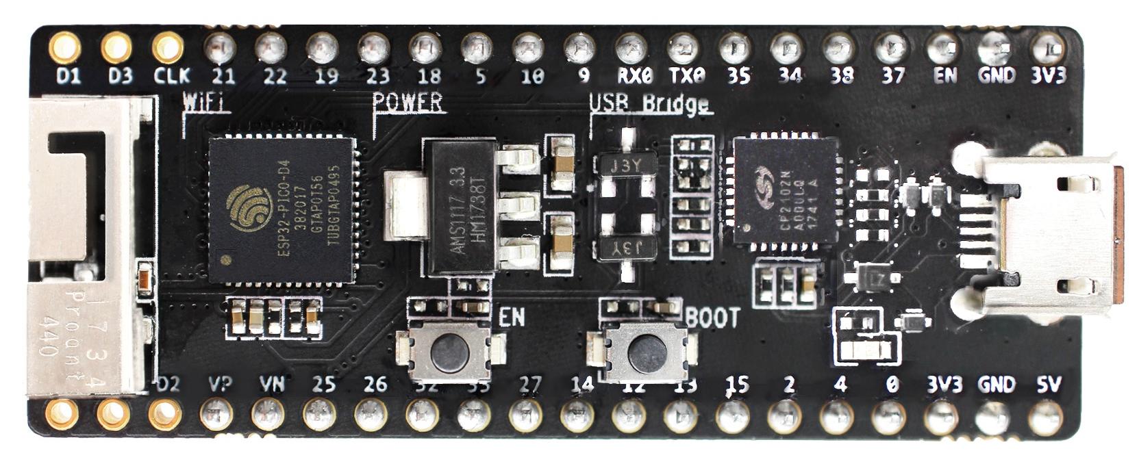
ESP32-PICO-KIT V4.1 board
Comparing to ESP32-PICO-KIT V4, this version features the CP2102N USB-UART bridge that provides faster transfer rates of up to 3 Mbps.
Documentation
ESP32-PICO-KIT Reference Design containing OrCAD schematic, PCB layout, gerber and BOM files
ESP32-PICO-D4 Datasheet (PDF)
Previous Versions
ESP32 DevKitC V4
This is a small and convenient development board that features:
ESP32-WROOM-32 module
USB-to-serial programming interface that also provides power supply for the board
pin headers
pushbuttons for reset and activation of Firmware Download mode
a few other components
Comparing to the previous ESP32 Core Board V2 / ESP32 DevKitC, this version can integrate ESP32-WROVER series module instead of ESP32-WROOM-32 and has the CP2102N chip that supports faster baud rates.
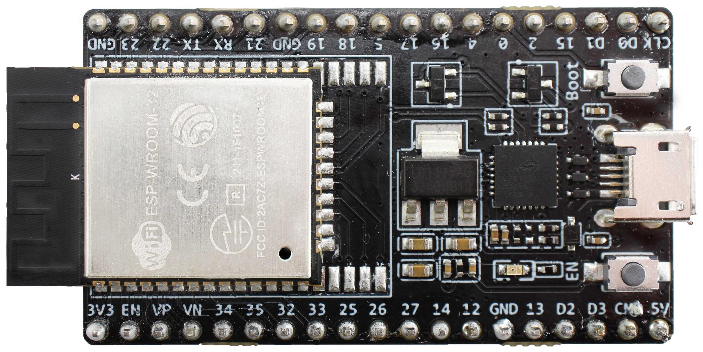
ESP32 DevKitC V4 board
Documentation
ESP32-DevKitC schematic (PDF)
ESP32-DevKitC Reference Design containing OrCAD schematic, PCB layout, gerber and BOM files
Previous Versions
ESP-WROVER-KIT V4.1
This board features:
Dual port USB-to-serial converter for programming
JTAG interface for debugging
MicroSD card slot
3.2” SPI LCD screen
Female headers for a camera module
RGB LED for diagnostics
32.768 kHz XTAL for internal RTC to operate it in low power modes
Power can be supplied either via USB or via a standard 5 mm power supply jack. A power source can be selected with a jumper and can be turned on/off with a separate switch.
This version of the ESP-WROVER-KIT board integrates the ESP-WROVER-B module that has 8 MB PSRAM for flexible extended storage and data processing capabilities. The board can accommodate other versions of ESP modules described in Modules.
Comparing to ESP-WROVER-KIT V3, this board has the following design changes:
JP8, JP11, and JP13 have been combined into a single JP2.
USB connector has been changed to DIP type and moved to the lower right corner of the board.
R61 has been changed to a Zero-ohm resistor.
Some components have been replaced with functional equivalents based on test results and sourcing options, e.g., the EN and Boot buttons.
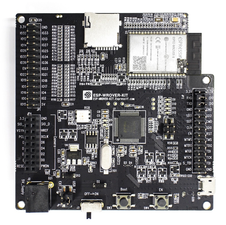
ESP-WROVER-KIT V4.1 board
The board in the picture above integrates the ESP32-WROVER-B module.