Inter-Integrated Circuit (I2C)
Overview
I2C is a serial, synchronous, half-duplex communication protocol that allows co-existence of multiple masters and slaves on the same bus. The I2C bus consists of two lines: serial data line (SDA) and serial clock (SCL). Both lines require pull-up resistors.
With such advantages as simplicity and low manufacturing cost, I2C is mostly used for communication of low-speed peripheral devices over short distances (within one foot).
ESP32 has 2 I2C controller (also referred to as port), responsible for handling communications on the I2C bus. A single I2C controller can operate as master or slave.
Driver Features
I2C driver governs communications of devices over the I2C bus. The driver supports the following features:
Reading and writing bytes in Master mode
Slave mode
Reading and writing to registers which are in turn read/written by the master
Driver Usage
The following sections describe typical steps of configuring and operating the I2C driver:
Configuration - set the initialization parameters (master or slave mode, GPIO pins for SDA and SCL, clock speed, etc.)
Install Driver- activate the driver on one of the two I2C controllers as a master or slave
Depending on whether you configure the driver for a master or slave, choose the appropriate item
Communication as Master - handle communications (master)
Communication as Slave - respond to messages from the master (slave)
Interrupt Handling - configure and service I2C interrupts
Customized Configuration - adjust default I2C communication parameters (timings, bit order, etc.)
Error Handling - how to recognize and handle driver configuration and communication errors
Delete Driver- release resources used by the I2C driver when communication ends
Configuration
To establish I2C communication, start by configuring the driver. This is done by setting the parameters of the structure i2c_config_t:
Set I2C mode of operation - master or slave from
i2c_mode_tConfigure communication pins
Assign GPIO pins for SDA and SCL signals
Set whether to enable ESP32’s internal pull-ups
(Master only) Set I2C clock speed
(Slave only) Configure the following
Whether to enable 10 bit address mode
Define slave address
After that, initialize the configuration for a given I2C port. For this, call the function i2c_param_config() and pass to it the port number and the structure i2c_config_t.
Configuration example (master):
int i2c_master_port = 0;
i2c_config_t conf = {
    .mode = I2C_MODE_MASTER,
    .sda_io_num = I2C_MASTER_SDA_IO,         // select GPIO specific to your project
    .sda_pullup_en = GPIO_PULLUP_ENABLE,
    .scl_io_num = I2C_MASTER_SCL_IO,         // select GPIO specific to your project
    .scl_pullup_en = GPIO_PULLUP_ENABLE,
    .master.clk_speed = I2C_MASTER_FREQ_HZ,  // select frequency specific to your project
    .clk_flags = 0,                          // you can use I2C_SCLK_SRC_FLAG_* flags to choose i2c source clock here
};
Configuration example (slave):
int i2c_slave_port = I2C_SLAVE_NUM;
i2c_config_t conf_slave = {
    .sda_io_num = I2C_SLAVE_SDA_IO,          // select GPIO specific to your project
    .sda_pullup_en = GPIO_PULLUP_ENABLE,
    .scl_io_num = I2C_SLAVE_SCL_IO,          // select GPIO specific to your project
    .scl_pullup_en = GPIO_PULLUP_ENABLE,
    .mode = I2C_MODE_SLAVE,
    .slave.addr_10bit_en = 0,
    .slave.slave_addr = ESP_SLAVE_ADDR,      // address of your project
    .clk_flags = 0,
};
At this stage, i2c_param_config() also sets a few other I2C configuration parameters to default values that are defined by the I2C specification. For more details on the values and how to modify them, see Customized Configuration.
Source Clock Configuration
Clock sources allocator is added for supporting different clock sources. The clock allocator will choose one clock source that meets all the requirements of frequency and capability (as requested in i2c_config_t::clk_flags).
When i2c_config_t::clk_flags is 0, the clock allocator will select only according to the desired frequency. If no special capabilities are needed, such as APB, you can configure the clock allocator to select the source clock only according to the desired frequency. For this, set i2c_config_t::clk_flags to 0. For clock characteristics, see the table below.
Note
A clock is not a valid option, if it doesn’t meet the requested capabilities, i.e. any bit of requested capabilities (clk_flags) is 0 in the clock’s capabilities.
Clock name |
Clock frequency |
MAX freq for SCL |
Clock capabilities |
|---|---|---|---|
APB clock |
80 MHz |
4 MHz |
/ |
Explanations for i2c_config_t::clk_flags are as follows:
I2C_SCLK_SRC_FLAG_AWARE_DFS: Clock’s baud rate will not change while APB clock is changing.I2C_SCLK_SRC_FLAG_LIGHT_SLEEP: It supports Light-sleep mode, which APB clock cannot do.Some flags may not be supported on ESP32, reading technical reference manual before using it.
Note
The clock frequency of SCL in master mode should not be lager than max frequency for SCL mentioned in the table above.
Note
The clock frequency of SCL will be influenced by the pull-up resistors and wire capacitance (or might slave capacitance) together. Therefore, users need to choose correct pull-up resistors by themselves to make the frequency accurate. It is recommended by I2C protocol that the pull-up resistors commonly range from 1KOhms to 10KOhms, but different frequencies need different resistors.
Generally speaking, the higher frequency is selected, the smaller resistor should be used (but not less than 1KOhms). This is because high resistor will decline the current, which will lengthen the rising time and reduce the frequency. Usually, range 2KOhms to 5KOhms is what we recommend, but users also might need to make some adjustment depends on their reality.
Install Driver
After the I2C driver is configured, install it by calling the function i2c_driver_install() with the following parameters:
Port number, one of the two port numbers from
i2c_port_tmaster or slave, selected from
i2c_mode_t
(Slave only) Size of buffers to allocate for sending and receiving data. As I2C is a master-centric bus, data can only go from the slave to the master at the master’s request. Therefore, the slave will usually have a send buffer where the slave application writes data. The data remains in the send buffer to be read by the master at the master’s own discretion.
Flags for allocating the interrupt (see ESP_INTR_FLAG_* values in esp_hw_support/include/esp_intr_alloc.h)
Communication as Master
After installing the I2C driver, ESP32 is ready to communicate with other I2C devices.
ESP32’s I2C controller operating as master is responsible for establishing communication with I2C slave devices and sending commands to trigger a slave to action, for example, to take a measurement and send the readings back to the master.
For better process organization, the driver provides a container, called a “command link”, that should be populated with a sequence of commands and then passed to the I2C controller for execution.
Master Write
The example below shows how to build a command link for an I2C master to send n bytes to a slave.
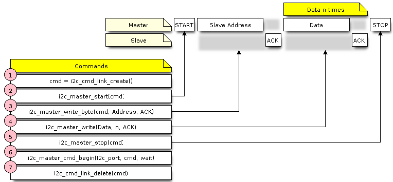
I2C command link - master write example
The following describes how a command link for a “master write” is set up and what comes inside:
Create a command link with
i2c_cmd_link_create().Then, populate it with the series of data to be sent to the slave:
Start bit -
i2c_master_start()Slave address -
i2c_master_write_byte(). The single byte address is provided as an argument of this function call.Data - One or more bytes as an argument of
i2c_master_write()Stop bit -
i2c_master_stop()
Both functions
i2c_master_write_byte()andi2c_master_write()have an additional argument specifying whether the master should ensure that it has received the ACK bit.Trigger the execution of the command link by I2C controller by calling
i2c_master_cmd_begin(). Once the execution is triggered, the command link cannot be modified.After the commands are transmitted, release the resources used by the command link by calling
i2c_cmd_link_delete().
Master Read
The example below shows how to build a command link for an I2C master to read n bytes from a slave.
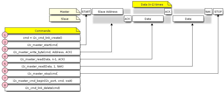
I2C command link - master read example
Compared to writing data, the command link is populated in Step 4 not with i2c_master_write... functions but with i2c_master_read_byte() and / or i2c_master_read(). Also, the last read in Step 5 is configured so that the master does not provide the ACK bit.
Indicating Write or Read
After sending a slave address (see Step 3 on both diagrams above), the master either writes or reads from the slave.
The information on what the master will actually do is hidden in the least significant bit of the slave’s address.
For this reason, the command link sent by the master to write data to the slave contains the address (ESP_SLAVE_ADDR << 1) | I2C_MASTER_WRITE and looks as follows:
i2c_master_write_byte(cmd, (ESP_SLAVE_ADDR << 1) | I2C_MASTER_WRITE, ACK_EN);
Likewise, the command link to read from the slave looks as follows:
i2c_master_write_byte(cmd, (ESP_SLAVE_ADDR << 1) | I2C_MASTER_READ, ACK_EN);
Communication as Slave
After installing the I2C driver, ESP32 is ready to communicate with other I2C devices.
The API provides the following functions for slaves
-
Whenever the master writes data to the slave, the slave will automatically store it in the receive buffer. This allows the slave application to call the function
i2c_slave_read_buffer()at its own discretion. This function also has a parameter to specify block time if no data is in the receive buffer. This will allow the slave application to wait with a specified timeout for data to arrive to the buffer. -
The send buffer is used to store all the data that the slave wants to send to the master in FIFO order. The data stays there until the master requests for it. The function
i2c_slave_write_buffer()has a parameter to specify block time if the send buffer is full. This will allow the slave application to wait with a specified timeout for the adequate amount of space to become available in the send buffer.
A code example showing how to use these functions can be found in peripherals/i2c.
Interrupt Handling
During driver installation, an interrupt handler is installed by default.
Customized Configuration
As mentioned at the end of Section Configuration, when the function i2c_param_config() initializes the driver configuration for an I2C port, it also sets several I2C communication parameters to default values defined in the I2C specification. Some other related parameters are pre-configured in registers of the I2C controller.
All these parameters can be changed to user-defined values by calling dedicated functions given in the table below. Please note that the timing values are defined in APB clock cycles. The frequency of APB is specified in I2C_APB_CLK_FREQ.
Parameters to Change |
Function |
|---|---|
High time and low time for SCL pulses |
|
SCL and SDA signal timing used during generation of start signals |
|
SCL and SDA signal timing used during generation of stop signals |
|
Timing relationship between SCL and SDA signals when slave samples, as well as when master toggles |
|
I2C timeout |
|
Choice between transmitting / receiving the LSB or MSB first, choose one of the modes defined in |
Each of the above functions has a _get_ counterpart to check the currently set value. For example, to check the I2C timeout value, call i2c_get_timeout().
To check the default parameter values which are set during the driver configuration process, please refer to the file driver/i2c.c and look for defines with the suffix _DEFAULT.
You can also select different pins for SDA and SCL signals and alter the configuration of pull-ups with the function i2c_set_pin(). If you want to modify already entered values, use the function i2c_param_config().
Note
ESP32’s internal pull-ups are in the range of tens of kOhm, which is, in most cases, insufficient for use as I2C pull-ups. Users are advised to use external pull-ups with values described in the I2C specification.
Error Handling
The majority of I2C driver functions either return ESP_OK on successful completion or a specific error code on failure. It is a good practice to always check the returned values and implement error handling. The driver also prints out log messages that contain error details, e.g., when checking the validity of entered configuration. For details please refer to the file driver/i2c.c and look for defines with the suffix _ERR_STR.
Use dedicated interrupts to capture communication failures. For instance, if a slave stretches the clock for too long while preparing the data to send back to master, the interrupt I2C_TIME_OUT_INT will be triggered. For detailed information, see Interrupt Handling.
In case of a communication failure, you can reset the internal hardware buffers by calling the functions i2c_reset_tx_fifo() and i2c_reset_rx_fifo() for the send and receive buffers respectively.
Delete Driver
When the I2C communication is established with the function i2c_driver_install() and is not required for some substantial amount of time, the driver may be deinitialized to release allocated resources by calling i2c_driver_delete().
Before calling i2c_driver_delete() to remove i2c driver, please make sure that all threads have stopped using the driver in any way, because this function does not guarantee thread safety.
Application Example
I2C examples: peripherals/i2c.
API Reference
Header File
Functions
-
esp_err_t i2c_driver_install(i2c_port_t i2c_num, i2c_mode_t mode, size_t slv_rx_buf_len, size_t slv_tx_buf_len, int intr_alloc_flags)
Install an I2C driver.
Note
Not all Espressif chips can support slave mode (e.g. ESP32C2)
Note
In master mode, if the cache is likely to be disabled(such as write flash) and the slave is time-sensitive,
ESP_INTR_FLAG_IRAMis suggested to be used. In this case, please use the memory allocated from internal RAM in i2c read and write function, because we can not access the psram(if psram is enabled) in interrupt handle function when cache is disabled.- Parameters
i2c_num – I2C port number
mode – I2C mode (either master or slave).
slv_rx_buf_len – Receiving buffer size. Only slave mode will use this value, it is ignored in master mode.
slv_tx_buf_len – Sending buffer size. Only slave mode will use this value, it is ignored in master mode.
intr_alloc_flags – Flags used to allocate the interrupt. One or multiple (ORred) ESP_INTR_FLAG_* values. See esp_intr_alloc.h for more info.
- Returns
ESP_OK Success
ESP_ERR_INVALID_ARG Parameter error
ESP_FAIL Driver installation error
-
esp_err_t i2c_driver_delete(i2c_port_t i2c_num)
Delete I2C driver.
Note
This function does not guarantee thread safety. Please make sure that no thread will continuously hold semaphores before calling the delete function.
- Parameters
i2c_num – I2C port to delete
- Returns
ESP_OK Success
ESP_ERR_INVALID_ARG Parameter error
-
esp_err_t i2c_param_config(i2c_port_t i2c_num, const i2c_config_t *i2c_conf)
Configure an I2C bus with the given configuration.
- Parameters
i2c_num – I2C port to configure
i2c_conf – Pointer to the I2C configuration
- Returns
ESP_OK Success
ESP_ERR_INVALID_ARG Parameter error
-
esp_err_t i2c_reset_tx_fifo(i2c_port_t i2c_num)
reset I2C tx hardware fifo
- Parameters
i2c_num – I2C port number
- Returns
ESP_OK Success
ESP_ERR_INVALID_ARG Parameter error
-
esp_err_t i2c_reset_rx_fifo(i2c_port_t i2c_num)
reset I2C rx fifo
- Parameters
i2c_num – I2C port number
- Returns
ESP_OK Success
ESP_ERR_INVALID_ARG Parameter error
-
esp_err_t i2c_set_pin(i2c_port_t i2c_num, int sda_io_num, int scl_io_num, bool sda_pullup_en, bool scl_pullup_en, i2c_mode_t mode)
Configure GPIO pins for I2C SCK and SDA signals.
- Parameters
i2c_num – I2C port number
sda_io_num – GPIO number for I2C SDA signal
scl_io_num – GPIO number for I2C SCL signal
sda_pullup_en – Enable the internal pullup for SDA pin
scl_pullup_en – Enable the internal pullup for SCL pin
mode – I2C mode
- Returns
ESP_OK Success
ESP_ERR_INVALID_ARG Parameter error
-
esp_err_t i2c_master_write_to_device(i2c_port_t i2c_num, uint8_t device_address, const uint8_t *write_buffer, size_t write_size, TickType_t ticks_to_wait)
Perform a write to a device connected to a particular I2C port. This function is a wrapper to
i2c_master_start(),i2c_master_write(),i2c_master_read(), etc… It shall only be called in I2C master mode.- Parameters
i2c_num – I2C port number to perform the transfer on
device_address – I2C device’s 7-bit address
write_buffer – Bytes to send on the bus
write_size – Size, in bytes, of the write buffer
ticks_to_wait – Maximum ticks to wait before issuing a timeout.
- Returns
ESP_OK Success
ESP_ERR_INVALID_ARG Parameter error
ESP_FAIL Sending command error, slave hasn’t ACK the transfer.
ESP_ERR_INVALID_STATE I2C driver not installed or not in master mode.
ESP_ERR_TIMEOUT Operation timeout because the bus is busy.
-
esp_err_t i2c_master_read_from_device(i2c_port_t i2c_num, uint8_t device_address, uint8_t *read_buffer, size_t read_size, TickType_t ticks_to_wait)
Perform a read to a device connected to a particular I2C port. This function is a wrapper to
i2c_master_start(),i2c_master_write(),i2c_master_read(), etc… It shall only be called in I2C master mode.- Parameters
i2c_num – I2C port number to perform the transfer on
device_address – I2C device’s 7-bit address
read_buffer – Buffer to store the bytes received on the bus
read_size – Size, in bytes, of the read buffer
ticks_to_wait – Maximum ticks to wait before issuing a timeout.
- Returns
ESP_OK Success
ESP_ERR_INVALID_ARG Parameter error
ESP_FAIL Sending command error, slave hasn’t ACK the transfer.
ESP_ERR_INVALID_STATE I2C driver not installed or not in master mode.
ESP_ERR_TIMEOUT Operation timeout because the bus is busy.
-
esp_err_t i2c_master_write_read_device(i2c_port_t i2c_num, uint8_t device_address, const uint8_t *write_buffer, size_t write_size, uint8_t *read_buffer, size_t read_size, TickType_t ticks_to_wait)
Perform a write followed by a read to a device on the I2C bus. A repeated start signal is used between the
writeandread, thus, the bus is not released until the two transactions are finished. This function is a wrapper toi2c_master_start(),i2c_master_write(),i2c_master_read(), etc… It shall only be called in I2C master mode.- Parameters
i2c_num – I2C port number to perform the transfer on
device_address – I2C device’s 7-bit address
write_buffer – Bytes to send on the bus
write_size – Size, in bytes, of the write buffer
read_buffer – Buffer to store the bytes received on the bus
read_size – Size, in bytes, of the read buffer
ticks_to_wait – Maximum ticks to wait before issuing a timeout.
- Returns
ESP_OK Success
ESP_ERR_INVALID_ARG Parameter error
ESP_FAIL Sending command error, slave hasn’t ACK the transfer.
ESP_ERR_INVALID_STATE I2C driver not installed or not in master mode.
ESP_ERR_TIMEOUT Operation timeout because the bus is busy.
-
i2c_cmd_handle_t i2c_cmd_link_create_static(uint8_t *buffer, uint32_t size)
Create and initialize an I2C commands list with a given buffer. All the allocations for data or signals (START, STOP, ACK, …) will be performed within this buffer. This buffer must be valid during the whole transaction. After finishing the I2C transactions, it is required to call
i2c_cmd_link_delete_static().Note
It is highly advised to not allocate this buffer on the stack. The size of the data used underneath may increase in the future, resulting in a possible stack overflow as the macro
I2C_LINK_RECOMMENDED_SIZEwould also return a bigger value. A better option is to use a buffer allocated statically or dynamically (withmalloc).- Parameters
buffer – Buffer to use for commands allocations
size – Size in bytes of the buffer
- Returns
Handle to the I2C command link or NULL if the buffer provided is too small, please use
I2C_LINK_RECOMMENDED_SIZEmacro to get the recommended size for the buffer.
-
i2c_cmd_handle_t i2c_cmd_link_create(void)
Create and initialize an I2C commands list with a given buffer. After finishing the I2C transactions, it is required to call
i2c_cmd_link_delete()to release and return the resources. The required bytes will be dynamically allocated.- Returns
Handle to the I2C command link or NULL in case of insufficient dynamic memory.
-
void i2c_cmd_link_delete_static(i2c_cmd_handle_t cmd_handle)
Free the I2C commands list allocated statically with
i2c_cmd_link_create_static.- Parameters
cmd_handle – I2C commands list allocated statically. This handle should be created thanks to
i2c_cmd_link_create_static()function
-
void i2c_cmd_link_delete(i2c_cmd_handle_t cmd_handle)
Free the I2C commands list.
- Parameters
cmd_handle – I2C commands list. This handle should be created thanks to
i2c_cmd_link_create()function
-
esp_err_t i2c_master_start(i2c_cmd_handle_t cmd_handle)
Queue a “START signal” to the given commands list. This function shall only be called in I2C master mode. Call
i2c_master_cmd_begin()to send all the queued commands.- Parameters
cmd_handle – I2C commands list
- Returns
ESP_OK Success
ESP_ERR_INVALID_ARG Parameter error
ESP_ERR_NO_MEM The static buffer used to create
cmd_handleris too smallESP_FAIL No more memory left on the heap
-
esp_err_t i2c_master_write_byte(i2c_cmd_handle_t cmd_handle, uint8_t data, bool ack_en)
Queue a “write byte” command to the commands list. A single byte will be sent on the I2C port. This function shall only be called in I2C master mode. Call
i2c_master_cmd_begin()to send all queued commands.- Parameters
cmd_handle – I2C commands list
data – Byte to send on the port
ack_en – Enable ACK signal
- Returns
ESP_OK Success
ESP_ERR_INVALID_ARG Parameter error
ESP_ERR_NO_MEM The static buffer used to create
cmd_handleris too smallESP_FAIL No more memory left on the heap
-
esp_err_t i2c_master_write(i2c_cmd_handle_t cmd_handle, const uint8_t *data, size_t data_len, bool ack_en)
Queue a “write (multiple) bytes” command to the commands list. This function shall only be called in I2C master mode. Call
i2c_master_cmd_begin()to send all queued commands.- Parameters
cmd_handle – I2C commands list
data – Bytes to send. This buffer shall remain valid until the transaction is finished. If the PSRAM is enabled and
intr_flagis set toESP_INTR_FLAG_IRAM,datashould be allocated from internal RAM.data_len – Length, in bytes, of the data buffer
ack_en – Enable ACK signal
- Returns
ESP_OK Success
ESP_ERR_INVALID_ARG Parameter error
ESP_ERR_NO_MEM The static buffer used to create
cmd_handleris too smallESP_FAIL No more memory left on the heap
-
esp_err_t i2c_master_read_byte(i2c_cmd_handle_t cmd_handle, uint8_t *data, i2c_ack_type_t ack)
Queue a “read byte” command to the commands list. A single byte will be read on the I2C bus. This function shall only be called in I2C master mode. Call
i2c_master_cmd_begin()to send all queued commands.- Parameters
cmd_handle – I2C commands list
data – Pointer where the received byte will the stored. This buffer shall remain valid until the transaction is finished.
ack – ACK signal
- Returns
ESP_OK Success
ESP_ERR_INVALID_ARG Parameter error
ESP_ERR_NO_MEM The static buffer used to create
cmd_handleris too smallESP_FAIL No more memory left on the heap
-
esp_err_t i2c_master_read(i2c_cmd_handle_t cmd_handle, uint8_t *data, size_t data_len, i2c_ack_type_t ack)
Queue a “read (multiple) bytes” command to the commands list. Multiple bytes will be read on the I2C bus. This function shall only be called in I2C master mode. Call
i2c_master_cmd_begin()to send all queued commands.- Parameters
cmd_handle – I2C commands list
data – Pointer where the received bytes will the stored. This buffer shall remain valid until the transaction is finished.
data_len – Size, in bytes, of the
databufferack – ACK signal
- Returns
ESP_OK Success
ESP_ERR_INVALID_ARG Parameter error
ESP_ERR_NO_MEM The static buffer used to create
cmd_handleris too smallESP_FAIL No more memory left on the heap
-
esp_err_t i2c_master_stop(i2c_cmd_handle_t cmd_handle)
Queue a “STOP signal” to the given commands list. This function shall only be called in I2C master mode. Call
i2c_master_cmd_begin()to send all the queued commands.- Parameters
cmd_handle – I2C commands list
- Returns
ESP_OK Success
ESP_ERR_INVALID_ARG Parameter error
ESP_ERR_NO_MEM The static buffer used to create
cmd_handleris too smallESP_FAIL No more memory left on the heap
-
esp_err_t i2c_master_cmd_begin(i2c_port_t i2c_num, i2c_cmd_handle_t cmd_handle, TickType_t ticks_to_wait)
Send all the queued commands on the I2C bus, in master mode. The task will be blocked until all the commands have been sent out. The I2C port is protected by mutex, so this function is thread-safe. This function shall only be called in I2C master mode.
- Parameters
i2c_num – I2C port number
cmd_handle – I2C commands list
ticks_to_wait – Maximum ticks to wait before issuing a timeout.
- Returns
ESP_OK Success
ESP_ERR_INVALID_ARG Parameter error
ESP_FAIL Sending command error, slave hasn’t ACK the transfer.
ESP_ERR_INVALID_STATE I2C driver not installed or not in master mode.
ESP_ERR_TIMEOUT Operation timeout because the bus is busy.
-
int i2c_slave_write_buffer(i2c_port_t i2c_num, const uint8_t *data, int size, TickType_t ticks_to_wait)
Write bytes to internal ringbuffer of the I2C slave data. When the TX fifo empty, the ISR will fill the hardware FIFO with the internal ringbuffer’s data.
Note
This function shall only be called in I2C slave mode.
- Parameters
i2c_num – I2C port number
data – Bytes to write into internal buffer
size – Size, in bytes, of
databufferticks_to_wait – Maximum ticks to wait.
- Returns
ESP_FAIL (-1) Parameter error
Other (>=0) The number of data bytes pushed to the I2C slave buffer.
-
int i2c_slave_read_buffer(i2c_port_t i2c_num, uint8_t *data, size_t max_size, TickType_t ticks_to_wait)
Read bytes from I2C internal buffer. When the I2C bus receives data, the ISR will copy them from the hardware RX FIFO to the internal ringbuffer. Calling this function will then copy bytes from the internal ringbuffer to the
datauser buffer.Note
This function shall only be called in I2C slave mode.
- Parameters
i2c_num – I2C port number
data – Buffer to fill with ringbuffer’s bytes
max_size – Maximum bytes to read
ticks_to_wait – Maximum waiting ticks
- Returns
ESP_FAIL(-1) Parameter error
Others(>=0) The number of data bytes read from I2C slave buffer.
-
esp_err_t i2c_set_period(i2c_port_t i2c_num, int high_period, int low_period)
Set I2C master clock period.
- Parameters
i2c_num – I2C port number
high_period – Clock cycle number during SCL is high level, high_period is a 14 bit value
low_period – Clock cycle number during SCL is low level, low_period is a 14 bit value
- Returns
ESP_OK Success
ESP_ERR_INVALID_ARG Parameter error
-
esp_err_t i2c_get_period(i2c_port_t i2c_num, int *high_period, int *low_period)
Get I2C master clock period.
- Parameters
i2c_num – I2C port number
high_period – pointer to get clock cycle number during SCL is high level, will get a 14 bit value
low_period – pointer to get clock cycle number during SCL is low level, will get a 14 bit value
- Returns
ESP_OK Success
ESP_ERR_INVALID_ARG Parameter error
-
esp_err_t i2c_filter_enable(i2c_port_t i2c_num, uint8_t cyc_num)
Enable hardware filter on I2C bus Sometimes the I2C bus is disturbed by high frequency noise(about 20ns), or the rising edge of the SCL clock is very slow, these may cause the master state machine to break. Enable hardware filter can filter out high frequency interference and make the master more stable.
Note
Enable filter will slow down the SCL clock.
- Parameters
i2c_num – I2C port number to filter
cyc_num – the APB cycles need to be filtered (0<= cyc_num <=7). When the period of a pulse is less than cyc_num * APB_cycle, the I2C controller will ignore this pulse.
- Returns
ESP_OK Success
ESP_ERR_INVALID_ARG Parameter error
-
esp_err_t i2c_filter_disable(i2c_port_t i2c_num)
Disable filter on I2C bus.
- Parameters
i2c_num – I2C port number
- Returns
ESP_OK Success
ESP_ERR_INVALID_ARG Parameter error
-
esp_err_t i2c_set_start_timing(i2c_port_t i2c_num, int setup_time, int hold_time)
set I2C master start signal timing
- Parameters
i2c_num – I2C port number
setup_time – clock number between the falling-edge of SDA and rising-edge of SCL for start mark, it’s a 10-bit value.
hold_time – clock num between the falling-edge of SDA and falling-edge of SCL for start mark, it’s a 10-bit value.
- Returns
ESP_OK Success
ESP_ERR_INVALID_ARG Parameter error
-
esp_err_t i2c_get_start_timing(i2c_port_t i2c_num, int *setup_time, int *hold_time)
get I2C master start signal timing
- Parameters
i2c_num – I2C port number
setup_time – pointer to get setup time
hold_time – pointer to get hold time
- Returns
ESP_OK Success
ESP_ERR_INVALID_ARG Parameter error
-
esp_err_t i2c_set_stop_timing(i2c_port_t i2c_num, int setup_time, int hold_time)
set I2C master stop signal timing
- Parameters
i2c_num – I2C port number
setup_time – clock num between the rising-edge of SCL and the rising-edge of SDA, it’s a 10-bit value.
hold_time – clock number after the STOP bit’s rising-edge, it’s a 14-bit value.
- Returns
ESP_OK Success
ESP_ERR_INVALID_ARG Parameter error
-
esp_err_t i2c_get_stop_timing(i2c_port_t i2c_num, int *setup_time, int *hold_time)
get I2C master stop signal timing
- Parameters
i2c_num – I2C port number
setup_time – pointer to get setup time.
hold_time – pointer to get hold time.
- Returns
ESP_OK Success
ESP_ERR_INVALID_ARG Parameter error
-
esp_err_t i2c_set_data_timing(i2c_port_t i2c_num, int sample_time, int hold_time)
set I2C data signal timing
- Parameters
i2c_num – I2C port number
sample_time – clock number I2C used to sample data on SDA after the rising-edge of SCL, it’s a 10-bit value
hold_time – clock number I2C used to hold the data after the falling-edge of SCL, it’s a 10-bit value
- Returns
ESP_OK Success
ESP_ERR_INVALID_ARG Parameter error
-
esp_err_t i2c_get_data_timing(i2c_port_t i2c_num, int *sample_time, int *hold_time)
get I2C data signal timing
- Parameters
i2c_num – I2C port number
sample_time – pointer to get sample time
hold_time – pointer to get hold time
- Returns
ESP_OK Success
ESP_ERR_INVALID_ARG Parameter error
-
esp_err_t i2c_set_timeout(i2c_port_t i2c_num, int timeout)
set I2C timeout value
- Parameters
i2c_num – I2C port number
timeout – timeout value for I2C bus (unit: APB 80Mhz clock cycle)
- Returns
ESP_OK Success
ESP_ERR_INVALID_ARG Parameter error
-
esp_err_t i2c_get_timeout(i2c_port_t i2c_num, int *timeout)
get I2C timeout value
- Parameters
i2c_num – I2C port number
timeout – pointer to get timeout value
- Returns
ESP_OK Success
ESP_ERR_INVALID_ARG Parameter error
-
esp_err_t i2c_set_data_mode(i2c_port_t i2c_num, i2c_trans_mode_t tx_trans_mode, i2c_trans_mode_t rx_trans_mode)
set I2C data transfer mode
- Parameters
i2c_num – I2C port number
tx_trans_mode – I2C sending data mode
rx_trans_mode – I2C receving data mode
- Returns
ESP_OK Success
ESP_ERR_INVALID_ARG Parameter error
-
esp_err_t i2c_get_data_mode(i2c_port_t i2c_num, i2c_trans_mode_t *tx_trans_mode, i2c_trans_mode_t *rx_trans_mode)
get I2C data transfer mode
- Parameters
i2c_num – I2C port number
tx_trans_mode – pointer to get I2C sending data mode
rx_trans_mode – pointer to get I2C receiving data mode
- Returns
ESP_OK Success
ESP_ERR_INVALID_ARG Parameter error
Structures
-
struct i2c_config_t
I2C initialization parameters.
Public Members
-
i2c_mode_t mode
I2C mode
-
int sda_io_num
GPIO number for I2C sda signal
-
int scl_io_num
GPIO number for I2C scl signal
-
bool sda_pullup_en
Internal GPIO pull mode for I2C sda signal
-
bool scl_pullup_en
Internal GPIO pull mode for I2C scl signal
-
uint32_t clk_speed
I2C clock frequency for master mode, (no higher than 1MHz for now)
-
struct i2c_config_t::[anonymous]::[anonymous] master
I2C master config
-
uint8_t addr_10bit_en
I2C 10bit address mode enable for slave mode
-
uint16_t slave_addr
I2C address for slave mode
-
uint32_t maximum_speed
I2C expected clock speed from SCL.
-
struct i2c_config_t::[anonymous]::[anonymous] slave
I2C slave config
-
uint32_t clk_flags
Bitwise of
I2C_SCLK_SRC_FLAG_**FOR_DFS**for clk source choice
-
i2c_mode_t mode
Macros
-
I2C_APB_CLK_FREQ
I2C source clock is APB clock, 80MHz
-
I2C_NUM_MAX
I2C port max
-
I2C_NUM_0
I2C port 0
-
I2C_NUM_1
I2C port 1
-
I2C_SCLK_SRC_FLAG_FOR_NOMAL
Any one clock source that is available for the specified frequency may be choosen
-
I2C_SCLK_SRC_FLAG_AWARE_DFS
For REF tick clock, it won’t change with APB.
-
I2C_SCLK_SRC_FLAG_LIGHT_SLEEP
For light sleep mode.
-
I2C_INTERNAL_STRUCT_SIZE
Minimum size, in bytes, of the internal private structure used to describe I2C commands link.
-
I2C_LINK_RECOMMENDED_SIZE(TRANSACTIONS)
The following macro is used to determine the recommended size of the buffer to pass to
i2c_cmd_link_create_static()function. It requires one parameter,TRANSACTIONS, describing the number of transactions intended to be performed on the I2C port. For example, if one wants to perform a read on an I2C device register,TRANSACTIONSmust be at least 2, because the commands required are the following:write device register
read register content
Signals such as “(repeated) start”, “stop”, “nack”, “ack” shall not be counted.
Header File
Type Definitions
-
typedef int i2c_port_t
I2C port number, can be I2C_NUM_0 ~ (I2C_NUM_MAX-1).
-
typedef soc_periph_i2c_clk_src_t i2c_clock_source_t
I2C group clock source.
Enumerations
-
enum i2c_mode_t
Values:
-
enumerator I2C_MODE_SLAVE
I2C slave mode
-
enumerator I2C_MODE_MASTER
I2C master mode
-
enumerator I2C_MODE_MAX
-
enumerator I2C_MODE_SLAVE
-
enum i2c_rw_t
Values:
-
enumerator I2C_MASTER_WRITE
I2C write data
-
enumerator I2C_MASTER_READ
I2C read data
-
enumerator I2C_MASTER_WRITE
-
enum i2c_trans_mode_t
Values:
-
enumerator I2C_DATA_MODE_MSB_FIRST
I2C data msb first
-
enumerator I2C_DATA_MODE_LSB_FIRST
I2C data lsb first
-
enumerator I2C_DATA_MODE_MAX
-
enumerator I2C_DATA_MODE_MSB_FIRST