Remote Control Transceiver (RMT)
Introduction
The RMT (Remote Control Transceiver) peripheral was designed to act as an infrared transceiver. However, due to the flexibility of its data format, the functionality of RMT can be extended to a versatile and general purpose transceiver. From the perspective of network layering, the RMT hardware contains both physical and data link layer. The physical layer defines the communication media and bit signal representation. The data link layer defines the format of an RMT frame. The minimal data unit in the frame is called RMT symbol, which is represented by rmt_symbol_word_t in the driver.
ESP32-C3 contains multiple channels in the RMT peripheral. 1 Each channel can be configured as either transmitter or receiver, independently.
Typically, the RMT peripheral can be used in the following scenarios:
Transmit or receive infrared signals, with any IR protocols, e.g. NEC
General purpose sequence generator
Transmit signals in a hardware controlled loop, with finite or infinite number of times
Multi-channel simultaneous transmission
Modulate the carrier to the output signal or demodulate the carrier from the input signal
Layout of RMT Symbols
The RMT hardware defines data in its own pattern – the RMT symbol. Each symbol consists of two pairs of two values. The first value in a pair describes the signal duration in RMT ticks and is 15 bits long. The second provides the signal level (high or low) and is contained in a single bit, as shown below:
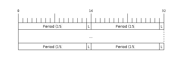
Structure of RMT symbols (L - signal level)
RMT Transmitter Overview
The data path and control path of an RMT TX channel is illustrated in the figure below:
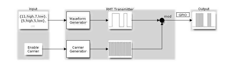
RMT Transmitter Overview
The driver will encode user’s data into RMT data format, then the RMT transmitter can generate the waveforms according to the encoding artifacts. It is also possible to modulate a high frequency carrier signal before being routed to a GPIO pad.
RMT Receiver Overview
The data path and control path of an RMT RX channel is illustrated in the figure below:
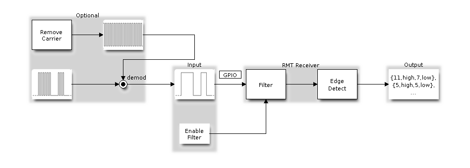
RMT Receiver Overview
The RMT receiver can sample incoming signals into RMT data format, and store the data in memory. It’s feasible to tell the receiver the basic characteristics of the incoming signal, so that the signal’s stop condition can be recognized, and signal glitches and noise can be filtered out. The RMT peripheral also supports demodulating the high frequency carrier from the base signal.
Functional Overview
Description of the RMT functionality is divided into the following sections:
Resource Allocation - covers how to allocate RMT channels with properly set of configurations. It also covers how to recycle the resources when they finished working.
Carrier Modulation and Demodulation - describes how to modulate carrier for TX channel and demodulate carrier for RX channel.
Register Event Callbacks - covers how to hook user specific code to RMT channel specific events.
Enable and Disable channel - shows how to enable and disable the RMT channel.
Initiate TX Transaction - describes the steps to initiate a transaction for TX channel.
Initiate RX Transaction - describes the steps to initiate a transaction for RX channel.
Multiple Channels Simultaneous Transmission - describes how to collect multiple channels into a sync group and start transaction at the same time.
RMT Encoder - focuses on how to write a customized encoder in a combination way, with the help of the primitive encoders provided by the driver.
Power Management - describes how different source clock will affect power consumption.
IRAM Safe - describes tips on how to make the RMT interrupt work better along with a disabled cache.
Thread Safety - lists which APIs are guaranteed to be thread safe by the driver.
Kconfig Options - lists the supported Kconfig options that can bring different effects to the driver.
Resource Allocation
Both RMT TX and RX channels are represented by rmt_channel_handle_t in the driver. The available channels are managed in a resource pool, which will hand out a free channel on request.
Install RMT TX Channel
To install an RMT TX channel, there’s a configuration structure that needs to be given in advance: rmt_tx_channel_config_t:
rmt_tx_channel_config_t::gpio_numsets the GPIO number used by the transmitter.rmt_tx_channel_config_t::clk_srcselects the source clock for the RMT channel. The available clocks are listed inrmt_clock_source_t. Note that, the selected clock will also be used by other channels, which means user should ensure this configuration is same when allocating other channels, regardless of TX or RX. For the effect on power consumption of different clock source, please refer to Power Management section.rmt_tx_channel_config_t::resolution_hzsets the resolution of the internal tick counter. The timing parameter of RMT signal is calculated based on this tick.rmt_tx_channel_config_t::mem_block_symbolssets the size of the dedicated memory block or DMA buffer that is used to store RMT encoding artifacts.rmt_tx_channel_config_t::trans_queue_depthsets the depth of internal transaction queue, the deeper the queue, the more transactions can be prepared in the backlog.rmt_tx_channel_config_t::invert_outis used to decide whether to invert the RMT signal before sending it to the GPIO pad.rmt_tx_channel_config_t::with_dmais used to indicate if the channel needs a DMA backend. A channel with DMA attached can offload the CPU by a lot. However, DMA backend is not available on all ESP chips, please refer to [TRM] before you enable this option. Or you might encounterESP_ERR_NOT_SUPPORTEDerror.rmt_tx_channel_config_t::io_loop_backenables both the GPIO’s input and output ability through the GPIO matrix peripheral. Meanwhile, if both TX and RX channels are bound to the same GPIO, then monitoring of the data transmission line can be realized.rmt_tx_channel_config_t::io_od_modeconfigures the GPIO as open-drain mode. It is useful for simulating bi-directional buses, sucn as 1-wire bus, combined withrmt_tx_channel_config_t::io_loop_back.
Once the rmt_tx_channel_config_t structure is populated with mandatory parameters, users can call rmt_new_tx_channel() to allocate and initialize a TX channel. This function will return an RMT channel handle if it runs correctly. Specifically, when there are no more free channels in the RMT resource pool, this function will return ESP_ERR_NOT_FOUND error. If some feature (e.g. DMA backend) is not supported by hardware, it will return ESP_ERR_NOT_SUPPORTED error.
rmt_channel_handle_t tx_chan = NULL;
rmt_tx_channel_config_t tx_chan_config = {
    .clk_src = RMT_CLK_SRC_DEFAULT,       // select source clock
    .gpio_num = 0,                    // GPIO number
    .mem_block_symbols = 64,          // memory block size, 64 * 4 = 256Bytes
    .resolution_hz = 1 * 1000 * 1000, // 1MHz tick resolution, i.e. 1 tick = 1us
    .trans_queue_depth = 4,           // set the number of transactions that can pend in the background
    .flags.invert_out = false,        // don't invert output signal
    .flags.with_dma = false,          // don't need DMA backend
};
ESP_ERROR_CHECK(rmt_new_tx_channel(&tx_chan_config, &tx_chan));
Install RMT RX Channel
To install an RMT RX channel, there’s a configuration structure that needs to be given in advance: rmt_rx_channel_config_t:
rmt_rx_channel_config_t::gpio_numsets the GPIO number used by the receiver.rmt_rx_channel_config_t::clk_srcselects the source clock for the RMT channel. The available clocks are listed inrmt_clock_source_t. Note that, the selected clock will also be used by other channels, which means user should ensure this configuration is same when allocating other channels, regardless of TX or RX. For the effect on power consumption of different clock source, please refer to Power Management section.rmt_rx_channel_config_t::resolution_hzsets the resolution of the internal tick counter. The timing parameter of RMT signal is calculated based on this tick.rmt_rx_channel_config_t::mem_block_symbolssets the size of the dedicated memory block or DMA buffer that used to store RMT encoding artifacts.rmt_rx_channel_config_t::invert_inis used to decide whether to invert the input signals before they going into RMT receiver. The inversion is done by GPIO matrix instead of by the RMT peripheral.rmt_rx_channel_config_t::with_dmais used to indicate if the channel needs a DMA backend. A channel with DMA attached can offload the CPU by a lot. However, DMA backend is not available on all ESP chips, please refer to [TRM] before you enable this option. Or you might encounterESP_ERR_NOT_SUPPORTEDerror.rmt_rx_channel_config_t::io_loop_backis for debugging purposes only. It enables both the GPIO’s input and output ability through the GPIO matrix peripheral. Meanwhile, if both TX and RX channels are bound to the same GPIO, then monitoring of the data transmission line can be realized.
Once the rmt_rx_channel_config_t structure is populated with mandatory parameters, users can call rmt_new_rx_channel() to allocate and initialize a RX channel. This function will return an RMT channel handle if it runs correctly. Specifically, when there are no more free channels in the RMT resource pool, this function will return ESP_ERR_NOT_FOUND error. If some feature (e.g. DMA backend) is not supported by hardware, it will return ESP_ERR_NOT_SUPPORTED error.
rmt_channel_handle_t rx_chan = NULL;
rmt_rx_channel_config_t rx_chan_config = {
    .clk_src = RMT_CLK_SRC_DEFAULT,       // select source clock
    .resolution_hz = 1 * 1000 * 1000, // 1MHz tick resolution, i.e. 1 tick = 1us
    .mem_block_symbols = 64,          // memory block size, 64 * 4 = 256Bytes
    .gpio_num = 2,                    // GPIO number
    .flags.invert_in = false,         // don't invert input signal
    .flags.with_dma = false,          // don't need DMA backend
};
ESP_ERROR_CHECK(rmt_new_rx_channel(&rx_chan_config, &rx_chan));
Uninstall RMT Channel
If a previously installed RMT channel is no longer needed, it’s recommended to recycle the resources by calling rmt_del_channel(), which in return allows the underlying hardware to be usable for other purposes.
Carrier Modulation and Demodulation
The RMT transmitter can generate a carrier wave and modulate it onto the base signal. Compared to the base signal, the carrier frequency is usually high. In addition, user can only set the frequency and duty cycle for the carrier. The RMT receiver can demodulate the carrier from the incoming signal. Note that, carrier modulation and demodulation is not supported on all ESP chips, please refer to [TRM] before configuring the carrier, or you might encounter a ESP_ERR_NOT_SUPPORTED error.
Carrier related configurations lie in rmt_carrier_config_t:
rmt_carrier_config_t::frequency_hzsets the carrier frequency, in Hz.rmt_carrier_config_t::duty_cyclesets the carrier duty cycle.rmt_carrier_config_t::polarity_active_lowsets the carrier polarity, i.e. on which level the carrier is applied.rmt_carrier_config_t::always_onsets whether to output the carrier even when the data transmission has finished. This configuration is only valid for TX channel.
Note
For RX channel, we shouldn’t set the carrier frequency exactly to the theoretical value. It’s recommended to leave a tolerance for the carrier frequency. For example, in the snippet below, we set the frequency to 25KHz, instead of the 38KHz that configured on the TX side. The reason is that reflection and refraction will occur when a signal travels through the air, leading to the a distortion on the receiver side.
rmt_carrier_config_t tx_carrier_cfg = {
    .duty_cycle = 0.33,                 // duty cycle 33%
    .frequency_hz = 38000,              // 38KHz
    .flags.polarity_active_low = false, // carrier should modulated to high level
};
// modulate carrier to TX channel
ESP_ERROR_CHECK(rmt_apply_carrier(tx_chan, &tx_carrier_cfg));

rmt_carrier_config_t rx_carrier_cfg = {
    .duty_cycle = 0.33,                 // duty cycle 33%
    .frequency_hz = 25000,              // 25KHz carrier, should be smaller than transmitter's carrier frequency
    .flags.polarity_active_low = false, // the carrier is modulated to high level
};
// demodulate carrier from RX channel
ESP_ERROR_CHECK(rmt_apply_carrier(rx_chan, &rx_carrier_cfg));
Register Event Callbacks
When an RMT channel finishes transmitting or receiving, a specific event will be generated and notify the CPU by interrupt. If you have some function that needs to be called when those events occurred, you can hook your function to the ISR (Interrupt Service Routine) by calling rmt_tx_register_event_callbacks() and rmt_rx_register_event_callbacks() for TX and RX channel respectively. Since the registered callback functions are called in the interrupt context, user should ensure the callback function doesn’t attempt to block (e.g. by making sure that only FreeRTOS APIs with ISR suffix are called from within the function). The callback function has a boolean return value, to tell the caller whether a high priority task is woke up by it.
TX channel supported event callbacks are listed in the rmt_tx_event_callbacks_t:
rmt_tx_event_callbacks_t::on_trans_donesets a callback function for trans done event. The function prototype is declared inrmt_tx_done_callback_t.
RX channel supported event callbacks are listed in the rmt_rx_event_callbacks_t:
rmt_rx_event_callbacks_t::on_recv_donesets a callback function for receive complete event. The function prototype is declared inrmt_rx_done_callback_t.
User can save own context in rmt_tx_register_event_callbacks() and rmt_rx_register_event_callbacks() as well, via the parameter user_data. The user data will be directly passed to each callback function.
In the callback function, users can fetch the event specific data that is filled by the driver in the edata. Note that the edata pointer is only valid for the duration of the callback.
The TX done event data is defined in rmt_tx_done_event_data_t:
rmt_tx_done_event_data_t::num_symbolstells the number of transmitted RMT symbols. This also reflects the size of encoding artifacts.
The RX complete event data is defined in rmt_rx_done_event_data_t:
rmt_rx_done_event_data_t::received_symbolspoints to the received RMT symbols. These symbols are saved in thebufferparameter ofrmt_receive()function. User shouldn’t free this receive buffer before the callback returns.rmt_rx_done_event_data_t::num_symbolstells the number of received RMT symbols. This value won’t be bigger thanbuffer_sizeparameter ofrmt_receive()function. If thebuffer_sizeis not sufficient to accommodate all the received RMT symbols, the driver will truncate it.
Enable and Disable channel
rmt_enable() must be called in advanced before transmitting or receiving RMT symbols. For transmitters, enabling a channel will enable a specific interrupt and prepare the hardware to dispatch transactions. For RX channels, enabling a channel will enable an interrupt, but the receiver is not started during this time, as it has no idea about the characteristics of the incoming signals. The receiver will be started in rmt_receive().
rmt_disable() does the opposite work by disabling the interrupt and clearing pending status. The transmitter and receiver will be disabled as well.
ESP_ERROR_CHECK(rmt_enable(tx_chan));
ESP_ERROR_CHECK(rmt_enable(rx_chan));
Initiate TX Transaction
RMT is a special communication peripheral as it’s unable to transmit raw byte streams like SPI and I2C. RMT can only send data in its own format rmt_symbol_word_t. However, the hardware doesn’t help to convert the user data into RMT symbols, this can only be done in software — by the so-called RMT Encoder. The encoder is responsible for encoding user data into RMT symbols and then write to RMT memory block or DMA buffer. For how to create an RMT encoder, please refer to RMT Encoder.
Once we got an encoder, we can initiate a TX transaction by calling rmt_transmit(). This function takes several positional parameters like channel handle, encoder handle, payload buffer. Besides that, we also need to provide a transmission specific configuration in rmt_transmit_config_t:
rmt_transmit_config_t::loop_countsets the number of transmission loop. After the transmitter finished one round of transmission, it can restart the same transmission again if this value is not set to zero. As the loop is controlled by hardware, the RMT channel can be used to generate many periodic sequences at the cost of a very little CPU intervention. Specially, settingrmt_transmit_config_t::loop_countto -1 means an infinite loop transmission. In this situation, the channel won’t stop until manually call ofrmt_disable(). And the trans done event won’t be generated as well. Ifrmt_transmit_config_t::loop_countis set to a positive number, the trans done event won’t be generated until target number of loop transmission have finished. Note that, the loop transmit feature is not supported on all ESP chips, please refer to [TRM] before you configure this option. Or you might encounterESP_ERR_NOT_SUPPORTEDerror.rmt_transmit_config_t::eot_levelsets the output level when the transmitter finishes working or stops working by callingrmt_disable().
Note
There’s a limitation in the transmission size if the rmt_transmit_config_t::loop_count is set to non-zero (i.e. to enable the loop feature). The encoded RMT symbols should not exceed the capacity of RMT hardware memory block size. Or you might see error message like encoding artifacts can't exceed hw memory block for loop transmission. If you have to start a large transaction by loop, you can try either:
Increase the
rmt_tx_channel_config_t::mem_block_symbols. This approach doesn’t work if the DMA backend is also enabled.Customize an encoder and construct a forever loop in the encoding function. See also RMT Encoder.
Internally, rmt_transmit() will construct a transaction descriptor and send to a job queue, which will be dispatched in the ISR. So it is possible that the transaction is not started yet when rmt_transmit() returns. To ensure all pending transaction to complete, user can use rmt_tx_wait_all_done().
Multiple Channels Simultaneous Transmission
In some real-time control applications, we don’t want any time drift in between when startup multiple TX channels. For example, to make two robotic arms move simultaneously. The RMT driver can help to manage this by creating a so-called Sync Manager. The sync manager is represented by rmt_sync_manager_handle_t in the driver. The procedure of RMT sync transmission is shown as follows:
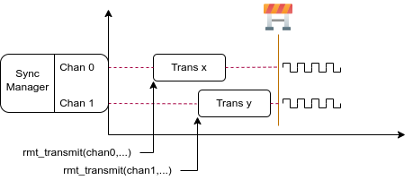
RMT TX Sync
Install RMT Sync Manager
To create a sync manager, user needs to tell which channels are going to be managed in the rmt_sync_manager_config_t:
rmt_sync_manager_config_t::tx_channel_arraypoints to the array of TX channels to be managed.rmt_sync_manager_config_t::array_sizesets the number of channels to be managed.
rmt_new_sync_manager() can return a manager handle on success. This function could also fail due to various errors such as invalid arguments, etc. Specially, when the sync manager has been installed before, and there’re no hardware resources to create another manager, this function will report ESP_ERR_NOT_FOUND error. In addition, if the sync manager is not supported by the hardware, it will report ESP_ERR_NOT_SUPPORTED error. Please refer to [TRM] before using the sync manager feature.
Start Transmission Simultaneously
For any managed TX channel, it won’t start the machine until all the channels in the rmt_sync_manager_config_t::tx_channel_array are called with rmt_transmit(). Before that, the channel is just put in a waiting state. Different channel usually take different time to finish the job if the transaction is different, which results in a loss of sync. So user needs to call rmt_sync_reset() to pull the channels back to the starting line again before restarting a simultaneous transmission.
Calling rmt_del_sync_manager() can recycle the sync manager and enable the channels to initiate transactions independently afterwards.
rmt_channel_handle_t tx_channels[2] = {NULL}; // declare two channels
int tx_gpio_number[2] = {0, 2};
// install channels one by one
for (int i = 0; i < 2; i++) {
    rmt_tx_channel_config_t tx_chan_config = {
        .clk_src = RMT_CLK_SRC_DEFAULT,       // select source clock
        .gpio_num = tx_gpio_number[i],    // GPIO number
        .mem_block_symbols = 64,          // memory block size, 64 * 4 = 256Bytes
        .resolution_hz = 1 * 1000 * 1000, // 1MHz resolution
        .trans_queue_depth = 1,           // set the number of transactions that can pend in the background
    };
    ESP_ERROR_CHECK(rmt_new_tx_channel(&tx_chan_config, &tx_channels[i]));
}
// install sync manager
rmt_sync_manager_handle_t synchro = NULL;
rmt_sync_manager_config_t synchro_config = {
    .tx_channel_array = tx_channels,
    .array_size = sizeof(tx_channels) / sizeof(tx_channels[0]),
};
ESP_ERROR_CHECK(rmt_new_sync_manager(&synchro_config, &synchro));

ESP_ERROR_CHECK(rmt_transmit(tx_channels[0], led_strip_encoders[0], led_data, led_num * 3, &transmit_config));
// tx_channels[0] won't start transmission until call of `rmt_transmit()` for tx_channels[1] returns
ESP_ERROR_CHECK(rmt_transmit(tx_channels[1], led_strip_encoders[1], led_data, led_num * 3, &transmit_config));
Initiate RX Transaction
As also discussed in the Enable and Disable channel, the RX channel still doesn’t get ready to receive RMT symbols even user calls rmt_enable(). User needs to specify the basic characteristics of the incoming signals in rmt_receive_config_t:
rmt_receive_config_t::signal_range_min_nsspecifies the minimal valid pulse duration (either high or low level). A pulse whose width is smaller than this value will be treated as glitch and ignored by the hardware.rmt_receive_config_t::signal_range_max_nsspecifies the maximum valid pulse duration (either high or low level). A pulse whose width is bigger than this value will be treated as Stop Signal, and the receiver will generate receive complete event immediately.
The RMT receiver will start the RX machine after user calls rmt_receive() with the provided configuration above. Note that, this configuration is transaction specific, which means, to start a new round of reception, user needs to sets the rmt_receive_config_t again. The receiver saves the incoming signals into its internal memory block or DMA buffer, in the format of rmt_symbol_word_t.
Due to the limited size of memory block, the RMT receiver will notify the driver to copy away the accumulated symbols in a ping-pong way.
The copy destination should be provided in the buffer parameter of rmt_receive() function. If this buffer size is not sufficient, the receiver can continue to work but later incoming symbols will be dropped and report an error message: user buffer too small, received symbols truncated. Please take care of the lifecycle of the buffer parameter, user shouldn’t recycle the buffer before the receiver finished or stopped working.
The receiver will be stopped by the driver when it finishes working (i.e. received a signal whose duration is bigger than rmt_receive_config_t::signal_range_max_ns). User needs to call rmt_receive() again to restart the receiver, is necessary. User can get the received data in the rmt_rx_event_callbacks_t::on_recv_done callback. See also Register Event Callbacks for more information.
static bool example_rmt_rx_done_callback(rmt_channel_handle_t channel, const rmt_rx_done_event_data_t *edata, void *user_data)
{
    BaseType_t high_task_wakeup = pdFALSE;
    QueueHandle_t receive_queue = (QueueHandle_t)user_data;
    // send the received RMT symbols to the parser task
    xQueueSendFromISR(receive_queue, edata, &high_task_wakeup);
    // return whether any task is woken up
    return high_task_wakeup == pdTRUE;
}

QueueHandle_t receive_queue = xQueueCreate(1, sizeof(rmt_rx_done_event_data_t));
rmt_rx_event_callbacks_t cbs = {
    .on_recv_done = example_rmt_rx_done_callback,
};
ESP_ERROR_CHECK(rmt_rx_register_event_callbacks(rx_channel, &cbs, receive_queue));

// the following timing requirement is based on NEC protocol
rmt_receive_config_t receive_config = {
    .signal_range_min_ns = 1250,     // the shortest duration for NEC signal is 560us, 1250ns < 560us, valid signal won't be treated as noise
    .signal_range_max_ns = 12000000, // the longest duration for NEC signal is 9000us, 12000000ns > 9000us, the receive won't stop early
};

rmt_symbol_word_t raw_symbols[64]; // 64 symbols should be sufficient for a standard NEC frame
// ready to receive
ESP_ERROR_CHECK(rmt_receive(rx_channel, raw_symbols, sizeof(raw_symbols), &receive_config));
// wait for RX done signal
rmt_rx_done_event_data_t rx_data;
xQueueReceive(receive_queue, &rx_data, portMAX_DELAY);
// parse the receive symbols
example_parse_nec_frame(rx_data.received_symbols, rx_data.num_symbols);
RMT Encoder
An RMT encoder is part of the RMT TX transaction, whose responsibility is to generate and write the correct RMT symbols into hardware memory (or DMA buffer) at specific time. There’re some special restrictions for an encoding function:
An encoding function might be called for several times within a single transaction. This is because the target RMT memory block can’t accommodate all the artifacts at once. We have to use the memory in a ping-pong way, thus the encoding session is divided into multiple parts. This requires the encoder to be stateful.
The encoding function is running in the ISR context. To speed up the encoding session, it’s high recommend to put the encoding function into IRAM. This can also avoid the cache miss during encoding.
To help get started with RMT driver faster, some commonly used encoders are provided out-of-the box. They can either work alone or chained together into a new encoder. See also Composite Pattern for the principle behind. The driver has defined the encoder interface in rmt_encoder_t, it contains the following functions:
rmt_encoder_t::encodeis the fundamental function of an encoder. This is where the encoding session happens. Please note, thermt_encoder_t::encodefunction might be called for multiple times within a single transaction. The encode function should return the state of current encoding session. The supported states are listed in thermt_encode_state_t. If the result containsRMT_ENCODING_COMPLETE, it means the current encoder has finished work. If the result containsRMT_ENCODING_MEM_FULL, we need to yield from current session, as there’s no space to save more encoding artifacts.rmt_encoder_t::resetshould reset the encoder state back to initial. The RMT encoder is stateful, if RMT transmitter stopped manually without its corresponding encoder being reset, then the following encoding session can be wrong. This function is also called implicitly inrmt_disable().rmt_encoder_t::delfunction should free the resources allocated by the encoder.
Copy Encoder
A copy encoder is created by calling rmt_new_copy_encoder(). Copy encoder’s main functionality is to copy the RMT symbols from user space into the driver layer. It’s usually used to encode const data (i.e. data won’t change at runtime after initialization), for example, the leading code in the IR protocol.
A configuration structure rmt_copy_encoder_config_t should be provided in advance before calling rmt_new_copy_encoder(). Currently, this configuration is reserved for future expansion.
Bytes Encoder
A bytes encoder is created by calling rmt_new_bytes_encoder(). Bytes encoder’s main functionality is to convert the user space byte stream into RMT symbols dynamically. It’s usually used to encode dynamic data, for example, the address and command fields in the IR protocol.
A configuration structure rmt_bytes_encoder_config_t should be provided in advance before calling rmt_new_bytes_encoder():
rmt_bytes_encoder_config_t::bit0andrmt_bytes_encoder_config_t::bit1are necessary to tell to the encoder how to represent bit zero and bit one in the format ofrmt_symbol_word_t.rmt_bytes_encoder_config_t::msb_firstsets the encoding order for of byte. If it is set to true, the encoder will encode the Most Significant Bit first. Otherwise, it will encode the Least Significant Bit first.
Besides the primitive encoders provided by the driver, user can implement his own encoder by chaining the existing encoders together. A common encoder chain is shown as follows:
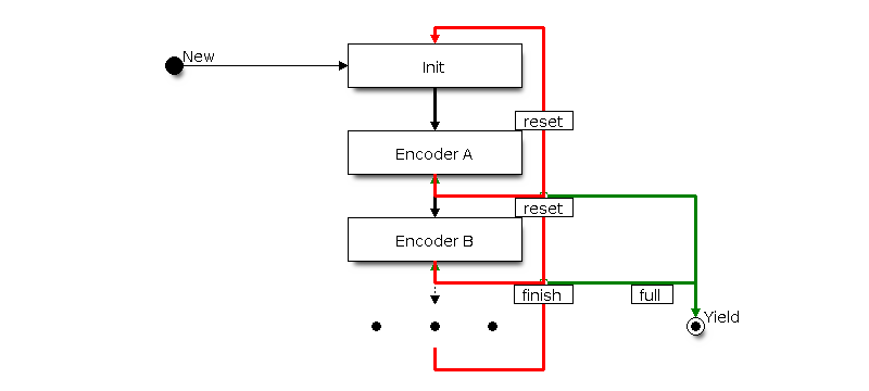
RMT Encoder Chain
Customize RMT Encoder for NEC Protocol
In this section, we will demonstrate on how to write an NEC encoder. The NEC IR protocol uses pulse distance encoding of the message bits. Each pulse burst is 562.5µs in length, logical bits are transmitted as follows. It is worth mentioning, the bytes of data bits are sent least significant bit first.
Logical
0: a 562.5µs pulse burst followed by a 562.5µs space, with a total transmit time of 1.125msLogical
1: a 562.5µs pulse burst followed by a 1.6875ms space, with a total transmit time of 2.25ms
When a key is pressed on the remote controller, the message transmitted consists of the following, in order:
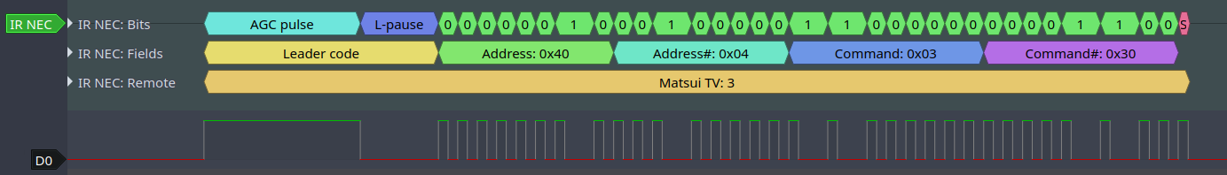
IR NEC Frame
9ms leading pulse burst (also called the “AGC pulse”)
4.5ms space
8-bit address for the receiving device
8-bit logical inverse of the address
8-bit command
8-bit logical inverse of the command
a final 562.5µs pulse burst to signify the end of message transmission
Then we can construct the NEC rmt_encoder_t::encode function in the same order, for example:
// IR NEC scan code representation
typedef struct {
    uint16_t address;
    uint16_t command;
} ir_nec_scan_code_t;

// construct a encoder by combining primitive encoders
typedef struct {
    rmt_encoder_t base;           // the base "class", declares the standard encoder interface
    rmt_encoder_t *copy_encoder;  // use the copy_encoder to encode the leading and ending pulse
    rmt_encoder_t *bytes_encoder; // use the bytes_encoder to encode the address and command data
    rmt_symbol_word_t nec_leading_symbol; // NEC leading code with RMT representation
    rmt_symbol_word_t nec_ending_symbol;  // NEC ending code with RMT representation
    int state; // record the current encoding state (i.e. we're in which encoding phase)
} rmt_ir_nec_encoder_t;

static size_t rmt_encode_ir_nec(rmt_encoder_t *encoder, rmt_channel_handle_t channel, const void *primary_data, size_t data_size, rmt_encode_state_t *ret_state)
{
    rmt_ir_nec_encoder_t *nec_encoder = __containerof(encoder, rmt_ir_nec_encoder_t, base);
    rmt_encode_state_t session_state = 0;
    rmt_encode_state_t state = 0;
    size_t encoded_symbols = 0;
    ir_nec_scan_code_t *scan_code = (ir_nec_scan_code_t *)primary_data;
    rmt_encoder_handle_t copy_encoder = nec_encoder->copy_encoder;
    rmt_encoder_handle_t bytes_encoder = nec_encoder->bytes_encoder;
    switch (nec_encoder->state) {
    case 0: // send leading code
        encoded_symbols += copy_encoder->encode(copy_encoder, channel, &nec_encoder->nec_leading_symbol,
                                                sizeof(rmt_symbol_word_t), &session_state);
        if (session_state & RMT_ENCODING_COMPLETE) {
            nec_encoder->state = 1; // we can only switch to next state when current encoder finished
        }
        if (session_state & RMT_ENCODING_MEM_FULL) {
            state |= RMT_ENCODING_MEM_FULL;
            goto out; // yield if there's no free space to put other encoding artifacts
        }
    // fall-through
    case 1: // send address
        encoded_symbols += bytes_encoder->encode(bytes_encoder, channel, &scan_code->address, sizeof(uint16_t), &session_state);
        if (session_state & RMT_ENCODING_COMPLETE) {
            nec_encoder->state = 2; // we can only switch to next state when current encoder finished
        }
        if (session_state & RMT_ENCODING_MEM_FULL) {
            state |= RMT_ENCODING_MEM_FULL;
            goto out; // yield if there's no free space to put other encoding artifacts
        }
    // fall-through
    case 2: // send command
        encoded_symbols += bytes_encoder->encode(bytes_encoder, channel, &scan_code->command, sizeof(uint16_t), &session_state);
        if (session_state & RMT_ENCODING_COMPLETE) {
            nec_encoder->state = 3; // we can only switch to next state when current encoder finished
        }
        if (session_state & RMT_ENCODING_MEM_FULL) {
            state |= RMT_ENCODING_MEM_FULL;
            goto out; // yield if there's no free space to put other encoding artifacts
        }
    // fall-through
    case 3: // send ending code
        encoded_symbols += copy_encoder->encode(copy_encoder, channel, &nec_encoder->nec_ending_symbol,
                                                sizeof(rmt_symbol_word_t), &session_state);
        if (session_state & RMT_ENCODING_COMPLETE) {
            nec_encoder->state = 0; // back to the initial encoding session
            state |= RMT_ENCODING_COMPLETE; // telling the caller the NEC encoding has finished
        }
        if (session_state & RMT_ENCODING_MEM_FULL) {
            state |= RMT_ENCODING_MEM_FULL;
            goto out; // yield if there's no free space to put other encoding artifacts
        }
    }
out:
    *ret_state = state;
    return encoded_symbols;
}
A full sample code can be found in peripherals/rmt/ir_nec_transceiver. In the above snippet, we use a switch-case plus several goto statements to implement a state machine . With this pattern, user can construct a lot more complex IR protocols.
Power Management
When power management is enabled (i.e. CONFIG_PM_ENABLE is on), the system will adjust the APB frequency before going into light sleep, thus potentially changing the resolution of RMT internal counter.
However, the driver can prevent the system from changing APB frequency by acquiring a power management lock of type ESP_PM_APB_FREQ_MAX. Whenever user creates an RMT channel that has selected RMT_CLK_SRC_APB as the clock source, the driver will guarantee that the power management lock is acquired after the channel enabled by rmt_enable(). Likewise, the driver releases the lock after rmt_disable() is called for the same channel. This also reveals that the rmt_enable() and rmt_disable() should appear in pairs.
If the channel clock source is selected to others like RMT_CLK_SRC_XTAL, then the driver won’t install power management lock for it, which is more suitable for a low power application as long as the source clock can still provide sufficient resolution.
IRAM Safe
By default, the RMT interrupt will be deferred when the Cache is disabled for reasons like writing/erasing the main Flash. Thus the transaction done interrupt will not get executed in time, which is not expected in a real-time application. What’s worse, when the RMT transaction relies on ping-pong interrupt to successively encode or copy RMT symbols, such delayed response can lead to an unpredictable result.
There’s a Kconfig option CONFIG_RMT_ISR_IRAM_SAFE that will:
Enable the interrupt being serviced even when cache is disabled
Place all functions that used by the ISR into IRAM 2
Place driver object into DRAM (in case it’s mapped to PSRAM by accident)
This Kconfig option will allow the interrupt to run while the cache is disabled but will come at the cost of increased IRAM consumption.
Thread Safety
The factory function rmt_new_tx_channel(), rmt_new_rx_channel() and rmt_new_sync_manager() are guaranteed to be thread safe by the driver, which means, user can call them from different RTOS tasks without protection by extra locks.
Other functions that take the rmt_channel_handle_t and rmt_sync_manager_handle_t as the first positional parameter, are not thread safe. which means the user should avoid calling them from multiple tasks.
Kconfig Options
CONFIG_RMT_ISR_IRAM_SAFE controls whether the default ISR handler can work when cache is disabled, see also IRAM Safe for more information.
CONFIG_RMT_ENABLE_DEBUG_LOG is used to enabled the debug log at the cost of increased firmware binary size.
Application Examples
RMT based RGB LED strip customized encoder: peripherals/rmt/led_strip
RMT IR NEC protocol encoding and decoding: peripherals/rmt/ir_nec_transceiver
RMT transactions in queue: peripherals/rmt/musical_buzzer
RMT based stepper motor with S-curve algorithm: : peripherals/rmt/stepper_motor
RMT infinite loop for driving DShot ESC: peripherals/rmt/dshot_esc
RMT simulate 1-wire protocol (take DS18B20 as example): peripherals/rmt/onewire_ds18b20
API Reference
Header File
Functions
-
esp_err_t rmt_new_tx_channel(const rmt_tx_channel_config_t *config, rmt_channel_handle_t *ret_chan)
Create a RMT TX channel.
- Parameters
config – [in] TX channel configurations
ret_chan – [out] Returned generic RMT channel handle
- Returns
ESP_OK: Create RMT TX channel successfully
ESP_ERR_INVALID_ARG: Create RMT TX channel failed because of invalid argument
ESP_ERR_NO_MEM: Create RMT TX channel failed because out of memory
ESP_ERR_NOT_FOUND: Create RMT TX channel failed because all RMT channels are used up and no more free one
ESP_ERR_NOT_SUPPORTED: Create RMT TX channel failed because some feature is not supported by hardware, e.g. DMA feature is not supported by hardware
ESP_FAIL: Create RMT TX channel failed because of other error
-
esp_err_t rmt_transmit(rmt_channel_handle_t tx_channel, rmt_encoder_handle_t encoder, const void *payload, size_t payload_bytes, const rmt_transmit_config_t *config)
Transmit data by RMT TX channel.
Note
This function will construct a transaction descriptor and push to a queue. The transaction will not start immediately until it’s dispatched in the ISR. If there’re too many transactions pending in the queue, this function will block until the queue has free space.
Note
The data to be transmitted will be encoded into RMT symbols by the specific
encoder.- Parameters
tx_channel – [in] RMT TX channel that created by
rmt_new_tx_channel()encoder – [in] RMT encoder that created by various factory APIs like
rmt_new_bytes_encoder()payload – [in] The raw data to be encoded into RMT symbols
payload_bytes – [in] Size of the
payloadin bytesconfig – [in] Transmission specific configuration
- Returns
ESP_OK: Transmit data successfully
ESP_ERR_INVALID_ARG: Transmit data failed because of invalid argument
ESP_ERR_INVALID_STATE: Transmit data failed because channel is not enabled
ESP_ERR_NOT_SUPPORTED: Transmit data failed because some feature is not supported by hardware, e.g. unsupported loop count
ESP_FAIL: Transmit data failed because of other error
-
esp_err_t rmt_tx_wait_all_done(rmt_channel_handle_t tx_channel, int timeout_ms)
Wait for all pending TX transactions done.
Note
This function will block forever if the pending transaction can’t be finished within a limited time (e.g. an infinite loop transaction). See also
rmt_disable()for how to terminate a working channel.- Parameters
tx_channel – [in] RMT TX channel that created by
rmt_new_tx_channel()timeout_ms – [in] Wait timeout, in ms. Specially, -1 means to wait forever.
- Returns
ESP_OK: Flush transactions successfully
ESP_ERR_INVALID_ARG: Flush transactions failed because of invalid argument
ESP_ERR_TIMEOUT: Flush transactions failed because of timeout
ESP_FAIL: Flush transactions failed because of other error
-
esp_err_t rmt_tx_register_event_callbacks(rmt_channel_handle_t tx_channel, const rmt_tx_event_callbacks_t *cbs, void *user_data)
Set event callbacks for RMT TX channel.
Note
User can deregister a previously registered callback by calling this function and setting the callback member in the
cbsstructure to NULL.Note
When CONFIG_RMT_ISR_IRAM_SAFE is enabled, the callback itself and functions called by it should be placed in IRAM. The variables used in the function should be in the SRAM as well. The
user_datashould also reside in SRAM.- Parameters
tx_channel – [in] RMT generic channel that created by
rmt_new_tx_channel()cbs – [in] Group of callback functions
user_data – [in] User data, which will be passed to callback functions directly
- Returns
ESP_OK: Set event callbacks successfully
ESP_ERR_INVALID_ARG: Set event callbacks failed because of invalid argument
ESP_FAIL: Set event callbacks failed because of other error
-
esp_err_t rmt_new_sync_manager(const rmt_sync_manager_config_t *config, rmt_sync_manager_handle_t *ret_synchro)
Create a synchronization manager for multiple TX channels, so that the managed channel can start transmitting at the same time.
Note
All the channels to be managed should be enabled by
rmt_enable()before put them into sync manager.- Parameters
config – [in] Synchronization manager configuration
ret_synchro – [out] Returned synchronization manager handle
- Returns
ESP_OK: Create sync manager successfully
ESP_ERR_INVALID_ARG: Create sync manager failed because of invalid argument
ESP_ERR_NOT_SUPPORTED: Create sync manager failed because it is not supported by hardware
ESP_ERR_INVALID_STATE: Create sync manager failed because not all channels are enabled
ESP_ERR_NO_MEM: Create sync manager failed because out of memory
ESP_ERR_NOT_FOUND: Create sync manager failed because all sync controllers are used up and no more free one
ESP_FAIL: Create sync manager failed because of other error
-
esp_err_t rmt_del_sync_manager(rmt_sync_manager_handle_t synchro)
Delete synchronization manager.
- Parameters
synchro – [in] Synchronization manager handle returned from
rmt_new_sync_manager()- Returns
ESP_OK: Delete the synchronization manager successfully
ESP_ERR_INVALID_ARG: Delete the synchronization manager failed because of invalid argument
ESP_FAIL: Delete the synchronization manager failed because of other error
-
esp_err_t rmt_sync_reset(rmt_sync_manager_handle_t synchro)
Reset synchronization manager.
- Parameters
synchro – [in] Synchronization manager handle returned from
rmt_new_sync_manager()- Returns
ESP_OK: Reset the synchronization manager successfully
ESP_ERR_INVALID_ARG: Reset the synchronization manager failed because of invalid argument
ESP_FAIL: Reset the synchronization manager failed because of other error
Structures
-
struct rmt_tx_event_callbacks_t
Group of RMT TX callbacks.
Note
The callbacks are all running under ISR environment
Note
When CONFIG_RMT_ISR_IRAM_SAFE is enabled, the callback itself and functions called by it should be placed in IRAM. The variables used in the function should be in the SRAM as well.
Public Members
-
rmt_tx_done_callback_t on_trans_done
Event callback, invoked when transmission is finished
-
rmt_tx_done_callback_t on_trans_done
-
struct rmt_tx_channel_config_t
RMT TX channel specific configuration.
Public Members
-
int gpio_num
GPIO number used by RMT TX channel. Set to -1 if unused
-
rmt_clock_source_t clk_src
Clock source of RMT TX channel, channels in the same group must use the same clock source
-
uint32_t resolution_hz
Channel clock resolution, in Hz
-
size_t mem_block_symbols
Size of memory block, in number of
rmt_symbol_word_t, must be an even
-
size_t trans_queue_depth
Depth of internal transfer queue, increase this value can support more transfers pending in the background
-
uint32_t invert_out
Whether to invert the RMT channel signal before output to GPIO pad
-
uint32_t with_dma
If set, the driver will allocate an RMT channel with DMA capability
-
uint32_t io_loop_back
The signal output from the GPIO will be fed to the input path as well
-
uint32_t io_od_mode
Configure the GPIO as open-drain mode
-
struct rmt_tx_channel_config_t::[anonymous] flags
TX channel config flags
-
int gpio_num
-
struct rmt_transmit_config_t
RMT transmit specific configuration.
Public Members
-
int loop_count
Specify the times of transmission in a loop, -1 means transmitting in an infinite loop
-
uint32_t eot_level
Set the output level for the “End Of Transmission”
-
struct rmt_transmit_config_t::[anonymous] flags
Transmit config flags
-
int loop_count
-
struct rmt_sync_manager_config_t
Synchronous manager configuration.
Public Members
-
const rmt_channel_handle_t *tx_channel_array
Array of TX channels that are about to be managed by a synchronous controller
-
size_t array_size
Size of the
tx_channel_array
-
const rmt_channel_handle_t *tx_channel_array
Header File
Functions
-
esp_err_t rmt_new_rx_channel(const rmt_rx_channel_config_t *config, rmt_channel_handle_t *ret_chan)
Create a RMT RX channel.
- Parameters
config – [in] RX channel configurations
ret_chan – [out] Returned generic RMT channel handle
- Returns
ESP_OK: Create RMT RX channel successfully
ESP_ERR_INVALID_ARG: Create RMT RX channel failed because of invalid argument
ESP_ERR_NO_MEM: Create RMT RX channel failed because out of memory
ESP_ERR_NOT_FOUND: Create RMT RX channel failed because all RMT channels are used up and no more free one
ESP_ERR_NOT_SUPPORTED: Create RMT RX channel failed because some feature is not supported by hardware, e.g. DMA feature is not supported by hardware
ESP_FAIL: Create RMT RX channel failed because of other error
-
esp_err_t rmt_receive(rmt_channel_handle_t rx_channel, void *buffer, size_t buffer_size, const rmt_receive_config_t *config)
Initiate a receive job for RMT RX channel.
Note
This function is non-blocking, it initiates a new receive job and then returns. User should check the received data from the
on_recv_donecallback that registered byrmt_rx_register_event_callbacks().- Parameters
rx_channel – [in] RMT RX channel that created by
rmt_new_rx_channel()buffer – [in] The buffer to store the received RMT symbols
buffer_size – [in] size of the
buffer, in bytesconfig – [in] Receive specific configurations
- Returns
ESP_OK: Initiate receive job successfully
ESP_ERR_INVALID_ARG: Initiate receive job failed because of invalid argument
ESP_ERR_INVALID_STATE: Initiate receive job failed because channel is not enabled
ESP_FAIL: Initiate receive job failed because of other error
-
esp_err_t rmt_rx_register_event_callbacks(rmt_channel_handle_t rx_channel, const rmt_rx_event_callbacks_t *cbs, void *user_data)
Set callbacks for RMT RX channel.
Note
User can deregister a previously registered callback by calling this function and setting the callback member in the
cbsstructure to NULL.Note
When CONFIG_RMT_ISR_IRAM_SAFE is enabled, the callback itself and functions called by it should be placed in IRAM. The variables used in the function should be in the SRAM as well. The
user_datashould also reside in SRAM.- Parameters
rx_channel – [in] RMT generic channel that created by
rmt_new_rx_channel()cbs – [in] Group of callback functions
user_data – [in] User data, which will be passed to callback functions directly
- Returns
ESP_OK: Set event callbacks successfully
ESP_ERR_INVALID_ARG: Set event callbacks failed because of invalid argument
ESP_FAIL: Set event callbacks failed because of other error
Structures
-
struct rmt_rx_event_callbacks_t
Group of RMT RX callbacks.
Note
The callbacks are all running under ISR environment
Note
When CONFIG_RMT_ISR_IRAM_SAFE is enabled, the callback itself and functions called by it should be placed in IRAM. The variables used in the function should be in the SRAM as well.
Public Members
-
rmt_rx_done_callback_t on_recv_done
Event callback, invoked when one RMT channel receiving transaction completes
-
rmt_rx_done_callback_t on_recv_done
-
struct rmt_rx_channel_config_t
RMT RX channel specific configuration.
Public Members
-
int gpio_num
GPIO number used by RMT RX channel. Set to -1 if unused
-
rmt_clock_source_t clk_src
Clock source of RMT RX channel, channels in the same group must use the same clock source
-
uint32_t resolution_hz
Channel clock resolution, in Hz
-
size_t mem_block_symbols
Size of memory block, in number of
rmt_symbol_word_t, must be an even
-
uint32_t invert_in
Whether to invert the incoming RMT channel signal
-
uint32_t with_dma
If set, the driver will allocate an RMT channel with DMA capability
-
uint32_t io_loop_back
For debug/test, the signal output from the GPIO will be fed to the input path as well
-
struct rmt_rx_channel_config_t::[anonymous] flags
RX channel config flags
-
int gpio_num
-
struct rmt_receive_config_t
RMT receive specific configuration.
Header File
Functions
-
esp_err_t rmt_del_channel(rmt_channel_handle_t channel)
Delete an RMT channel.
- Parameters
channel – [in] RMT generic channel that created by
rmt_new_tx_channel()orrmt_new_rx_channel()- Returns
ESP_OK: Delete RMT channel successfully
ESP_ERR_INVALID_ARG: Delete RMT channel failed because of invalid argument
ESP_ERR_INVALID_STATE: Delete RMT channel failed because it is still in working
ESP_FAIL: Delete RMT channel failed because of other error
-
esp_err_t rmt_apply_carrier(rmt_channel_handle_t channel, const rmt_carrier_config_t *config)
Apply modulation feature for TX channel or demodulation feature for RX channel.
- Parameters
channel – [in] RMT generic channel that created by
rmt_new_tx_channel()orrmt_new_rx_channel()config – [in] Carrier configuration. Specially, a NULL config means to disable the carrier modulation or demodulation feature
- Returns
ESP_OK: Apply carrier configuration successfully
ESP_ERR_INVALID_ARG: Apply carrier configuration failed because of invalid argument
ESP_FAIL: Apply carrier configuration failed because of other error
-
esp_err_t rmt_enable(rmt_channel_handle_t channel)
Enable the RMT channel.
Note
This function will acquire a PM lock that might be installed during channel allocation
- Parameters
channel – [in] RMT generic channel that created by
rmt_new_tx_channel()orrmt_new_rx_channel()- Returns
ESP_OK: Enable RMT channel successfully
ESP_ERR_INVALID_ARG: Enable RMT channel failed because of invalid argument
ESP_ERR_INVALID_STATE: Enable RMT channel failed because it’s enabled already
ESP_FAIL: Enable RMT channel failed because of other error
-
esp_err_t rmt_disable(rmt_channel_handle_t channel)
Disable the RMT channel.
Note
This function will release a PM lock that might be installed during channel allocation
- Parameters
channel – [in] RMT generic channel that created by
rmt_new_tx_channel()orrmt_new_rx_channel()- Returns
ESP_OK: Disable RMT channel successfully
ESP_ERR_INVALID_ARG: Disable RMT channel failed because of invalid argument
ESP_ERR_INVALID_STATE: Disable RMT channel failed because it’s not enabled yet
ESP_FAIL: Disable RMT channel failed because of other error
Structures
-
struct rmt_carrier_config_t
RMT carrier wave configuration (for either modulation or demodulation)
Public Members
-
uint32_t frequency_hz
Carrier wave frequency, in Hz, 0 means disabling the carrier
-
float duty_cycle
Carrier wave duty cycle (0~100%)
-
uint32_t polarity_active_low
Specify the polarity of carrier, by default it’s modulated to base signal’s high level
-
uint32_t always_on
If set, the carrier can always exist even there’s not transfer undergoing
-
struct rmt_carrier_config_t::[anonymous] flags
Carrier config flags
-
uint32_t frequency_hz
Header File
Functions
-
esp_err_t rmt_new_bytes_encoder(const rmt_bytes_encoder_config_t *config, rmt_encoder_handle_t *ret_encoder)
Create RMT bytes encoder, which can encode byte stream into RMT symbols.
- Parameters
config – [in] Bytes encoder configuration
ret_encoder – [out] Returned encoder handle
- Returns
ESP_OK: Create RMT bytes encoder successfully
ESP_ERR_INVALID_ARG: Create RMT bytes encoder failed because of invalid argument
ESP_ERR_NO_MEM: Create RMT bytes encoder failed because out of memory
ESP_FAIL: Create RMT bytes encoder failed because of other error
-
esp_err_t rmt_new_copy_encoder(const rmt_copy_encoder_config_t *config, rmt_encoder_handle_t *ret_encoder)
Create RMT copy encoder, which copies the given RMT symbols into RMT memory.
- Parameters
config – [in] Copy encoder configuration
ret_encoder – [out] Returned encoder handle
- Returns
ESP_OK: Create RMT copy encoder successfully
ESP_ERR_INVALID_ARG: Create RMT copy encoder failed because of invalid argument
ESP_ERR_NO_MEM: Create RMT copy encoder failed because out of memory
ESP_FAIL: Create RMT copy encoder failed because of other error
-
esp_err_t rmt_del_encoder(rmt_encoder_handle_t encoder)
Delete RMT encoder.
- Parameters
encoder – [in] RMT encoder handle, created by e.g
rmt_new_bytes_encoder()- Returns
ESP_OK: Delete RMT encoder successfully
ESP_ERR_INVALID_ARG: Delete RMT encoder failed because of invalid argument
ESP_FAIL: Delete RMT encoder failed because of other error
-
esp_err_t rmt_encoder_reset(rmt_encoder_handle_t encoder)
Reset RMT encoder.
- Parameters
encoder – [in] RMT encoder handle, created by e.g
rmt_new_bytes_encoder()- Returns
ESP_OK: Reset RMT encoder successfully
ESP_ERR_INVALID_ARG: Reset RMT encoder failed because of invalid argument
ESP_FAIL: Reset RMT encoder failed because of other error
Structures
-
struct rmt_encoder_t
Interface of RMT encoder.
Public Members
-
size_t (*encode)(rmt_encoder_t *encoder, rmt_channel_handle_t tx_channel, const void *primary_data, size_t data_size, rmt_encode_state_t *ret_state)
Encode the user data into RMT symbols and write into RMT memory.
Note
The encoding function will also be called from an ISR context, thus the function must not call any blocking API.
Note
It’s recommended to put this function implementation in the IRAM, to achieve a high performance and less interrupt latency.
- Param encoder
[in] Encoder handle
- Param tx_channel
[in] RMT TX channel handle, returned from
rmt_new_tx_channel()- Param primary_data
[in] App data to be encoded into RMT symbols
- Param data_size
[in] Size of primary_data, in bytes
- Param ret_state
[out] Returned current encoder’s state
- Return
Number of RMT symbols that the primary data has been encoded into
-
esp_err_t (*reset)(rmt_encoder_t *encoder)
Reset encoding state.
- Param encoder
[in] Encoder handle
- Return
ESP_OK: reset encoder successfully
ESP_FAIL: reset encoder failed
-
esp_err_t (*del)(rmt_encoder_t *encoder)
Delete encoder object.
- Param encoder
[in] Encoder handle
- Return
ESP_OK: delete encoder successfully
ESP_FAIL: delete encoder failed
-
size_t (*encode)(rmt_encoder_t *encoder, rmt_channel_handle_t tx_channel, const void *primary_data, size_t data_size, rmt_encode_state_t *ret_state)
-
struct rmt_bytes_encoder_config_t
Bytes encoder configuration.
Public Members
-
rmt_symbol_word_t bit0
How to represent BIT0 in RMT symbol
-
rmt_symbol_word_t bit1
How to represent BIT1 in RMT symbol
-
uint32_t msb_first
Whether to encode MSB bit first
-
struct rmt_bytes_encoder_config_t::[anonymous] flags
Encoder config flag
-
rmt_symbol_word_t bit0
-
struct rmt_copy_encoder_config_t
Copy encoder configuration.
Type Definitions
-
typedef struct rmt_encoder_t rmt_encoder_t
Type of RMT encoder.
Enumerations
Header File
Structures
-
struct rmt_tx_done_event_data_t
Type of RMT TX done event data.
Public Members
-
size_t num_symbols
The number of transmitted RMT symbols (only one round is counted if it’s a loop transmission)
-
size_t num_symbols
-
struct rmt_rx_done_event_data_t
Type of RMT RX done event data.
Public Members
-
rmt_symbol_word_t *received_symbols
Point to the received RMT symbols
-
size_t num_symbols
The number of received RMT symbols
-
rmt_symbol_word_t *received_symbols
Type Definitions
-
typedef struct rmt_channel_t *rmt_channel_handle_t
Type of RMT channel handle.
-
typedef struct rmt_sync_manager_t *rmt_sync_manager_handle_t
Type of RMT synchronization manager handle.
-
typedef struct rmt_encoder_t *rmt_encoder_handle_t
Type of RMT encoder handle.
-
typedef bool (*rmt_tx_done_callback_t)(rmt_channel_handle_t tx_chan, const rmt_tx_done_event_data_t *edata, void *user_ctx)
Prototype of RMT event callback.
- Param tx_chan
[in] RMT channel handle, created from
rmt_new_tx_channel()- Param edata
[in] Point to RMT event data. The lifecycle of this pointer memory is inside this function, user should copy it into static memory if used outside this funcion.
- Param user_ctx
[in] User registered context, passed from
rmt_tx_register_event_callbacks()- Return
Whether a high priority task has been waken up by this callback function
-
typedef bool (*rmt_rx_done_callback_t)(rmt_channel_handle_t rx_chan, const rmt_rx_done_event_data_t *edata, void *user_ctx)
Prototype of RMT event callback.
- Param rx_chan
[in] RMT channel handle, created from
rmt_new_rx_channel()- Param edata
[in] Point to RMT event data. The lifecycle of this pointer memory is inside this function, user should copy it into static memory if used outside this funcion.
- Param user_ctx
[in] User registered context, passed from
rmt_rx_register_event_callbacks()- Return
Whether a high priority task has been waken up by this function
Header File
Unions
-
union rmt_symbol_word_t
- #include <rmt_types.h>
The layout of RMT symbol stored in memory, which is decided by the hardware design.
Public Members
-
unsigned int duration0
Duration of level0
-
unsigned int level0
Level of the first part
-
unsigned int duration1
Duration of level1
-
unsigned int level1
Level of the second part
-
struct rmt_symbol_word_t::[anonymous] [anonymous]
-
unsigned int val
Equivalent unsigned value for the RMT symbol
-
unsigned int duration0
Type Definitions
-
typedef soc_periph_rmt_clk_src_t rmt_clock_source_t
RMT group clock source.
Note
User should select the clock source based on the power and resolution requirement
- 1
Different ESP chip series might have different number of RMT channels. Please refer to the [TRM] for details. The driver won’t forbid you from applying for more RMT channels, but it will return error when there’s no hardware resources available. Please always check the return value when doing Resource Allocation.
- 2
Callback function (e.g.
rmt_tx_event_callbacks_t::on_trans_done) and the functions invoked by itself should also reside in IRAM, users need to take care of this by themselves.