I2S
简介
I2S(Inter-IC Sound,集成电路内置音频总线)是一种同步串行通信协议,通常用于在两个数字音频设备之间传输音频数据。
ESP32 包含 2 个 I2S 外设。通过配置这些外设,可以借助 I2S 驱动来输入和输出采样数据。
标准 模式下的 I2S 总线包含以下几条线路:
MCLK:主时钟线。该信号线可选,具体取决于从机,主要用于向 I2S 从机提供参考时钟。
BCLK:位时钟线。用于数据线的位时钟。
WS:字(声道)选择线。通常用于识别声道(除 PDM 模式外)。
DIN/DOUT:串行数据输入/输出线。如果 DIN 和 DOUT 被配置到相同的 GPIO,数据将在内部回环。
PDM 通信模式下的 I2S 总线包含以下几条线路:
CLK:PDM 时钟线。
DIN/DOUT:串行数据输入/输出线。
每个 I2S 控制器都具备以下功能,可由 I2S 驱动进行配置:
可用作系统主机或从机
可用作发射器或接收器
DMA 控制器支持流数据采样,CPU 无需单独复制每个采样数据
每个控制器都支持 RX 或 TX 单工通信。由于 RX 与 TX 通道共用一个时钟,因此只有在两者拥有相同配置时,才可以实现全双工通信。
I2S 时钟
时钟源
i2s_clock_src_t::I2S_CLK_SRC_DEFAULT:默认 PLL 时钟。i2s_clock_src_t::I2S_CLK_SRC_APLL:音频 PLL 时钟,在高采样率应用中比I2S_CLK_SRC_PLL_160M更精确。其频率可根据采样率进行配置,但如果 APLL 已经被 EMAC 或其他通道占用,则无法更改 APLL 频率,驱动程序将尝试在原有 APLL 频率下工作。如果原有 APLL 频率无法满足 I2S 的需求,时钟配置将失败。
时钟术语
采样率:单声道每秒采样数据数量。
SCLK:源时钟频率,即时钟源的频率。
MCLK:主时钟频率,BCLK 由其产生。MCLK 信号通常作为参考时钟,用于同步 I2S 主机和从机之间的 BCLK 和 WS。
BCLK:位时钟频率,一个 BCLK 时钟周期代表数据管脚上的一个数据位。通过
i2s_std_slot_config_t::slot_bit_width配置的通道位宽即为一个声道中的 BCLK 时钟周期数量,因此一个声道中可以有 8/16/24/32 个 BCLK 时钟周期。LRCK / WS:左/右时钟或字选择时钟。在非 PDM 模式下,其频率等于采样率。
备注
通常,MCLK 应该同时是 采样率 和 BCLK 的倍数。字段 i2s_std_clk_config_t::mclk_multiple 表示 MCLK 相对于 采样率 的倍数。在大多数情况下,将其设置为 I2S_MCLK_MULTIPLE_256 即可。但如果 slot_bit_width 被设置为 I2S_SLOT_BIT_WIDTH_24BIT,为了保证 MCLK 是 BCLK 的整数倍,应该将 i2s_std_clk_config_t::mclk_multiple 设置为能被 3 整除的倍数,如 I2S_MCLK_MULTIPLE_384,否则 WS 会不精准。
I2S 通信模式
模式概览
芯片 |
I2S 标准 |
PCM-to-PDM |
PDM-to-PCM |
PDM |
TDM |
ADC/DAC |
LCD/摄像头 |
|---|---|---|---|---|---|---|---|
ESP32 |
I2S 0/1 |
I2S 0 |
I2S 0 |
I2S 0/1 |
无 |
I2S 0 |
I2S 0 |
ESP32-S2 |
I2S 0 |
无 |
无 |
无 |
无 |
无 |
I2S 0 |
ESP32-C3 |
I2S 0 |
I2S 0 |
无 |
I2S 0 |
I2S 0 |
无 |
无 |
ESP32-C6 |
I2S 0 |
I2S 0 |
无 |
I2S 0 |
I2S 0 |
无 |
无 |
ESP32-S3 |
I2S 0/1 |
I2S 0 |
I2S 0 |
I2S 0/1 |
I2S 0/1 |
无 |
无 |
ESP32-H2 |
I2S 0 |
I2S 0 |
无 |
I2S 0 |
I2S 0 |
无 |
无 |
ESP32-P4 |
I2S 0~2 |
I2S 0 |
I2S 0 |
I2S 0~2 |
I2S 0~2 |
无 |
无 |
ESP32-C5 |
I2S 0 |
I2S 0 |
无 |
I2S 0 |
I2S 0 |
无 |
无 |
ESP32-C61 |
I2S 0 |
I2S 0 |
无 |
I2S 0 |
I2S 0 |
无 |
无 |
备注
如需使用 PDM 模式,请注意不是所有 I2S 端口都支持原始 PDM 格式与 PCM 格式之间的转换,因为有些端口在 TX 方向上没有 PCM-to-PDM 数据格式转换器,或在 RX 方向上没有 PDM-to-PCM 数据格式转换器。因此,这些没有硬件格式转换器的端口只能读写原始 PDM 格式的数据。如果需要在这些端口上处理 PCM 格式的数据,则需额外采用一个软件滤波器来实现 PDM 格式和 PCM 格式之间的转换。
标准模式
标准模式中有且仅有左右两个声道,驱动中将声道称为 slot。这些声道可以支持 8/16/24/32 位宽的采样数据,声道的通信格式主要包括以下几种:
Philips 格式:数据信号与 WS 信号相比有一个位的位移。WS 信号的占空比为 50%。
MSB 格式:与 Philips 格式基本相同,但其数据没有位移。
PCM 帧同步:数据有一个位的位移,同时 WS 信号变成脉冲,持续一个 BCLK 周期。
PDM 模式
PDM(Pulse-density Modulation,脉冲密度调制)通过采样的方式将模拟信号数字化为 1 位精度的数字信号。它以脉冲密度的方式呈现模拟信号的大小,即密度越高,对应的模拟信号值越大。PDM 时序图如下所示:
PDM 格式的数据通常可以经过以下几个步骤转换为 PCM 格式:
低通滤波:用于还原模拟信号波形。一般采用 FIR 滤波器;
下采样:用于将 PDM 的过采样率降低到期望的 PCM 采样率。下采样可以用简单的抽值法实现;
高通滤波:用于去除信号的直流部分;
放大:用于调整转换后的 PCM 数据的増益。一般由转换后的 PCM 信号乘以一个系数得到最终 PCM 信号。
对于具有 PCM-to-PDM 格式转换器的 I2S 端口,可以在发送数据的时候,将 PCM 数据转换为 PDM 格式发送。
对于具有 PDM-to-PCM 格式转换器的 I2S 端口,可以再接收数据的时候,将收到的 PDM 格式的数据转换为 PCM 格式。
若硬件不具备上述的格式转换器,则 PDM 模式只能收发原始的 PDM 格式数据。需要在软件上实现 PDM-to-PCM 的转换逻辑以此得到常用的 PCM 格式数据。
备注
无论原始 PDM 格式还是 PCM 格式,PDM 模式下的一个数据单元总是 16 比特的位宽。例如,用原始 PDM 格式发送数据,那么您数组中的数据应该像这样排列:CH0 0x1234,CH1 0x5678,CH0 0x9abc,CH1 0xdef0。RX 方向同理。
PDM TX 模式原始 PDM 数据格式
要发送原始 PDM 格式的数据,您需要将 i2s_pdm_tx_slot_config_t::data_fmt 设为 i2s_pdm_data_fmt_t::I2S_PDM_DATA_FMT_RAW。另外在设置 i2s_pdm_tx_clk_config_t::sample_rate_hz 时请注意,PDM 的采样率通常在若干 MHz,典型值范围一般是 1.024MHz 到 6.144MHz 之间,您可以根据需求来设置。
而原始 PDM 数据格式下的声道配置,可以通过帮助宏 I2S_PDM_TX_SLOT_RAW_FMT_DEFAULT_CONFIG 或 :I2S_PDM_TX_SLOT_RAW_FMT_DAC_DEFAULT_CONFIG 来配置。
PDM TX 模式 PCM 数据格式(采用 PCM-to-PDM 格式转换器)
ESP32 在 I2S0 上支持 PCM-to-PDM 格式转换器,您可以通过 i2s_pdm_tx_slot_config_t::data_fmt 设为 i2s_pdm_data_fmt_t::I2S_PDM_DATA_FMT_PCM 来启用 PCM-to-PDM 格式转换器。启用后会将发送的 PCM 格式的数据转换为 PDM 格式发送。另外在设置 i2s_pdm_tx_clk_config_t::sample_rate_hz 时请注意,PCM 的采样率通常低于 100 KHz,典型值的范围一般是 16KHz 到 48KHz 之间,您可以根据需求来设置。
另外 PCM-to-PDM 转换器可配置上采样参数 i2s_pdm_tx_clk_config_t::up_sample_fp 和 i2s_pdm_tx_clk_config_t::up_sample_fs。上采样率可以通过公式 up_sample_rate = i2s_pdm_tx_clk_config_t::up_sample_fp / i2s_pdm_tx_clk_config_t::up_sample_fs 来计算。在 PDM TX 中有以下两种上采样模式,输出的 PDM 采样频率和配置的 PCM 采样频率关系如下:
固定时钟频率模式:在这种模式下,上采样率将根据采样率的变化而变化。设置
fp = 960、fs = (PCM)sample_rate / 100,则 CLK 管脚上的输出的 PDM 时钟频率将固定为128 * 48 KHz = 6.144 MHz。固定上采样率模式:在这种模式下,上采样率固定为 2。即设置
fp = 960、fs = 480,则 CLK 管脚上的 PDM 的时钟频率将为128 * sample_rate。
而 PCM 数据格式下的声道配置,您可以通过帮助宏 I2S_PDM_TX_SLOT_PCM_FMT_DEFAULT_CONFIG 和 I2S_PDM_TX_SLOT_PCM_FMT_DAC_DEFAULT_CONFIG 来配置。
PDM RX 模式原始 PDM 数据格式
要接收原始 PDM 格式的数据,您需要将 i2s_pdm_rx_slot_config_t::data_fmt 设为 i2s_pdm_data_fmt_t::I2S_PDM_DATA_FMT_RAW。另外在设置 i2s_pdm_rx_clk_config_t::sample_rate_hz 时请注意,PDM 的采样率通常在若干 MHz,典型值范围一般是 1.024MHz 到 6.144MHz 之间,您可以根据需求来设置。
而原始 PDM 数据格式下的声道配置,可以通过帮助宏 I2S_PDM_RX_SLOT_RAW_FMT_DEFAULT_CONFIG 来配置。
PDM RX 模式 PCM 数据格式(采用 PDM-to-PCM 格式转换器)
ESP32 在 I2S0 上支持 PDM-to-PCM 格式转换器,您可以通过 i2s_pdm_rx_slot_config_t::data_fmt 设为 i2s_pdm_data_fmt_t::I2S_PDM_DATA_FMT_PCM 来启用 PDM-to-PCM 格式转换器。启用后会将接收到的 PDM 格式的数据转换为 PCM 格式。另外在设置 i2s_pdm_rx_clk_config_t::sample_rate_hz 时请注意,PCM 的采样率通常低于 100 KHz,典型值的范围一般是 16KHz 到 48KHz 之间,您可以根据需求来设置。
另外 PDM-to-PCM 转换器可配置下采样参数 i2s_pdm_rx_clk_config_t::dn_sample_mode。在 PDM RX 中有以下两种下采样模式,输出的 PDM 采样频率和配置的 PCM 采样频率关系如下:
i2s_pdm_dsr_t::I2S_PDM_DSR_8S:在这种模式下,CLK 管脚的 PDM 时钟频率将为(PCM) sample_rate * 64。i2s_pdm_dsr_t::I2S_PDM_DSR_16S: 在这种模式下,CLK 管脚的 PDM 时钟频率将为(PCM) sample_rate * 128。
而 PCM 数据格式下的声道配置,可以通过帮助宏 I2S_PDM_RX_SLOT_PCM_FMT_DEFAULT_CONFIG 来配置。
LCD/摄像头模式
LCD/摄像头模式只支持在 I2S0 上通过并行总线运行。在 LCD 模式下,I2S0 应当设置为主机 TX 模式;在摄像头模式下,I2S0 应当设置为从机 RX 模式。这两种模式不是由 I2S 驱动实现的,关于 LCD 模式的实现,请参阅 I80 接口的 LCD。更多信息请参考 ESP32 技术参考手册 > I2S 控制器 (I2S) > LCD 模式 [PDF]。
ADC/DAC 模式
仅 ESP32 支持在 I2S0 上运行 ADC 和 DAC 模式。实际上,ADC 和 DAC 模式是 LCD/摄像头模式的两个子模式。I2S0 可以直接路由到内部模数转换器 (ADC) 和数模转换器 (DAC),也即 ADC 和 DAC 外设可以通过 I2S0 的 DMA 连续读取或写入数据。由于 ADC 和 DAC 并非通信模式,因此并没有在 I2S 驱动中实现。
功能概览
I2S 驱动提供以下服务:
资源管理
I2S 驱动中的资源可分为三个级别:
平台级资源:当前芯片中所有 I2S 控制器的资源。控制器级资源:一个 I2S 控制器的资源。通道级资源:一个 I2S 控制器 TX 或 RX 通道的资源。
公开的 API 都是通道级别的 API,通道句柄 i2s_chan_handle_t 可以帮助用户管理特定通道下的资源,而无需考虑其他两个级别的资源。高级别资源为私有资源,由驱动自动管理。用户可以调用 i2s_new_channel() 来分配通道句柄,或调用 i2s_del_channel() 来删除该句柄。
电源管理
电源管理启用(即开启 CONFIG_PM_ENABLE)时,系统将在进入 Light-sleep 前调整或停止 I2S 时钟源,这可能会影响 I2S 信号,从而导致传输或接收的数据无效。
I2S 驱动可以获取电源管理锁,从而防止系统设置更改或时钟源被禁用。时钟源为 APB 时,锁的类型将被设置为 esp_pm_lock_type_t::ESP_PM_APB_FREQ_MAX。时钟源为 APLL(若支持)时,锁的类型将被设置为 esp_pm_lock_type_t::ESP_PM_NO_LIGHT_SLEEP。用户通过 I2S 读写时(即调用 i2s_channel_read() 或 i2s_channel_write()),驱动程序将获取电源管理锁,并在读写完成后释放锁。
有限状态机
I2S 通道有三种状态,分别为 registered(已注册)、 ready(准备就绪) 和 running(运行中),它们的关系如下图所示:
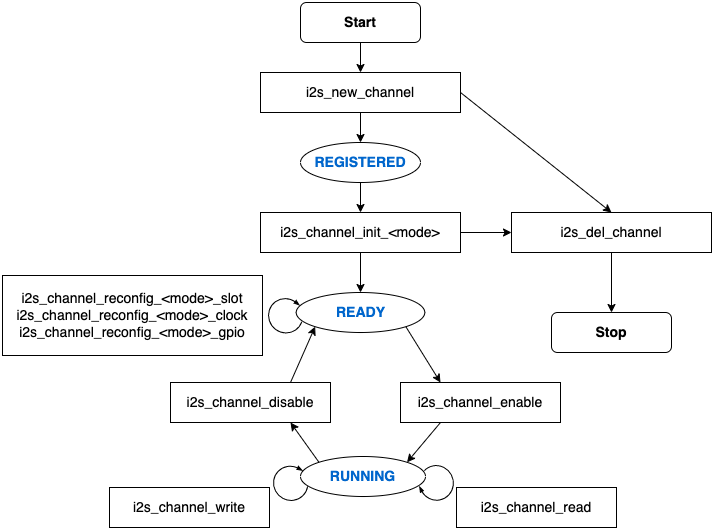
I2S 有限状态机
图中的 <mode> 可用相应的 I2S 通信模式来代替,如 std 代表标准的双声道模式。更多关于通信模式的信息,请参考 I2S 通信模式 小节。
数据传输
I2S 的数据传输(包括数据发送和接收)由 DMA 实现。在传输数据之前,请调用 i2s_channel_enable() 来启用特定的通道。发送或接收的数据达到 DMA 缓冲区的大小时,将触发 I2S_OUT_EOF 或 I2S_IN_SUC_EOF 中断。注意,DMA 缓冲区的大小不等于 i2s_chan_config_t::dma_frame_num,这里的一帧是指一个 WS 周期内的所有采样数据。因此, dma_buffer_size = dma_frame_num * slot_num * slot_bit_width / 8。传输数据时,可以调用 i2s_channel_write() 来输入数据,并把数据从源缓冲区复制到 DMA TX 缓冲区等待传输完成。此过程将重复进行,直到发送的字节数达到配置的大小。接收数据时,用户可以调用函数 i2s_channel_read() 来等待接收包含 DMA 缓冲区地址的消息队列,从而将数据从 DMA RX 缓冲区复制到目标缓冲区。
i2s_channel_write() 和 i2s_channel_read() 都是阻塞函数,在源缓冲区的数据发送完毕前,或是整个目标缓冲区都被加载数据占用时,它们会一直保持等待状态。在等待时间达到最大阻塞时间时,返回 ESP_ERR_TIMEOUT 错误。要实现异步发送或接收数据,可以通过 i2s_channel_register_event_callback() 注册回调,随即便可在回调函数中直接访问 DMA 缓冲区,无需通过这两个阻塞函数来发送或接收数据。但请注意,该回调是一个中断回调,不要在该回调中添加复杂的逻辑、进行浮点运算或调用不可重入函数。
配置
用户可以通过调用相应函数(即 i2s_channel_init_std_mode()、 i2s_channel_init_pdm_rx_mode()、 i2s_channel_init_pdm_tx_mode() 或 i2s_channel_init_tdm_mode())将通道初始化为特定模式。如果初始化后需要更新配置,必须先调用 i2s_channel_disable() 以确保通道已经停止运行,然后再调用相应的 'reconfig' 函数,例如 i2s_channel_reconfig_std_slot()、 i2s_channel_reconfig_std_clock() 和 i2s_channel_reconfig_std_gpio()。
进阶 API
为满足高质量音频需求,驱动提供了以下进阶 API:
i2s_channel_preload_data(): 用于预加载音频数据到 I2S 内部缓存,使得 TX 通道使能后能够立即发送数据,以此降低音频初始输出延迟。i2s_channel_tune_rate(): 用于在运行时动态微调音频速率,以匹配音频数据生产者和消费者的速度,从而防止因速率不匹配导致的中间缓存数据累积或不足。
IRAM 安全
默认情况下,由于写入或擦除 flash 等原因导致 cache 被禁用时,I2S 中断将产生延迟,无法及时执行 EOF 中断。
在实时应用中,可通过启用 Kconfig 选项 CONFIG_I2S_ISR_IRAM_SAFE 来避免此种情况发生,启用后:
即使在 cache 被禁用的情况下,中断仍可继续运行。
驱动程序将存放进 DRAM 中(以防其意外映射到 PSRAM 中)。
启用该选项可以保证 cache 禁用时的中断运行,但会相应增加 IRAM 占用。
线程安全
驱动程序可保证所有公开的 I2S API 的线程安全,使用时,可以直接从不同的 RTOS 任务中调用此类 API,无需额外锁保护。注意,I2S 驱动使用 mutex 锁来保证线程安全,因此不允许在 ISR 中使用这些 API。
Kconfig 选项
CONFIG_I2S_ISR_IRAM_SAFE 控制默认 ISR 处理程序能否在禁用 cache 的情况下工作。更多信息可参考 IRAM 安全。
CONFIG_I2S_ENABLE_DEBUG_LOG 用于启用调试日志输出。启用该选项将增加固件的二进制文件大小。
应用实例
I2S 驱动例程请参考 peripherals/i2s 目录。以下为每种模式的简单用法:
标准 TX/RX 模式的应用
peripherals/i2s/i2s_codec/i2s_es8311 演示了如何在 ESP32 上使用 I2S ES8311 音频编解码器来播放音乐或回声,具有高性能和低功耗的多位 delta-sigma 音频 ADC 和 DAC,提供自定义音乐、调整麦克风增益和音量的选项。
peripherals/i2s/i2s_basic/i2s_std 演示了如何在 ESP32 上以单工或全双工模式使用 I2S 标准模式。
不同声道的通信格式可通过以下标准模式的辅助宏来生成。如上所述,在标准模式下有三种格式,辅助宏分别为:
时钟配置的辅助宏为:
请参考 标准模式 了解 STD API 的相关信息。更多细节请参考 esp_driver_i2s/include/driver/i2s_std.h。
STD TX 模式
以 16 位数据位宽为例,如果 uint16_t 写缓冲区中的数据如下所示:
数据 0 |
数据 1 |
数据 2 |
数据 3 |
数据 4 |
数据 5 |
数据 6 |
数据 7 |
... |
|---|---|---|---|---|---|---|---|---|
0x0001 |
0x0002 |
0x0003 |
0x0004 |
0x0005 |
0x0006 |
0x0007 |
0x0008 |
... |
下表展示了在不同 i2s_std_slot_config_t::slot_mode 和 i2s_std_slot_config_t::slot_mask 设置下线路上的真实数据。
数据位宽 |
声道模式 |
声道掩码 |
WS 低电平 |
WS 高电平 |
WS 低电平 |
WS 高电平 |
WS 低电平 |
WS 高电平 |
WS 低电平 |
WS 高电平 |
|---|---|---|---|---|---|---|---|---|---|---|
16 位 |
单声道 |
左 |
0x0002 |
0x0000 |
0x0001 |
0x0000 |
0x0004 |
0x0000 |
0x0003 |
0x0000 |
右 |
0x0000 |
0x0002 |
0x0000 |
0x0001 |
0x0000 |
0x0004 |
0x0000 |
0x0003 |
||
左右 |
0x0002 |
0x0002 |
0x0001 |
0x0001 |
0x0004 |
0x0004 |
0x0003 |
0x0003 |
||
立体声 |
左 |
0x0001 |
0x0001 |
0x0003 |
0x0003 |
0x0005 |
0x0005 |
0x0007 |
0x0007 |
|
右 |
0x0002 |
0x0002 |
0x0004 |
0x0004 |
0x0006 |
0x0006 |
0x0008 |
0x0008 |
||
左右 |
0x0001 |
0x0002 |
0x0003 |
0x0004 |
0x0005 |
0x0006 |
0x0007 |
0x0008 |
备注
当数据位宽为 32 位时,情况与上表类似,但当位宽为 8 位和 24 位时需要额外注意。数据位宽为 8 时,写入的缓冲区仍应使用 uint16_t (即以 2 字节对齐),并且只有高 8 位有效,低 8 位将被丢弃;数据位宽为 24 时,缓冲区应该使用 uint32_t ( 即以 4 字节对齐),并且只有高 24 位有效,低 8 位将被丢弃。
另外,在 8 位宽和 16 位宽单声道模式下,线路上的真实数据顺序会被调换。为了获取正确的数据顺序,写入缓冲区时,每两个字节需要调换一次数据顺序。
#include "driver/i2s_std.h"
#include "driver/gpio.h"

i2s_chan_handle_t tx_handle;
/* 通过辅助宏获取默认的通道配置
 * 这个辅助宏在 'i2s_common.h' 中定义,由所有 I2S 通信模式共享
 * 它可以帮助指定 I2S 角色和端口 ID */
i2s_chan_config_t chan_cfg = I2S_CHANNEL_DEFAULT_CONFIG(I2S_NUM_AUTO, I2S_ROLE_MASTER);
/* 分配新的 TX 通道并获取该通道的句柄 */
i2s_new_channel(&chan_cfg, &tx_handle, NULL);

/* 进行配置,可以通过宏生成声道配置和时钟配置
 * 这两个辅助宏在 'i2s_std.h' 中定义,只能用于 STD 模式
 * 它们可以帮助初始化或更新声道和时钟配置 */
i2s_std_config_t std_cfg = {
    .clk_cfg = I2S_STD_CLK_DEFAULT_CONFIG(48000),
    .slot_cfg = I2S_STD_MSB_SLOT_DEFAULT_CONFIG(I2S_DATA_BIT_WIDTH_32BIT, I2S_SLOT_MODE_STEREO),
    .gpio_cfg = {
        .mclk = I2S_GPIO_UNUSED,
        .bclk = GPIO_NUM_4,
        .ws = GPIO_NUM_5,
        .dout = GPIO_NUM_18,
        .din = I2S_GPIO_UNUSED,
        .invert_flags = {
            .mclk_inv = false,
            .bclk_inv = false,
            .ws_inv = false,
        },
    },
};
/* 初始化通道 */
i2s_channel_init_std_mode(tx_handle, &std_cfg);

/* 在写入数据之前,先启用 TX 通道 */
i2s_channel_enable(tx_handle);
i2s_channel_write(tx_handle, src_buf, bytes_to_write, bytes_written, ticks_to_wait);

/* 如果需要更新声道或时钟配置
 * 需要在更新前先禁用通道 */
// i2s_channel_disable(tx_handle);
// std_cfg.slot_cfg.slot_mode = I2S_SLOT_MODE_MONO; // 默认为立体声
// i2s_channel_reconfig_std_slot(tx_handle, &std_cfg.slot_cfg);
// std_cfg.clk_cfg.sample_rate_hz = 96000;
// i2s_channel_reconfig_std_clock(tx_handle, &std_cfg.clk_cfg);

/* 删除通道之前必须先禁用通道 */
i2s_channel_disable(tx_handle);
/* 如果不再需要句柄,删除该句柄以释放通道资源 */
i2s_del_channel(tx_handle);
STD RX 模式
例如,当数据位宽为 16 时,如线路上的数据如下所示:
WS 低电平 |
WS 高电平 |
WS 低电平 |
WS 高电平 |
WS 低电平 |
WS 高电平 |
WS 低电平 |
WS 高电平 |
... |
|---|---|---|---|---|---|---|---|---|
0x0001 |
0x0002 |
0x0003 |
0x0004 |
0x0005 |
0x0006 |
0x0007 |
0x0008 |
... |
不同 i2s_std_slot_config_t::slot_mode 和 i2s_std_slot_config_t::slot_mask 配置下缓冲区中收到的数据如下所示。
数据位宽 |
声道模式 |
声道掩码 |
数据 0 |
数据 1 |
数据 2 |
数据 3 |
数据 4 |
数据 5 |
数据 6 |
数据 7 |
|---|---|---|---|---|---|---|---|---|---|---|
16 位 |
单声道 |
左 |
0x0001 |
0x0000 |
0x0005 |
0x0003 |
0x0009 |
0x0007 |
0x000d |
0x000b |
右 |
0x0002 |
0x0000 |
0x0006 |
0x0004 |
0x000a |
0x0008 |
0x000e |
0x000c |
||
立体声 |
任意 |
0x0001 |
0x0002 |
0x0003 |
0x0004 |
0x0005 |
0x0006 |
0x0007 |
0x0008 |
备注
ESP32 上的接收有些复杂。首先,当数据位宽为 8 位或 24 位时,接收的数据仍将以 2 个字节或 4 个字节对齐,这意味着有效数据被放在每两个字节的高 8 位和每四个字节的高 24 位。例如,当线路上的数据是 8 位宽度的 0x5A 时,接收的数据将是 0x5A00;当数据是 0x00 005A 时,则收到 0x0000 5A00。其次,在 8 位宽和 16 位宽单声道传输中,缓冲区内每两个数据会进行一次数据翻转,因此可能需要手动将顺序回转,以获取正确的数据顺序。
#include "driver/i2s_std.h"
#include "driver/gpio.h"

i2s_chan_handle_t rx_handle;
/* 通过辅助宏获取默认的通道配置
 * 这个辅助宏在 'i2s_common.h' 中定义,由所有 I2S 通信模式共享
 * 它可以帮助指定 I2S 角色和端口 ID */
i2s_chan_config_t chan_cfg = I2S_CHANNEL_DEFAULT_CONFIG(I2S_NUM_AUTO, I2S_ROLE_MASTER);
/* 分配新的 TX 通道并获取该通道的句柄 */
i2s_new_channel(&chan_cfg, NULL, &rx_handle);

/* 进行配置,可以通过宏生成声道配置和时钟配置
 * 这两个辅助宏在 'i2s_std.h' 中定义,只能用于 STD 模式
 * 它们可以帮助初始化或更新声道和时钟配置 */
i2s_std_config_t std_cfg = {
    .clk_cfg = I2S_STD_CLK_DEFAULT_CONFIG(48000),
    .slot_cfg = I2S_STD_MSB_SLOT_DEFAULT_CONFIG(I2S_DATA_BIT_WIDTH_32BIT, I2S_SLOT_MODE_STEREO),
    .gpio_cfg = {
        .mclk = I2S_GPIO_UNUSED,
        .bclk = GPIO_NUM_4,
        .ws = GPIO_NUM_5,
        .dout = I2S_GPIO_UNUSED,
        .din = GPIO_NUM_19,
        .invert_flags = {
            .mclk_inv = false,
            .bclk_inv = false,
            .ws_inv = false,
        },
    },
};
/* 初始化通道 */
i2s_channel_init_std_mode(rx_handle, &std_cfg);

/* 在读取数据之前,先启动 RX 通道 */
i2s_channel_enable(rx_handle);
i2s_channel_read(rx_handle, desc_buf, bytes_to_read, bytes_read, ticks_to_wait);

/* 删除通道之前必须先禁用通道 */
i2s_channel_disable(rx_handle);
/* 如果不再需要句柄,删除该句柄以释放通道资源 */
i2s_del_channel(rx_handle);
PDM TX 模式的应用
peripherals/i2s/i2s_basic/i2s_pdm 演示了如何在 ESP32 上使用 PDM TX 模式,包括必要的硬件设置和配置。
针对 TX 通道的 PDM 模式,声道配置的辅助宏为:
I2S_PDM_TX_SLOT_DEFAULT_CONFIG
时钟配置的辅助宏为:
PDM TX API 的相关信息,可参考 PDM 模式。更多细节请参阅 esp_driver_i2s/include/driver/i2s_pdm.h。
PDM 数据位宽固定为 16 位。如果 int16_t 写缓冲区中的数据如下:
数据 0 |
数据 1 |
数据 2 |
数据 3 |
数据 4 |
数据 5 |
数据 6 |
数据 7 |
... |
|---|---|---|---|---|---|---|---|---|
0x0001 |
0x0002 |
0x0003 |
0x0004 |
0x0005 |
0x0006 |
0x0007 |
0x0008 |
... |
下表展示了不同 i2s_pdm_tx_slot_config_t::slot_mode 和 i2s_pdm_tx_slot_config_t::slot_mask 设置下线路上的真实数据。为方便理解,已将线路上的数据格式由 PDM 转为 PCM。
声道模式 |
声道掩码 |
左 |
右 |
左 |
右 |
左 |
右 |
左 |
右 |
|---|---|---|---|---|---|---|---|---|---|
单声道 |
左 |
0x0001 |
0x0000 |
0x0002 |
0x0000 |
0x0003 |
0x0000 |
0x0004 |
0x0000 |
右 |
0x0000 |
0x0001 |
0x0000 |
0x0002 |
0x0000 |
0x0003 |
0x0000 |
0x0004 |
|
左右 |
0x0001 |
0x0001 |
0x0002 |
0x0002 |
0x0003 |
0x0003 |
0x0004 |
0x0004 |
|
立体声 |
左 |
0x0001 |
0x0001 |
0x0003 |
0x0003 |
0x0005 |
0x0005 |
0x0007 |
0x0007 |
右 |
0x0002 |
0x0002 |
0x0004 |
0x0004 |
0x0006 |
0x0006 |
0x0008 |
0x0008 |
|
左右 |
0x0001 |
0x0002 |
0x0003 |
0x0004 |
0x0005 |
0x0006 |
0x0007 |
0x0008 |
#include "driver/i2s_pdm.h"
#include "driver/gpio.h"

/* 分配 I2S TX 通道 */
i2s_chan_config_t chan_cfg = I2S_CHANNEL_DEFAULT_CONFIG(I2S_NUM_0, I2S_ROLE_MASTER);
i2s_new_channel(&chan_cfg, &tx_handle, NULL);

/* 初始化通道为 PDM TX 模式 */
i2s_pdm_tx_config_t pdm_tx_cfg = {
    .clk_cfg = I2S_PDM_TX_CLK_DEFAULT_CONFIG(36000),
    .slot_cfg = I2S_PDM_TX_SLOT_DEFAULT_CONFIG(I2S_DATA_BIT_WIDTH_16BIT, I2S_SLOT_MODE_MONO),
    .gpio_cfg = {
        .clk = GPIO_NUM_5,
        .dout = GPIO_NUM_18,
        .invert_flags = {
            .clk_inv = false,
        },
    },
};
i2s_channel_init_pdm_tx_mode(tx_handle, &pdm_tx_cfg);

...
PDM RX 模式的应用
peripherals/i2s/i2s_recorder 演示了如何通过 I2S 外设以 PDM 数据格式用数字 MEMS 麦克风录制音频,并将其以
.wav文件格式保存到 ESP32 开发板上的 SD 卡中。peripherals/i2s/i2s_basic/i2s_pdm 演示了如何在 ESP32 上使用 PDM RX 模式,包括必要的硬件设置和配置。
针对 RX 通道的 PDM 模式,声道配置的辅助宏为:
I2S_PDM_RX_SLOT_RAW_FMT_DEFAULT_CONFIG该辅助宏为接收原始 PDM 数据格式提供了一些默认配置。
I2S_PDM_RX_SLOT_PCM_FMT_DEFAULT_CONFIG该辅助宏为接收转换后的 PCM 数据格式提供了一些默认配置。
时钟配置的辅助宏为:
PDM RX API 的相关信息,可参考 PDM 模式。更多细节请参阅 esp_driver_i2s/include/driver/i2s_pdm.h。
PDM 数据位宽固定为 16 位。如果线路上的数据如下所示。为方便理解,已将线路上的数据格式由 PDM 转为 PCM。
左 |
右 |
左 |
右 |
左 |
右 |
左 |
右 |
... |
|---|---|---|---|---|---|---|---|---|
0x0001 |
0x0002 |
0x0003 |
0x0004 |
0x0005 |
0x0006 |
0x0007 |
0x0008 |
... |
下表展示了不同 i2s_pdm_rx_slot_config_t::slot_mode 和 i2s_pdm_rx_slot_config_t::slot_mask 设置下 'int16_t' 缓冲区接收的数据。
声道模式 |
声道掩码 |
数据 0 |
数据 1 |
数据 2 |
数据 3 |
数据 4 |
数据 5 |
数据 6 |
数据 7 |
|---|---|---|---|---|---|---|---|---|---|
单声道 |
左 |
0x0001 |
0x0003 |
0x0005 |
0x0007 |
0x0009 |
0x000b |
0x000d |
0x000f |
右 |
0x0002 |
0x0004 |
0x0006 |
0x0008 |
0x000a |
0x000c |
0x000e |
0x0010 |
|
立体声 |
左右 |
0x0001 |
0x0002 |
0x0003 |
0x0004 |
0x0005 |
0x0006 |
0x0007 |
0x0008 |
#include "driver/i2s_pdm.h"
#include "driver/gpio.h"

i2s_chan_handle_t rx_handle;

/* 分配 I2S RX 通道 */
i2s_chan_config_t chan_cfg = I2S_CHANNEL_DEFAULT_CONFIG(I2S_NUM_0, I2S_ROLE_MASTER);
i2s_new_channel(&chan_cfg, NULL, &rx_handle);

/* 初始化通道为 PDM RX 模式 */
i2s_pdm_rx_config_t pdm_rx_cfg = {
    .clk_cfg = I2S_PDM_RX_CLK_DEFAULT_CONFIG(36000),
    // 若不支持 PDM 转 PCM 格式转换器,请使用原始 PDM 格式
    // .slot_cfg = I2S_PDM_RX_SLOT_RAW_FMT_DEFAULT_CONFIG(I2S_DATA_BIT_WIDTH_16BIT, I2S_SLOT_MODE_MONO),
    .slot_cfg = I2S_PDM_RX_SLOT_PCM_FMT_DEFAULT_CONFIG(I2S_DATA_BIT_WIDTH_16BIT, I2S_SLOT_MODE_MONO),
    .gpio_cfg = {
        .clk = GPIO_NUM_5,
        .din = GPIO_NUM_19,
        .invert_flags = {
            .clk_inv = false,
        },
    },
};
i2s_channel_init_pdm_rx_mode(rx_handle, &pdm_rx_cfg);

...
全双工
全双工模式可以在 I2S 端口中同时注册 TX 和 RX 通道,同时通道共享 BCLK 和 WS 信号。目前,标准 通信模式支持以下方式的全双工通信,但不支持 PDM 全双工模式,因为 PDM 模式下 TX 和 RX 通道的时钟不同。
请注意,一个句柄只能代表一个通道,因此仍然需要对 TX 和 RX 通道逐个进行声道和时钟配置。
驱动支持两种分配全双工通道的方法:
在调用
i2s_new_channel()函数时,同时分配 TX 和 RX 通道两个通道。
#include "driver/i2s_std.h"
#include "driver/gpio.h"

i2s_chan_handle_t tx_handle;
i2s_chan_handle_t rx_handle;

/* 分配两个 I2S 通道 */
i2s_chan_config_t chan_cfg = I2S_CHANNEL_DEFAULT_CONFIG(I2S_NUM_AUTO, I2S_ROLE_MASTER);
/* 同时分配给 TX 和 RX 通道,使其进入全双工模式。 */
i2s_new_channel(&chan_cfg, &tx_handle, &rx_handle);

/* 配置两个通道,因为在全双工模式下,TX 和 RX 通道必须相同。 */
i2s_std_config_t std_cfg = {
    .clk_cfg = I2S_STD_CLK_DEFAULT_CONFIG(32000),
    .slot_cfg = I2S_STD_PHILIPS_SLOT_DEFAULT_CONFIG(I2S_DATA_BIT_WIDTH_16BIT, I2S_SLOT_MODE_STEREO),
    .gpio_cfg = {
        .mclk = I2S_GPIO_UNUSED,
        .bclk = GPIO_NUM_4,
        .ws = GPIO_NUM_5,
        .dout = GPIO_NUM_18,
        .din = GPIO_NUM_19,
        .invert_flags = {
            .mclk_inv = false,
            .bclk_inv = false,
            .ws_inv = false,
        },
    },
};
i2s_channel_init_std_mode(tx_handle, &std_cfg);
i2s_channel_init_std_mode(rx_handle, &std_cfg);

i2s_channel_enable(tx_handle);
i2s_channel_enable(rx_handle);

...
调用两次
i2s_new_channel()函数分别分配 TX 和 RX 通道,但使用相同配置初始化 TX 和 RX 通道。
#include "driver/i2s_std.h"
#include "driver/gpio.h"

i2s_chan_handle_t tx_handle;
i2s_chan_handle_t rx_handle;

/* 分配两个 I2S 通道 */
i2s_chan_config_t chan_cfg = I2S_CHANNEL_DEFAULT_CONFIG(I2S_NUM_0, I2S_ROLE_MASTER);
/* 分别分配给 TX 和 RX 通道 */
ESP_ERROR_CHECK(i2s_new_channel(&chan_cfg, &tx_handle, NULL));

/* 为两个通道设置完全相同的配置,TX 和 RX 将自动组成全双工模式 */
i2s_std_config_t std_cfg = {
    .clk_cfg = I2S_STD_CLK_DEFAULT_CONFIG(32000),
    .slot_cfg = I2S_STD_PHILIPS_SLOT_DEFAULT_CONFIG(I2S_DATA_BIT_WIDTH_16BIT, I2S_SLOT_MODE_STEREO),
    .gpio_cfg = {
        .mclk = I2S_GPIO_UNUSED,
        .bclk = GPIO_NUM_4,
        .ws = GPIO_NUM_5,
        .dout = GPIO_NUM_18,
        .din = GPIO_NUM_19,
        .invert_flags = {
            .mclk_inv = false,
            .bclk_inv = false,
            .ws_inv = false,
        },
    },
};
ESP_ERROR_CHECK(i2s_channel_init_std_mode(tx_handle, &std_cfg));
ESP_ERROR_CHECK(i2s_channel_enable(tx_handle));
// ...
ESP_ERROR_CHECK(i2s_new_channel(&chan_cfg, NULL, &rx_handle));
ESP_ERROR_CHECK(i2s_channel_init_std_mode(rx_handle, &std_cfg));
ESP_ERROR_CHECK(i2s_channel_enable(rx_handle));

...
单工模式
在单工模式下分配通道句柄,应该为每个通道调用 i2s_new_channel()。在 ESP32 上,TX/RX 通道的时钟和 GPIO 管脚不是相互独立的,因此在单工模式下,TX 和 RX 通道不能共存于同一个 I2S 端口中。
#include "driver/i2s_std.h"
#include "driver/gpio.h"

i2s_chan_handle_t tx_handle;
i2s_chan_handle_t rx_handle;

i2s_chan_config_t chan_cfg = I2S_CHANNEL_DEFAULT_CONFIG(I2S_NUM_AUTO, I2S_ROLE_MASTER);
ESP_ERROR_CHECK(i2s_new_channel(&chan_cfg, &tx_handle, NULL));
i2s_std_config_t std_tx_cfg = {
    .clk_cfg = I2S_STD_CLK_DEFAULT_CONFIG(48000),
    .slot_cfg = I2S_STD_PHILIPS_SLOT_DEFAULT_CONFIG(I2S_DATA_BIT_WIDTH_16BIT, I2S_SLOT_MODE_STEREO),
    .gpio_cfg = {
        .mclk = GPIO_NUM_0,
        .bclk = GPIO_NUM_4,
        .ws = GPIO_NUM_5,
        .dout = GPIO_NUM_18,
        .din = I2S_GPIO_UNUSED,
        .invert_flags = {
            .mclk_inv = false,
            .bclk_inv = false,
            .ws_inv = false,
        },
    },
};
/* 初始化通道 */
ESP_ERROR_CHECK(i2s_channel_init_std_mode(tx_handle, &std_tx_cfg));
ESP_ERROR_CHECK(i2s_channel_enable(tx_handle));

/* 如果没有找到其他可用的 I2S 设备,RX 通道将被注册在另一个 I2S 上
 * 并返回 ESP_ERR_NOT_FOUND */
ESP_ERROR_CHECK(i2s_new_channel(&chan_cfg, NULL, &rx_handle));
i2s_std_config_t std_rx_cfg = {
    .clk_cfg = I2S_STD_CLK_DEFAULT_CONFIG(16000),
    .slot_cfg = I2S_STD_MSB_SLOT_DEFAULT_CONFIG(I2S_DATA_BIT_WIDTH_32BIT, I2S_SLOT_MODE_STEREO),
    .gpio_cfg = {
        .mclk = I2S_GPIO_UNUSED,
        .bclk = GPIO_NUM_6,
        .ws = GPIO_NUM_7,
        .dout = I2S_GPIO_UNUSED,
        .din = GPIO_NUM_19,
        .invert_flags = {
            .mclk_inv = false,
            .bclk_inv = false,
            .ws_inv = false,
        },
    },
};
ESP_ERROR_CHECK(i2s_channel_init_std_mode(rx_handle, &std_rx_cfg));
ESP_ERROR_CHECK(i2s_channel_enable(rx_handle));
应用注意事项
防止数据丢失
对于需要高频采样率的应用,数据的巨大吞吐量可能会导致数据丢失。用户可以通过注册 ISR 回调函数来接收事件队列中的数据丢失事件:
static IRAM_ATTR bool i2s_rx_queue_overflow_callback(i2s_chan_handle_t handle, i2s_event_data_t *event, void *user_ctx)
{
    // 处理 RX 队列溢出事件 ...
    return false;
}

i2s_event_callbacks_t cbs = {
    .on_recv = NULL,
    .on_recv_q_ovf = i2s_rx_queue_overflow_callback,
    .on_sent = NULL,
    .on_send_q_ovf = NULL,
};
TEST_ESP_OK(i2s_channel_register_event_callback(rx_handle, &cbs, NULL));
请按照以下步骤操作,以防止数据丢失:
确定中断间隔。通常来说,当发生数据丢失时,为减少中断次数,中断间隔应该越久越好。因此,在保证 DMA 缓冲区大小不超过最大值 4092 的前提下,应使
dma_frame_num尽可能大。具体转换关系如下:interrupt_interval(unit: sec) = dma_frame_num / sample_rate dma_buffer_size = dma_frame_num * slot_num * data_bit_width / 8 <= 4092
确定
dma_desc_num的值。dma_desc_num由i2s_channel_read轮询周期的最大时间决定,所有接收到的数据都应该存储在两个i2s_channel_read之间。这个周期可以通过计时器或输出 GPIO 信号来计算。具体转换关系如下:dma_desc_num > polling_cycle / interrupt_interval
确定接收缓冲区大小。在
i2s_channel_read中提供的接收缓冲区应当能够容纳所有 DMA 缓冲区中的数据,这意味着它应该大于所有 DMA 缓冲区的总大小:recv_buffer_size > dma_desc_num * dma_buffer_size
例如,如果某个 I2S 应用的已知值包括:
sample_rate = 144000 Hz
data_bit_width = 32 bits
slot_num = 2
polling_cycle = 10 ms
那么可以按照以下公式计算出参数 dma_frame_num、 dma_desc_num 和 recv_buf_size:
dma_frame_num * slot_num * data_bit_width / 8 = dma_buffer_size <= 4092
dma_frame_num <= 511
interrupt_interval = dma_frame_num / sample_rate = 511 / 144000 = 0.003549 s = 3.549 ms
dma_desc_num > polling_cycle / interrupt_interval = cell(10 / 3.549) = cell(2.818) = 3
recv_buffer_size > dma_desc_num * dma_buffer_size = 3 * 4092 = 12276 bytes
API 参考
标准模式
Header File
This header file can be included with:
#include "driver/i2s_std.h"
This header file is a part of the API provided by the
esp_driver_i2scomponent. To declare that your component depends onesp_driver_i2s, add the following to your CMakeLists.txt:REQUIRES esp_driver_i2s
or
PRIV_REQUIRES esp_driver_i2s
Functions
-
esp_err_t i2s_channel_init_std_mode(i2s_chan_handle_t handle, const i2s_std_config_t *std_cfg)
Initialize I2S channel to standard mode.
备注
Only allowed to be called when the channel state is REGISTERED, (i.e., channel has been allocated, but not initialized) and the state will be updated to READY if initialization success, otherwise the state will return to REGISTERED.
备注
When initialize the STD mode with a same configuration as another channel on a same port, these two channels can constitude as full-duplex mode automatically
- 参数:
handle -- [in] I2S channel handler
std_cfg -- [in] Configurations for standard mode, including clock, slot and GPIO The clock configuration can be generated by the helper macro
I2S_STD_CLK_DEFAULT_CONFIGThe slot configuration can be generated by the helper macroI2S_STD_PHILIPS_SLOT_DEFAULT_CONFIG,I2S_STD_PCM_SLOT_DEFAULT_CONFIGorI2S_STD_MSB_SLOT_DEFAULT_CONFIG
- 返回:
ESP_OK Initialize successfully
ESP_ERR_NO_MEM No memory for storing the channel information
ESP_ERR_INVALID_ARG NULL pointer or invalid configuration
ESP_ERR_INVALID_STATE This channel is not registered
-
esp_err_t i2s_channel_reconfig_std_clock(i2s_chan_handle_t handle, const i2s_std_clk_config_t *clk_cfg)
Reconfigure the I2S clock for standard mode.
备注
Only allowed to be called when the channel state is READY, i.e., channel has been initialized, but not started this function won't change the state.
i2s_channel_disableshould be called before calling this function if I2S has started.备注
The input channel handle has to be initialized to standard mode, i.e.,
i2s_channel_init_std_modehas been called before reconfiguring- 参数:
handle -- [in] I2S channel handler
clk_cfg -- [in] Standard mode clock configuration, can be generated by
I2S_STD_CLK_DEFAULT_CONFIG
- 返回:
ESP_OK Set clock successfully
ESP_ERR_INVALID_ARG NULL pointer, invalid configuration or not standard mode
ESP_ERR_INVALID_STATE This channel is not initialized or not stopped
-
esp_err_t i2s_channel_reconfig_std_slot(i2s_chan_handle_t handle, const i2s_std_slot_config_t *slot_cfg)
Reconfigure the I2S slot for standard mode.
备注
Only allowed to be called when the channel state is READY, i.e., channel has been initialized, but not started this function won't change the state.
i2s_channel_disableshould be called before calling this function if I2S has started.备注
The input channel handle has to be initialized to standard mode, i.e.,
i2s_channel_init_std_modehas been called before reconfiguring- 参数:
handle -- [in] I2S channel handler
slot_cfg -- [in] Standard mode slot configuration, can be generated by
I2S_STD_PHILIPS_SLOT_DEFAULT_CONFIG,I2S_STD_PCM_SLOT_DEFAULT_CONFIGandI2S_STD_MSB_SLOT_DEFAULT_CONFIG.
- 返回:
ESP_OK Set clock successfully
ESP_ERR_NO_MEM No memory for DMA buffer
ESP_ERR_INVALID_ARG NULL pointer, invalid configuration or not standard mode
ESP_ERR_INVALID_STATE This channel is not initialized or not stopped
-
esp_err_t i2s_channel_reconfig_std_gpio(i2s_chan_handle_t handle, const i2s_std_gpio_config_t *gpio_cfg)
Reconfigure the I2S GPIO for standard mode.
备注
Only allowed to be called when the channel state is READY, i.e., channel has been initialized, but not started this function won't change the state.
i2s_channel_disableshould be called before calling this function if I2S has started.备注
The input channel handle has to be initialized to standard mode, i.e.,
i2s_channel_init_std_modehas been called before reconfiguring- 参数:
handle -- [in] I2S channel handler
gpio_cfg -- [in] Standard mode GPIO configuration, specified by user
- 返回:
ESP_OK Set clock successfully
ESP_ERR_INVALID_ARG NULL pointer, invalid configuration or not standard mode
ESP_ERR_INVALID_STATE This channel is not initialized or not stopped
Structures
-
struct i2s_std_slot_config_t
I2S slot configuration for standard mode.
Public Members
-
i2s_data_bit_width_t data_bit_width
I2S sample data bit width (valid data bits per sample)
-
i2s_slot_bit_width_t slot_bit_width
I2S slot bit width (total bits per slot)
-
i2s_slot_mode_t slot_mode
Set mono or stereo mode with I2S_SLOT_MODE_MONO or I2S_SLOT_MODE_STEREO In TX direction, mono means the written buffer contains only one slot data and stereo means the written buffer contains both left and right data
-
i2s_std_slot_mask_t slot_mask
Select the left, right or both slot
-
uint32_t ws_width
WS signal width (i.e. the number of BCLK ticks that WS signal is high)
-
bool ws_pol
WS signal polarity, set true to enable high lever first
-
bool bit_shift
Set to enable bit shift in Philips mode
-
bool msb_right
Set to place right channel data at the MSB in the FIFO
-
i2s_data_bit_width_t data_bit_width
-
struct i2s_std_clk_config_t
I2S clock configuration for standard mode.
Public Members
-
uint32_t sample_rate_hz
I2S sample rate
-
i2s_clock_src_t clk_src
Choose clock source, see
soc_periph_i2s_clk_src_tfor the supported clock sources. selectedI2S_CLK_SRC_EXTERNAL(if supports) to enable the external source clock input via MCLK pin,
-
i2s_mclk_multiple_t mclk_multiple
The multiple of MCLK to the sample rate Default is 256 in the helper macro, it can satisfy most of cases, but please set this field a multiple of
3(like 384) when using 24-bit data width, otherwise the sample rate might be inaccurate
-
uint32_t bclk_div
The division from MCLK to BCLK, only take effect for slave role, it shouldn't be smaller than 8. Increase this field when data sent by slave lag behind
-
uint32_t sample_rate_hz
-
struct i2s_std_gpio_config_t
I2S standard mode GPIO pins configuration.
Public Members
-
gpio_num_t mclk
MCK pin, output by default, input if the clock source is selected to
I2S_CLK_SRC_EXTERNAL
-
gpio_num_t bclk
BCK pin, input in slave role, output in master role
-
gpio_num_t ws
WS pin, input in slave role, output in master role
-
gpio_num_t dout
DATA pin, output
-
gpio_num_t din
DATA pin, input
-
uint32_t mclk_inv
Set 1 to invert the MCLK input/output
-
uint32_t bclk_inv
Set 1 to invert the BCLK input/output
-
uint32_t ws_inv
Set 1 to invert the WS input/output
-
struct i2s_std_gpio_config_t invert_flags
GPIO pin invert flags
-
gpio_num_t mclk
-
struct i2s_std_config_t
I2S standard mode major configuration that including clock/slot/GPIO configuration.
Public Members
-
i2s_std_clk_config_t clk_cfg
Standard mode clock configuration, can be generated by macro I2S_STD_CLK_DEFAULT_CONFIG
-
i2s_std_slot_config_t slot_cfg
Standard mode slot configuration, can be generated by macros I2S_STD_[mode]_SLOT_DEFAULT_CONFIG, [mode] can be replaced with PHILIPS/MSB/PCM
-
i2s_std_gpio_config_t gpio_cfg
Standard mode GPIO configuration, specified by user
-
i2s_std_clk_config_t clk_cfg
Macros
-
I2S_STD_PHILIPS_SLOT_DEFAULT_CONFIG(bits_per_sample, mono_or_stereo)
Philips format in 2 slots.
This file is specified for I2S standard communication mode Features:
Philips/MSB/PCM are supported in standard mode
Fixed to 2 slots
- 参数:
bits_per_sample -- I2S data bit width
mono_or_stereo -- I2S_SLOT_MODE_MONO or I2S_SLOT_MODE_STEREO
-
I2S_STD_PCM_SLOT_DEFAULT_CONFIG(bits_per_sample, mono_or_stereo)
PCM(short) format in 2 slots.
备注
PCM(long) is same as Philips in 2 slots
- 参数:
bits_per_sample -- I2S data bit width
mono_or_stereo -- I2S_SLOT_MODE_MONO or I2S_SLOT_MODE_STEREO
-
I2S_STD_MSB_SLOT_DEFAULT_CONFIG(bits_per_sample, mono_or_stereo)
MSB format in 2 slots.
- 参数:
bits_per_sample -- I2S data bit width
mono_or_stereo -- I2S_SLOT_MODE_MONO or I2S_SLOT_MODE_STEREO
-
I2S_STD_CLK_DEFAULT_CONFIG(rate)
I2S default standard clock configuration.
备注
Please set the mclk_multiple to I2S_MCLK_MULTIPLE_384 while using 24 bits data width Otherwise the sample rate might be imprecise since the BCLK division is not a integer
- 参数:
rate -- sample rate
PDM 模式
Header File
This header file can be included with:
#include "driver/i2s_pdm.h"
This header file is a part of the API provided by the
esp_driver_i2scomponent. To declare that your component depends onesp_driver_i2s, add the following to your CMakeLists.txt:REQUIRES esp_driver_i2s
or
PRIV_REQUIRES esp_driver_i2s
Functions
-
esp_err_t i2s_channel_init_pdm_rx_mode(i2s_chan_handle_t handle, const i2s_pdm_rx_config_t *pdm_rx_cfg)
Initialize I2S channel to PDM RX mode.
备注
Only allowed to be called when the channel state is REGISTERED, (i.e., channel has been allocated, but not initialized) and the state will be updated to READY if initialization success, otherwise the state will return to REGISTERED.
- 参数:
handle -- [in] I2S RX channel handler
pdm_rx_cfg -- [in] Configurations for PDM RX mode, including clock, slot and GPIO The clock configuration can be generated by the helper macro
I2S_PDM_RX_CLK_DEFAULT_CONFIGThe slot configuration can be generated by the helper macroI2S_PDM_RX_SLOT_RAW_FMT_DEFAULT_CONFIGorI2S_PDM_RX_SLOT_PCM_FMT_DEFAULT_CONFIG
- 返回:
ESP_OK Initialize successfully
ESP_ERR_NO_MEM No memory for storing the channel information
ESP_ERR_INVALID_ARG NULL pointer or invalid configuration
ESP_ERR_INVALID_STATE This channel is not registered
-
esp_err_t i2s_channel_reconfig_pdm_rx_clock(i2s_chan_handle_t handle, const i2s_pdm_rx_clk_config_t *clk_cfg)
Reconfigure the I2S clock for PDM RX mode.
备注
Only allowed to be called when the channel state is READY, i.e., channel has been initialized, but not started this function won't change the state.
i2s_channel_disableshould be called before calling this function if I2S has started.备注
The input channel handle has to be initialized to PDM RX mode, i.e.,
i2s_channel_init_pdm_rx_modehas been called before reconfiguring- 参数:
handle -- [in] I2S RX channel handler
clk_cfg -- [in] PDM RX mode clock configuration, can be generated by
I2S_PDM_RX_CLK_DEFAULT_CONFIG
- 返回:
ESP_OK Set clock successfully
ESP_ERR_INVALID_ARG NULL pointer, invalid configuration or not PDM mode
ESP_ERR_INVALID_STATE This channel is not initialized or not stopped
-
esp_err_t i2s_channel_reconfig_pdm_rx_slot(i2s_chan_handle_t handle, const i2s_pdm_rx_slot_config_t *slot_cfg)
Reconfigure the I2S slot for PDM RX mode.
备注
Only allowed to be called when the channel state is READY, i.e., channel has been initialized, but not started this function won't change the state.
i2s_channel_disableshould be called before calling this function if I2S has started.备注
The input channel handle has to be initialized to PDM RX mode, i.e.,
i2s_channel_init_pdm_rx_modehas been called before reconfiguring- 参数:
handle -- [in] I2S RX channel handler
slot_cfg -- [in] PDM RX mode slot configuration, can be generated by
I2S_PDM_RX_SLOT_RAW_FMT_DEFAULT_CONFIGorI2S_PDM_RX_SLOT_PCM_FMT_DEFAULT_CONFIG
- 返回:
ESP_OK Set clock successfully
ESP_ERR_NO_MEM No memory for DMA buffer
ESP_ERR_INVALID_ARG NULL pointer, invalid configuration or not PDM mode
ESP_ERR_INVALID_STATE This channel is not initialized or not stopped
-
esp_err_t i2s_channel_reconfig_pdm_rx_gpio(i2s_chan_handle_t handle, const i2s_pdm_rx_gpio_config_t *gpio_cfg)
Reconfigure the I2S GPIO for PDM RX mode.
备注
Only allowed to be called when the channel state is READY, i.e., channel has been initialized, but not started this function won't change the state.
i2s_channel_disableshould be called before calling this function if I2S has started.备注
The input channel handle has to be initialized to PDM RX mode, i.e.,
i2s_channel_init_pdm_rx_modehas been called before reconfiguring- 参数:
handle -- [in] I2S RX channel handler
gpio_cfg -- [in] PDM RX mode GPIO configuration, specified by user
- 返回:
ESP_OK Set clock successfully
ESP_ERR_INVALID_ARG NULL pointer, invalid configuration or not PDM mode
ESP_ERR_INVALID_STATE This channel is not initialized or not stopped
-
esp_err_t i2s_channel_init_pdm_tx_mode(i2s_chan_handle_t handle, const i2s_pdm_tx_config_t *pdm_tx_cfg)
Initialize I2S channel to PDM TX mode.
备注
Only allowed to be called when the channel state is REGISTERED, (i.e., channel has been allocated, but not initialized) and the state will be updated to READY if initialization success, otherwise the state will return to REGISTERED.
- 参数:
handle -- [in] I2S TX channel handler
pdm_tx_cfg -- [in] Configurations for PDM TX mode, including clock, slot and GPIO The clock configuration can be generated by the helper macro
I2S_PDM_TX_CLK_DEFAULT_CONFIGThe slot configuration can be generated by the helper macroI2S_PDM_TX_SLOT_DEFAULT_CONFIG
- 返回:
ESP_OK Initialize successfully
ESP_ERR_NO_MEM No memory for storing the channel information
ESP_ERR_INVALID_ARG NULL pointer or invalid configuration
ESP_ERR_INVALID_STATE This channel is not registered
-
esp_err_t i2s_channel_reconfig_pdm_tx_clock(i2s_chan_handle_t handle, const i2s_pdm_tx_clk_config_t *clk_cfg)
Reconfigure the I2S clock for PDM TX mode.
备注
Only allowed to be called when the channel state is READY, i.e., channel has been initialized, but not started this function won't change the state.
i2s_channel_disableshould be called before calling this function if I2S has started.备注
The input channel handle has to be initialized to PDM TX mode, i.e.,
i2s_channel_init_pdm_tx_modehas been called before reconfiguring- 参数:
handle -- [in] I2S TX channel handler
clk_cfg -- [in] PDM TX mode clock configuration, can be generated by
I2S_PDM_TX_CLK_DEFAULT_CONFIG
- 返回:
ESP_OK Set clock successfully
ESP_ERR_INVALID_ARG NULL pointer, invalid configuration or not PDM mode
ESP_ERR_INVALID_STATE This channel is not initialized or not stopped
-
esp_err_t i2s_channel_reconfig_pdm_tx_slot(i2s_chan_handle_t handle, const i2s_pdm_tx_slot_config_t *slot_cfg)
Reconfigure the I2S slot for PDM TX mode.
备注
Only allowed to be called when the channel state is READY, i.e., channel has been initialized, but not started this function won't change the state.
i2s_channel_disableshould be called before calling this function if I2S has started.备注
The input channel handle has to be initialized to PDM TX mode, i.e.,
i2s_channel_init_pdm_tx_modehas been called before reconfiguring- 参数:
handle -- [in] I2S TX channel handler
slot_cfg -- [in] PDM TX mode slot configuration, can be generated by
I2S_PDM_TX_SLOT_DEFAULT_CONFIG
- 返回:
ESP_OK Set clock successfully
ESP_ERR_NO_MEM No memory for DMA buffer
ESP_ERR_INVALID_ARG NULL pointer, invalid configuration or not PDM mode
ESP_ERR_INVALID_STATE This channel is not initialized or not stopped
-
esp_err_t i2s_channel_reconfig_pdm_tx_gpio(i2s_chan_handle_t handle, const i2s_pdm_tx_gpio_config_t *gpio_cfg)
Reconfigure the I2S GPIO for PDM TX mode.
备注
Only allowed to be called when the channel state is READY, i.e., channel has been initialized, but not started this function won't change the state.
i2s_channel_disableshould be called before calling this function if I2S has started.备注
The input channel handle has to be initialized to PDM TX mode, i.e.,
i2s_channel_init_pdm_tx_modehas been called before reconfiguring- 参数:
handle -- [in] I2S TX channel handler
gpio_cfg -- [in] PDM TX mode GPIO configuration, specified by user
- 返回:
ESP_OK Set clock successfully
ESP_ERR_INVALID_ARG NULL pointer, invalid configuration or not PDM mode
ESP_ERR_INVALID_STATE This channel is not initialized or not stopped
Structures
-
struct i2s_pdm_rx_slot_config_t
I2S slot configuration for PDM RX mode.
Public Members
-
i2s_data_bit_width_t data_bit_width
I2S sample data bit width (valid data bits per sample), only support 16 bits for PDM mode
-
i2s_slot_bit_width_t slot_bit_width
I2S slot bit width (total bits per slot) , only support 16 bits for PDM mode
-
i2s_slot_mode_t slot_mode
Set mono or stereo mode with I2S_SLOT_MODE_MONO or I2S_SLOT_MODE_STEREO
-
i2s_pdm_slot_mask_t slot_mask
Choose the slots to activate
-
i2s_pdm_data_fmt_t data_fmt
The data format of PDM RX mode. It determines what kind of data format is read in software. Typically, set this field to I2S_PDM_DATA_FMT_PCM when PCM2PDM filter is supported in the hardware, so that the hardware PDM2PCM filter will help to convert the raw PDM data on the line into PCM format, And then you can read PCM format data in software. Otherwise if this field is set to I2S_PDM_DATA_FMT_RAW, The data read in software are still in raw PDM format, you may need to convert the raw PDM data into PCM format manually by a software filter.
-
i2s_data_bit_width_t data_bit_width
-
struct i2s_pdm_rx_clk_config_t
I2S clock configuration for PDM RX mode.
Public Members
-
uint32_t sample_rate_hz
I2S sample rate.
For raw PDM mode, it typically ranges 1.024MHz ~ 6.144MHz.
For PCM mode (PDM2PCM filter enabled), it usually ranges 16KHz ~ 48KHz
-
i2s_clock_src_t clk_src
Choose clock source
-
i2s_mclk_multiple_t mclk_multiple
The multiple of MCLK to the sample rate
-
i2s_pdm_dsr_t dn_sample_mode
Down-sampling rate mode
-
uint32_t bclk_div
The division from MCLK to BCLK. The typical and minimum value is I2S_PDM_RX_BCLK_DIV_MIN. It will be set to I2S_PDM_RX_BCLK_DIV_MIN by default if it is smaller than I2S_PDM_RX_BCLK_DIV_MIN
-
uint32_t sample_rate_hz
-
struct i2s_pdm_rx_gpio_config_t
I2S PDM RX mode GPIO pins configuration.
Public Members
-
gpio_num_t clk
PDM clk pin, output
-
gpio_num_t din
DATA pin 0, input
-
gpio_num_t dins[(1U)]
DATA pins, input, only take effect when corresponding I2S_PDM_RX_LINEx_SLOT_xxx is enabled in i2s_pdm_rx_slot_config_t::slot_mask
-
uint32_t clk_inv
Set 1 to invert the clk output
-
struct i2s_pdm_rx_gpio_config_t invert_flags
GPIO pin invert flags
-
gpio_num_t clk
-
struct i2s_pdm_rx_config_t
I2S PDM RX mode major configuration that including clock/slot/GPIO configuration.
Public Members
-
i2s_pdm_rx_clk_config_t clk_cfg
PDM RX clock configurations, can be generated by macro I2S_PDM_RX_CLK_DEFAULT_CONFIG
-
i2s_pdm_rx_slot_config_t slot_cfg
PDM RX slot configurations, can be generated by macro I2S_PDM_RX_SLOT_RAW_FMT_DEFAULT_CONFIG or I2S_PDM_RX_SLOT_PCM_FMT_DEFAULT_CONFIG
-
i2s_pdm_rx_gpio_config_t gpio_cfg
PDM RX slot configurations, specified by user
-
i2s_pdm_rx_clk_config_t clk_cfg
-
struct i2s_pdm_tx_slot_config_t
I2S slot configuration for PDM TX mode.
Public Members
-
i2s_data_bit_width_t data_bit_width
I2S sample data bit width (valid data bits per sample), only support 16 bits for PDM mode
-
i2s_slot_bit_width_t slot_bit_width
I2S slot bit width (total bits per slot), only support 16 bits for PDM mode
-
i2s_slot_mode_t slot_mode
Set mono or stereo mode with I2S_SLOT_MODE_MONO or I2S_SLOT_MODE_STEREO For PDM TX mode, mono means the data buffer only contains one slot data, Stereo means the data buffer contains two slots data
-
i2s_pdm_slot_mask_t slot_mask
Slot mask to choose left or right slot
-
i2s_pdm_data_fmt_t data_fmt
The data format of PDM TX mode. It determines what kind of data format is written in software. Typically, set this field to I2S_PDM_DATA_FMT_PCM when PCM2PDM filter is supported in the hardware, so that you can write PCM format data in software, and then the hardware PCM2PDM filter will help to convert it into PDM format on the line. Otherwise if this field is set to I2S_PDM_DATA_FMT_RAW, The data written in software are supposed to be the raw PDM format.
-
uint32_t sd_prescale
Sigma-delta filter prescale
-
i2s_pdm_sig_scale_t sd_scale
Sigma-delta filter scaling value
-
i2s_pdm_sig_scale_t hp_scale
High pass filter scaling value
-
i2s_pdm_sig_scale_t lp_scale
Low pass filter scaling value
-
i2s_pdm_sig_scale_t sinc_scale
Sinc filter scaling value
-
i2s_data_bit_width_t data_bit_width
-
struct i2s_pdm_tx_clk_config_t
I2S clock configuration for PDM TX mode.
Public Members
-
uint32_t sample_rate_hz
I2S sample rate.
For raw PDM mode, it typically ranges 1.024MHz ~ 6.144MHz.
For PCM mode (PCM2PDM filter enabled), it usually ranges 16KHz ~ 48KHz
-
i2s_clock_src_t clk_src
Choose clock source
-
i2s_mclk_multiple_t mclk_multiple
The multiple of MCLK to the sample rate
-
uint32_t up_sample_fp
Up-sampling param fp
-
uint32_t up_sample_fs
Up-sampling param fs, not allowed to be greater than 480
-
uint32_t bclk_div
The division from MCLK to BCLK. The minimum value is I2S_PDM_TX_BCLK_DIV_MIN. It will be set to I2S_PDM_TX_BCLK_DIV_MIN by default if it is smaller than I2S_PDM_TX_BCLK_DIV_MIN
-
uint32_t sample_rate_hz
-
struct i2s_pdm_tx_gpio_config_t
I2S PDM TX mode GPIO pins configuration.
Public Members
-
gpio_num_t clk
PDM clk pin, output
-
gpio_num_t dout
DATA pin, output
-
uint32_t clk_inv
Set 1 to invert the clk output
-
struct i2s_pdm_tx_gpio_config_t invert_flags
GPIO pin invert flags
-
gpio_num_t clk
-
struct i2s_pdm_tx_config_t
I2S PDM TX mode major configuration that including clock/slot/GPIO configuration.
Public Members
-
i2s_pdm_tx_clk_config_t clk_cfg
PDM TX clock configurations, can be generated by macro I2S_PDM_TX_CLK_DEFAULT_CONFIG
-
i2s_pdm_tx_slot_config_t slot_cfg
PDM TX slot configurations, can be generated by macro I2S_PDM_TX_SLOT_DEFAULT_CONFIG
-
i2s_pdm_tx_gpio_config_t gpio_cfg
PDM TX GPIO configurations, specified by user
-
i2s_pdm_tx_clk_config_t clk_cfg
Macros
-
I2S_PDM_RX_SLOT_PCM_FMT_DEFAULT_CONFIG(bits_per_sample, mono_or_stereo)
PDM format in 2 slots(RX). Read data in PCM format.
This file is specified for I2S PDM communication mode Features:
Only support PDM TX/RX mode
Fixed to 2 slots
Data bit width only support 16 bits
- 参数:
bits_per_sample -- I2S data bit width, only support 16 bits for PDM mode
mono_or_stereo -- I2S_SLOT_MODE_MONO or I2S_SLOT_MODE_STEREO
-
I2S_PDM_RX_SLOT_RAW_FMT_DEFAULT_CONFIG(bits_per_sample, mono_or_stereo)
PDM mode in 2 slots(RX). Read data in raw PDM format.
- 参数:
bits_per_sample -- I2S data bit width, only support 16 bits for PDM mode
mono_or_stereo -- I2S_SLOT_MODE_MONO or I2S_SLOT_MODE_STEREO
-
I2S_PDM_RX_CLK_DEFAULT_CONFIG(rate)
I2S default PDM RX clock configuration.
- 参数:
rate -- sample rate
-
I2S_PDM_TX_SLOT_PCM_FMT_DEFAULT_CONFIG(bits_per_sample, mono_or_stereo)
PDM style in 2 slots(TX) for codec line mode. Write PCM data.
- 参数:
bits_per_sample -- I2S data bit width, only support 16 bits for PDM mode
mono_or_stereo -- I2S_SLOT_MODE_MONO or I2S_SLOT_MODE_STEREO
-
I2S_PDM_TX_SLOT_RAW_FMT_DEFAULT_CONFIG(bits_per_sample, mono_or_stereo)
PDM style in 2 slots(TX) for codec line mode. Write PDM data.
- 参数:
bits_per_sample -- I2S data bit width, only support 16 bits for PDM mode
mono_or_stereo -- I2S_SLOT_MODE_MONO or I2S_SLOT_MODE_STEREO
-
I2S_PDM_TX_CLK_DEFAULT_CONFIG(rate)
I2S default PDM TX clock configuration for codec line mode.
备注
TX PDM can only be set to the following two up-sampling rate configurations: 1: fp = 960, fs = sample_rate_hz / 100, in this case, Fpdm = 128*48000 2: fp = 960, fs = 480, in this case, Fpdm = 128*Fpcm = 128*sample_rate_hz If the PDM receiver do not care the PDM serial clock, it's recommended set Fpdm = 128*48000. Otherwise, the second configuration should be adopted.
- 参数:
rate -- sample rate (not suggest to exceed 48000 Hz, otherwise more glitches and noise may appear)
-
I2S_PDM_TX_CLK_DAC_DEFAULT_CONFIG(rate)
I2S default PDM TX clock configuration for DAC line mode.
备注
TX PDM can only be set to the following two up-sampling rate configurations: 1: fp = 960, fs = sample_rate_hz / 100, in this case, Fpdm = 128*48000 2: fp = 960, fs = 480, in this case, Fpdm = 128*Fpcm = 128*sample_rate_hz If the PDM receiver do not care the PDM serial clock, it's recommended set Fpdm = 128*48000. Otherwise, the second configuration should be adopted.
备注
The noise might be different with different configurations, this macro provides a set of configurations that have relatively high SNR (Signal Noise Ratio), you can also adjust them to fit your case.
- 参数:
rate -- sample rate (not suggest to exceed 48000 Hz, otherwise more glitches and noise may appear)
I2S 驱动
Header File
This header file can be included with:
#include "driver/i2s_common.h"
This header file is a part of the API provided by the
esp_driver_i2scomponent. To declare that your component depends onesp_driver_i2s, add the following to your CMakeLists.txt:REQUIRES esp_driver_i2s
or
PRIV_REQUIRES esp_driver_i2s
Functions
-
esp_err_t i2s_new_channel(const i2s_chan_config_t *chan_cfg, i2s_chan_handle_t *ret_tx_handle, i2s_chan_handle_t *ret_rx_handle)
Allocate new I2S channel(s)
备注
The new created I2S channel handle will be REGISTERED state after it is allocated successfully.
备注
When the port id in channel configuration is I2S_NUM_AUTO, driver will allocate I2S port automatically on one of the I2S controller, otherwise driver will try to allocate the new channel on the selected port.
备注
If both tx_handle and rx_handle are not NULL, it means this I2S controller will work at full-duplex mode, the RX and TX channels will be allocated on a same I2S port in this case. Note that some configurations of TX/RX channel are shared on ESP32 and ESP32S2, so please make sure they are working at same condition and under same status(start/stop). Currently, full-duplex mode can't guarantee TX/RX channels write/read synchronously, they can only share the clock signals for now.
备注
If tx_handle OR rx_handle is NULL, it means this I2S controller will work at simplex mode. For ESP32 and ESP32S2, the whole I2S controller (i.e. both RX and TX channel) will be occupied, even if only one of RX or TX channel is registered. For the other targets, another channel on this controller will still available.
- 参数:
chan_cfg -- [in] I2S controller channel configurations
ret_tx_handle -- [out] I2S channel handler used for managing the sending channel(optional)
ret_rx_handle -- [out] I2S channel handler used for managing the receiving channel(optional)
- 返回:
ESP_OK Allocate new channel(s) success
ESP_ERR_NOT_SUPPORTED The communication mode is not supported on the current chip
ESP_ERR_INVALID_ARG NULL pointer or illegal parameter in i2s_chan_config_t
ESP_ERR_NOT_FOUND No available I2S channel found
-
esp_err_t i2s_del_channel(i2s_chan_handle_t handle)
Delete the I2S channel.
备注
Only allowed to be called when the I2S channel is at REGISTERED or READY state (i.e., it should stop before deleting it).
备注
Resource will be free automatically if all channels in one port are deleted
- 参数:
handle -- [in] I2S channel handler
ESP_OK Delete successfully
ESP_ERR_INVALID_ARG NULL pointer
-
esp_err_t i2s_channel_get_info(i2s_chan_handle_t handle, i2s_chan_info_t *chan_info)
Get I2S channel information.
- 参数:
handle -- [in] I2S channel handler
chan_info -- [out] I2S channel basic information
- 返回:
ESP_OK Get I2S channel information success
ESP_ERR_NOT_FOUND The input handle doesn't match any registered I2S channels, it may not an I2S channel handle or not available any more
ESP_ERR_INVALID_ARG The input handle or chan_info pointer is NULL
-
esp_err_t i2s_channel_enable(i2s_chan_handle_t handle)
Enable the I2S channel.
备注
Only allowed to be called when the channel state is READY, (i.e., channel has been initialized, but not started) the channel will enter RUNNING state once it is enabled successfully.
备注
Enable the channel can start the I2S communication on hardware. It will start outputting BCLK and WS signal. For MCLK signal, it will start to output when initialization is finished
- 参数:
handle -- [in] I2S channel handler
ESP_OK Start successfully
ESP_ERR_INVALID_ARG NULL pointer
ESP_ERR_INVALID_STATE This channel has not initialized or already started
-
esp_err_t i2s_channel_disable(i2s_chan_handle_t handle)
Disable the I2S channel.
备注
Only allowed to be called when the channel state is RUNNING, (i.e., channel has been started) the channel will enter READY state once it is disabled successfully.
备注
Disable the channel can stop the I2S communication on hardware. It will stop BCLK and WS signal but not MCLK signal
- 参数:
handle -- [in] I2S channel handler
- 返回:
ESP_OK Stop successfully
ESP_ERR_INVALID_ARG NULL pointer
ESP_ERR_INVALID_STATE This channel has not stated
-
esp_err_t i2s_channel_write(i2s_chan_handle_t handle, const void *src, size_t size, size_t *bytes_written, uint32_t timeout_ms)
I2S write data.
备注
Only allowed to be called when the channel state is RUNNING, (i.e., TX channel has been started and is not writing now) but the RUNNING only stands for the software state, it doesn't mean there is no the signal transporting on line.
- 参数:
handle -- [in] I2S channel handler
src -- [in] The pointer of sent data buffer
size -- [in] Max data buffer length
bytes_written -- [out] Byte number that actually be sent, can be NULL if not needed
timeout_ms -- [in] Max block time
- 返回:
ESP_OK Write successfully
ESP_ERR_INVALID_ARG NULL pointer or this handle is not TX handle
ESP_ERR_TIMEOUT Writing timeout, no writing event received from ISR within ticks_to_wait
ESP_ERR_INVALID_STATE I2S is not ready to write
-
esp_err_t i2s_channel_read(i2s_chan_handle_t handle, void *dest, size_t size, size_t *bytes_read, uint32_t timeout_ms)
I2S read data.
备注
Only allowed to be called when the channel state is RUNNING but the RUNNING only stands for the software state, it doesn't mean there is no the signal transporting on line.
- 参数:
handle -- [in] I2S channel handler
dest -- [in] The pointer of receiving data buffer
size -- [in] Max data buffer length
bytes_read -- [out] Byte number that actually be read, can be NULL if not needed
timeout_ms -- [in] Max block time
- 返回:
ESP_OK Read successfully
ESP_ERR_INVALID_ARG NULL pointer or this handle is not RX handle
ESP_ERR_TIMEOUT Reading timeout, no reading event received from ISR within ticks_to_wait
ESP_ERR_INVALID_STATE I2S is not ready to read
-
esp_err_t i2s_channel_register_event_callback(i2s_chan_handle_t handle, const i2s_event_callbacks_t *callbacks, void *user_data)
Set event callbacks for I2S channel.
备注
Only allowed to be called when the channel state is REGISTERED / READY, (i.e., before channel starts)
备注
User can deregister a previously registered callback by calling this function and setting the callback member in the
callbacksstructure to NULL.备注
When CONFIG_I2S_ISR_IRAM_SAFE is enabled, the callback itself and functions called by it should be placed in IRAM. The variables used in the function should be in the SRAM as well. The
user_datashould also reside in SRAM or internal RAM as well.- 参数:
handle -- [in] I2S channel handler
callbacks -- [in] Group of callback functions
user_data -- [in] User data, which will be passed to callback functions directly
- 返回:
ESP_OK Set event callbacks successfully
ESP_ERR_INVALID_ARG Set event callbacks failed because of invalid argument
ESP_ERR_INVALID_STATE Set event callbacks failed because the current channel state is not REGISTERED or READY
-
esp_err_t i2s_channel_preload_data(i2s_chan_handle_t tx_handle, const void *src, size_t size, size_t *bytes_loaded)
Preload the data into TX DMA buffer.
备注
Only allowed to be called when the channel state is READY, (i.e., channel has been initialized, but not started)
备注
As the initial DMA buffer has no data inside, it will transmit the empty buffer after enabled the channel, this function is used to preload the data into the DMA buffer, so that the valid data can be transmitted immediately after the channel is enabled.
备注
This function can be called multiple times before enabling the channel, the buffer that loaded later will be concatenated behind the former loaded buffer. But when all the DMA buffers have been loaded, no more data can be preload then, please check the
bytes_loadedparameter to see how many bytes are loaded successfully, when thebytes_loadedis smaller than thesize, it means the DMA buffers are full.- 参数:
tx_handle -- [in] I2S TX channel handler
src -- [in] The pointer of the source buffer to be loaded
size -- [in] The source buffer size
bytes_loaded -- [out] The bytes that successfully been loaded into the TX DMA buffer
- 返回:
ESP_OK Load data successful
ESP_FAIL Failed to push the message queue
ESP_ERR_INVALID_ARG NULL pointer or not TX direction
ESP_ERR_INVALID_STATE This channel has not stated
-
esp_err_t i2s_channel_tune_rate(i2s_chan_handle_t handle, const i2s_tuning_config_t *tune_cfg, i2s_tuning_info_t *tune_info)
Tune the I2S clock rate.
备注
Only allowed to be called when the channel state is READY, (i.e., channel has been initialized, but not started)
备注
This function is mainly to fine-tuning the mclk to match the speed of producer and consumer. So that to avoid exsaust of the memory to store the data from producer. Please take care the how different the frequency error can be tolerant by your codec, otherwise the codec might stop working if the frequency changes a lot.
- 参数:
handle -- [in] I2S channel handler
tune_cfg -- [in] The clock tuning configuration, can be NULL if only need the current clock result
tune_info -- [out] The clock tuning information, can be NULL if not needed
- 返回:
ESP_OK Tune the clock successfully
ESP_ERR_INVALID_ARG Tune the clock failed because of the invalid argument like NULL pointer or out of range
ESP_ERR_NOT_SUPPORTED Tune the clock failed because this function does not support to tune the external clock source
Structures
-
struct i2s_event_callbacks_t
Group of I2S callbacks.
备注
The callbacks are all running under ISR environment
备注
When CONFIG_I2S_ISR_IRAM_SAFE is enabled, the callback itself and functions called by it should be placed in IRAM. The variables used in the function should be in the SRAM as well.
Public Members
-
i2s_isr_callback_t on_recv
Callback of data received event, only for RX channel The event data includes DMA buffer address and size that just finished receiving data
-
i2s_isr_callback_t on_recv_q_ovf
Callback of receiving queue overflowed event, only for RX channel The event data includes buffer size that has been overwritten
-
i2s_isr_callback_t on_sent
Callback of data sent event, only for TX channel The event data includes DMA buffer address and size that just finished sending data
-
i2s_isr_callback_t on_send_q_ovf
Callback of sending queue overflowed event, only for TX channel The event data includes buffer size that has been overwritten
-
i2s_isr_callback_t on_recv
-
struct i2s_chan_config_t
I2S controller channel configuration.
Public Members
-
int id
I2S port id
-
i2s_role_t role
I2S role, I2S_ROLE_MASTER or I2S_ROLE_SLAVE
-
uint32_t dma_desc_num
I2S DMA buffer number, it is also the number of DMA descriptor
-
uint32_t dma_frame_num
I2S frame number in one DMA buffer. One frame means one-time sample data in all slots, it should be the multiple of
3when the data bit width is 24.
-
bool auto_clear
Alias of
auto_clear_after_cb
-
bool auto_clear_after_cb
Set to auto clear DMA TX buffer after
on_sentcallback, I2S will always send zero automatically if no data to send. So that user can assign the data to the DMA buffers directly in the callback, and the data won't be cleared after quit the callback.
-
bool auto_clear_before_cb
Set to auto clear DMA TX buffer before
on_sentcallback, I2S will always send zero automatically if no data to send So that user can access data in the callback that just finished to send.
-
bool allow_pd
Set to allow power down. When this flag set, the driver will backup/restore the I2S registers before/after entering/exist sleep mode. By this approach, the system can power off I2S's power domain. This can save power, but at the expense of more RAM being consumed.
-
int intr_priority
I2S interrupt priority, range [0, 7], if set to 0, the driver will try to allocate an interrupt with a relative low priority (1,2,3)
-
int id
-
struct i2s_chan_info_t
I2S channel information.
Public Members
-
int id
I2S port id
-
i2s_role_t role
I2S role, I2S_ROLE_MASTER or I2S_ROLE_SLAVE
-
i2s_comm_mode_t mode
I2S channel communication mode
-
bool is_enabled
I2S channel is enabled or not
-
i2s_chan_handle_t pair_chan
I2S pair channel handle in duplex mode, always NULL in simplex mode
-
uint32_t total_dma_buf_size
Total size of all the allocated DMA buffers
0 if the channel has not been initialized
non-zero if the channel has been initialized
-
i2s_clock_src_t clk_src
Clock source of I2S
-
uint32_t sclk_hz
Source clock frequency
-
uint32_t mclk_hz
MCLK frequency
-
uint32_t bclk_hz
BCLK frequency
-
const void *mode_cfg
Mode configuration, it need to be casted to the corresponding type according to the communication mode
I2S_COMM_MODE_STD: i2s_std_config_t*
I2S_COMM_MODE_TDM: i2s_tdm_config_t*
I2S_COMM_MODE_PDM + I2S_DIR_RX: i2s_pdm_rx_config_t*
I2S_COMM_MODE_PDM + I2S_DIR_TX: i2s_pdm_tx_config_t*
-
int id
Macros
-
I2S_CHANNEL_DEFAULT_CONFIG(i2s_num, i2s_role)
get default I2S property
-
I2S_GPIO_UNUSED
Used in i2s_gpio_config_t for signals which are not used
I2S 类型
Header File
This header file can be included with:
#include "driver/i2s_types.h"
This header file is a part of the API provided by the
esp_driver_i2scomponent. To declare that your component depends onesp_driver_i2s, add the following to your CMakeLists.txt:REQUIRES esp_driver_i2s
or
PRIV_REQUIRES esp_driver_i2s
Structures
-
struct lp_i2s_trans_t
LP I2S transaction type.
-
struct i2s_event_data_t
Event structure used in I2S event queue.
Public Members
-
void *dma_buf
The first level pointer of DMA buffer that just finished sending or receiving for
on_recvandon_sentcallback NULL foron_recv_q_ovfandon_send_q_ovfcallback
-
size_t size
The buffer size of DMA buffer when success to send or receive, also the buffer size that dropped when queue overflow. It is related to the dma_frame_num and data_bit_width, typically it is fixed when data_bit_width is not changed.
-
void *dma_buf
-
struct i2s_tuning_config_t
I2S clock tuning configurations.
Public Members
-
i2s_tuning_mode_t tune_mode
Tuning mode, which decides how to tune the MCLK with the tuning value
-
int32_t tune_mclk_val
Tuning value
-
int32_t max_delta_mclk
The maximum frequency that can be increased comparing to the initial MCLK freuqnecy
-
int32_t min_delta_mclk
The minimum frequency that can be decreased comparing to the initial MCLK freuqnecy
-
i2s_tuning_mode_t tune_mode
-
struct i2s_tuning_info_t
I2S clock tuning result.
-
struct lp_i2s_evt_data_t
Event data structure for LP I2S.
Public Members
-
lp_i2s_trans_t trans
LP I2S transaction.
-
lp_i2s_trans_t trans
Macros
-
I2S_NUM_0
I2S controller port 0
-
I2S_NUM_1
I2S controller port 1
-
I2S_NUM_2
I2S controller port 2
-
I2S_NUM_AUTO
Select an available port automatically
Type Definitions
-
typedef struct i2s_channel_obj_t *i2s_chan_handle_t
I2S channel object handle, the control unit of the I2S driver
-
typedef struct lp_i2s_channel_obj_t *lp_i2s_chan_handle_t
I2S channel object handle, the control unit of the I2S driver
-
typedef bool (*i2s_isr_callback_t)(i2s_chan_handle_t handle, i2s_event_data_t *event, void *user_ctx)
I2S event callback.
- Param handle:
[in] I2S channel handle, created from
i2s_new_channel()- Param event:
[in] I2S event data
- Param user_ctx:
[in] User registered context, passed from
i2s_channel_register_event_callback()- Return:
Whether a high priority task has been waken up by this callback function
-
typedef bool (*lp_i2s_callback_t)(lp_i2s_chan_handle_t handle, lp_i2s_evt_data_t *event, void *user_ctx)
LP I2S event callback type.
- Param handle:
[in] LP I2S channel handle
- Param event:
[in] Event data
- Param user_ctx:
[in] User data
- Return:
Whether a high priority task has been waken up by this callback function
Enumerations
-
enum i2s_comm_mode_t
I2S controller communication mode.
Values:
-
enumerator I2S_COMM_MODE_STD
I2S controller using standard communication mode, support Philips/MSB/PCM format
-
enumerator I2S_COMM_MODE_PDM
I2S controller using PDM communication mode, support PDM output or input
-
enumerator I2S_COMM_MODE_NONE
Unspecified I2S controller mode
-
enumerator I2S_COMM_MODE_STD
-
enum i2s_mclk_multiple_t
The multiple of MCLK to sample rate.
备注
MCLK is the minimum resolution of the I2S clock. Increasing mclk multiple can reduce the clock jitter of BCLK and WS, which is also useful for the codec that don't require MCLK but have strict requirement to BCLK. For the 24-bit slot width, please choose a multiple that can be divided by 3 (i.e. 24-bit compatible).
Values:
-
enumerator I2S_MCLK_MULTIPLE_128
MCLK = sample_rate * 128
-
enumerator I2S_MCLK_MULTIPLE_192
MCLK = sample_rate * 192 (24-bit compatible)
-
enumerator I2S_MCLK_MULTIPLE_256
MCLK = sample_rate * 256
-
enumerator I2S_MCLK_MULTIPLE_384
MCLK = sample_rate * 384 (24-bit compatible)
-
enumerator I2S_MCLK_MULTIPLE_512
MCLK = sample_rate * 512
-
enumerator I2S_MCLK_MULTIPLE_576
MCLK = sample_rate * 576 (24-bit compatible)
-
enumerator I2S_MCLK_MULTIPLE_768
MCLK = sample_rate * 768 (24-bit compatible)
-
enumerator I2S_MCLK_MULTIPLE_1024
MCLK = sample_rate * 1024
-
enumerator I2S_MCLK_MULTIPLE_1152
MCLK = sample_rate * 1152 (24-bit compatible)
-
enumerator I2S_MCLK_MULTIPLE_128
-
enum i2s_tuning_mode_t
I2S clock tuning operation.
Values:
-
enumerator I2S_TUNING_MODE_ADDSUB
Add or subtract the tuning value based on the current clock
-
enumerator I2S_TUNING_MODE_SET
Set the tuning value to overwrite the current clock
-
enumerator I2S_TUNING_MODE_RESET
Set the clock to the initial value
-
enumerator I2S_TUNING_MODE_ADDSUB
Header File
This header file can be included with:
#include "hal/i2s_types.h"
This header file is a part of the API provided by the
esp_hal_i2scomponent. To declare that your component depends onesp_hal_i2s, add the following to your CMakeLists.txt:REQUIRES esp_hal_i2s
or
PRIV_REQUIRES esp_hal_i2s
Type Definitions
-
typedef int i2s_clock_src_t
Define a default type to avoid compiling warnings
Enumerations
-
enum i2s_slot_mode_t
I2S channel slot mode.
Values:
-
enumerator I2S_SLOT_MODE_MONO
I2S channel slot format mono, transmit same data in all slots for tx mode, only receive the data in the first slots for rx mode.
-
enumerator I2S_SLOT_MODE_STEREO
I2S channel slot format stereo, transmit different data in different slots for tx mode, receive the data in all slots for rx mode.
-
enumerator I2S_SLOT_MODE_MONO
-
enum i2s_dir_t
I2S channel direction.
Values:
-
enumerator I2S_DIR_RX
I2S channel direction RX
-
enumerator I2S_DIR_TX
I2S channel direction TX
-
enumerator I2S_DIR_RX
-
enum i2s_role_t
I2S controller role.
Values:
-
enumerator I2S_ROLE_MASTER
I2S controller master role, bclk and ws signal will be set to output
-
enumerator I2S_ROLE_SLAVE
I2S controller slave role, bclk and ws signal will be set to input
-
enumerator I2S_ROLE_MASTER
-
enum i2s_data_bit_width_t
Available data bit width in one slot.
Values:
-
enumerator I2S_DATA_BIT_WIDTH_8BIT
I2S channel data bit-width: 8
-
enumerator I2S_DATA_BIT_WIDTH_16BIT
I2S channel data bit-width: 16
-
enumerator I2S_DATA_BIT_WIDTH_24BIT
I2S channel data bit-width: 24
-
enumerator I2S_DATA_BIT_WIDTH_32BIT
I2S channel data bit-width: 32
-
enumerator I2S_DATA_BIT_WIDTH_8BIT
-
enum i2s_slot_bit_width_t
Total slot bit width in one slot.
Values:
-
enumerator I2S_SLOT_BIT_WIDTH_AUTO
I2S channel slot bit-width equals to data bit-width
-
enumerator I2S_SLOT_BIT_WIDTH_8BIT
I2S channel slot bit-width: 8
-
enumerator I2S_SLOT_BIT_WIDTH_16BIT
I2S channel slot bit-width: 16
-
enumerator I2S_SLOT_BIT_WIDTH_24BIT
I2S channel slot bit-width: 24
-
enumerator I2S_SLOT_BIT_WIDTH_32BIT
I2S channel slot bit-width: 32
-
enumerator I2S_SLOT_BIT_WIDTH_AUTO
-
enum i2s_pdm_data_fmt_t
I2S PDM data format.
Values:
-
enumerator I2S_PDM_DATA_FMT_PCM
PDM RX: Enable the hardware PDM to PCM filter to convert the inputted PDM data on the line into PCM format in software, so that the read data in software is PCM format data already, no need additional software filter. PCM data format is only available when PCM2PDM filter is supported in hardware. PDM TX: Enable the hardware PCM to PDM filter to convert the written PCM data in software into PDM format on the line, so that we only need to write the PCM data in software, no need to prepare raw PDM data in software. PCM data format is only available when PDM2PCM filter is supported in hardware.
-
enumerator I2S_PDM_DATA_FMT_RAW
PDM RX: Read the raw PDM data directly in software, without the hardware PDM to PCM filter. You may need a software PDM to PCM filter to convert the raw PDM data that read into PCM format. PDM TX: Write the raw PDM data directly in software, without the hardware PCM to PDM filter. You may need to prepare the raw PDM data in software to output the PDM format data on the line.
-
enumerator I2S_PDM_DATA_FMT_PCM
-
enum i2s_pdm_dsr_t
I2S PDM RX down-sampling mode.
Values:
-
enumerator I2S_PDM_DSR_8S
downsampling number is 8 for PDM RX mode
-
enumerator I2S_PDM_DSR_16S
downsampling number is 16 for PDM RX mode
-
enumerator I2S_PDM_DSR_MAX
-
enumerator I2S_PDM_DSR_8S
-
enum i2s_pdm_sig_scale_t
pdm tx signal scaling mode
Values:
-
enumerator I2S_PDM_SIG_SCALING_DIV_2
I2S TX PDM signal scaling: /2
-
enumerator I2S_PDM_SIG_SCALING_MUL_1
I2S TX PDM signal scaling: x1
-
enumerator I2S_PDM_SIG_SCALING_MUL_2
I2S TX PDM signal scaling: x2
-
enumerator I2S_PDM_SIG_SCALING_MUL_4
I2S TX PDM signal scaling: x4
-
enumerator I2S_PDM_SIG_SCALING_DIV_2
-
enum i2s_std_slot_mask_t
I2S slot select in standard mode.
备注
It has different meanings in tx/rx/mono/stereo mode, and it may have different behaviors on different targets For the details, please refer to the I2S API reference
Values:
-
enumerator I2S_STD_SLOT_LEFT
I2S transmits or receives left slot
-
enumerator I2S_STD_SLOT_RIGHT
I2S transmits or receives right slot
-
enumerator I2S_STD_SLOT_BOTH
I2S transmits or receives both left and right slot
-
enumerator I2S_STD_SLOT_LEFT
-
enum i2s_pdm_slot_mask_t
I2S slot select in PDM mode.
Values:
-
enumerator I2S_PDM_SLOT_RIGHT
I2S PDM only transmits or receives the PDM device whose 'select' pin is pulled up
-
enumerator I2S_PDM_SLOT_LEFT
I2S PDM only transmits or receives the PDM device whose 'select' pin is pulled down
-
enumerator I2S_PDM_SLOT_BOTH
I2S PDM transmits or receives both two slots
-
enumerator I2S_PDM_SLOT_RIGHT
-
enum i2s_etm_event_type_t
I2S channel events that supported by the ETM module.
Values:
-
enumerator I2S_ETM_EVENT_DONE
Trigger condition: TX: no data to send in the TX FIFO, i.e., DMA need to stop (next desc is NULL) RX: 1. If rx_stop_mode = 0, this event will trigger when DMA is stopped (next desc is NULL)
If rx_stop_mode = 1, this event will trigger when DMA in_suc_eof.
If rx_stop_mode = 2, this event will trigger when RX FIFO is full. Event that I2S TX or RX stopped
-
enumerator I2S_ETM_EVENT_REACH_THRESH
Trigger condition: TX: the sent words(in 32-bit) number reach the threshold that configured in
etm_tx_send_word_numRX: the received words(in 32-bit) number reach the threshold that configured inetm_rx_receive_word_numandetm_rx_receive_word_numshould be smaller than the size of the DMA buffer in onein_suc_eofevent. Event that the I2S sent or received data reached the threshold
-
enumerator I2S_ETM_EVENT_MAX
Maximum number of events
-
enumerator I2S_ETM_EVENT_DONE