Analog to Digital Converter (ADC) Continuous Mode Driver
Introduction
The Analog to Digital Converter is an on-chip sensor which is able to measure analog signals from specific analog IO pads.
The ADC on ESP32 can be used in scenario(s) like:
Generate one-shot ADC conversion result
Generate continuous ADC conversion results
This guide will introduce ADC continuous mode conversion.
Driver Concepts
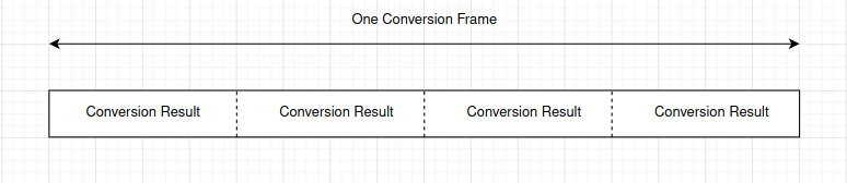
ADC continuous mode conversion is made up with multiple Conversion Frames.
- Conversion Frame: One Conversion Frame contains multiple Conversion Results. Conversion Frame size is configured in adc_continuous_new_handle(), in bytes.
- Conversion Result: One Conversion Result contains multiple bytes (see SOC_ADC_DIGI_RESULT_BYTES). Its structure is adc_digi_output_data_t, including ADC unit, ADC channel and raw data.
Functional Overview
The following sections of this document cover the typical steps to install the ADC continuous mode driver, and read ADC conversion results from group of ADC channels continuously:
Resource Allocation - covers which parameters should be set up to initialize the ADC continuous mode driver and how to deinitialize it.
ADC Configurations - describes how to configure the ADC(s) to make it work under continuous mode.
ADC Control - describes ADC control functions.
Register Event Callbacks - describes how to hook user specific code to an ADC continuous mode event callback function.
Read Conversion Result - covers how to get ADC conversion result.
Hardware Limitations - describes the ADC related hardware limitations.
Power Management - covers power management related.
IRAM Safe - covers the IRAM safe functions.
Thread Safety - lists which APIs are guaranteed to be thread safe by the driver.
Resource Allocation
The ADC continuous mode driver is implemented based on ESP32 SAR ADC module. Different ESP targets might have different number of independent ADCs.
To create an ADC continuous mode driver handle, set up the required configuration structure adc_continuous_handle_cfg_t:
adc_continuous_handle_cfg_t::max_store_buf_sizeset the maximum size (in bytes) of the pool that the driver saves ADC conversion result into. If this pool is full, new conversion results will be lost.adc_continuous_handle_cfg_t::conv_frame_sizeset the size of the ADC conversion frame, in bytes.
After setting up above configurations for the ADC, call adc_continuous_new_handle() with the prepared adc_continuous_handle_cfg_t. This function may fail due to various errors such as invalid argumemts, insufficient memory, etc.
Especially, when this function returns ESP_ERR_NOT_FOUND, this means the I2S0 peripheral is in use. See Hardware Limitations for more information.
If the ADC continuous mode driver is no longer used, you should deinitialize the driver by calling adc_continuous_deinit().
Initialize the ADC Continuous Mode Driver
adc_continuous_handle_cfg_t adc_config = {
    .max_store_buf_size = 1024,
    .conv_frame_size = 100,
};
ESP_ERROR_CHECK(adc_continuous_new_handle(&adc_config));
Recycle the ADC Unit
ESP_ERROR_CHECK(adc_continuous_deinit());
ADC Configurations
After the ADC continuous mode driver is initialized, set up the adc_continuous_config_t to configure ADC IOs to measure analog signal:
adc_continuous_config_t::pattern_num, number of ADC channels that will be used.adc_continuous_config_t::adc_pattern, list of configs for each ADC channel that will be used, see below description.adc_continuous_config_t::sample_freq_hz, expected ADC sampling frequency in Hz.adc_continuous_config_t::conv_mode, continuous conversion mode.adc_continuous_config_t::format, conversion output format.
For adc_digi_pattern_config_t:
adc_digi_pattern_config_t::atten, ADC attenuation. Refer to the On-Chip Sensor chapter in TRM.adc_digi_pattern_config_t::channel, the IO corresponding ADC channel number. See below note.adc_digi_pattern_config_t::unit, the ADC that the IO is subordinate to.adc_digi_pattern_config_t::bit_width, the bitwidth of the raw conversion result.
备注
For the IO corresponding ADC channel number. Check datasheet to acquire the ADC IOs.
On the other hand, adc_continuous_io_to_channel() and adc_continuous_channel_to_io() can be used to acquire the ADC channels and ADC IOs.
To make these settings take effect, call adc_continuous_config() with the configuration structure above.
This API may fail due to reasons like ESP_ERR_INVALID_ARG. When it returns ESP_ERR_INVALID_STATE, this means the ADC continuous mode driver is started, you shouldn’t call this API at this moment.
See ADC continuous mode example peripherals/adc/continuous_read to see configuration codes.
ADC Control
Start and Stop
Calling adc_continuous_start() will make the ADC start to measure analog signals from the configured ADC channels, and generate the conversion results.
On the contrary, calling adc_continuous_stop() will stop the ADC conversion.
ESP_ERROR_CHECK(adc_continuous_stop());
Register Event Callbacks
By calling adc_continuous_register_event_callbacks(), you can hook your own function to the driver ISR. Supported event callbacks are listed in adc_continuous_evt_cbs_t
- adc_continuous_evt_cbs_t::on_conv_done, this is invoked when one conversion frame finishes.
- adc_continuous_evt_cbs_t::on_pool_ovf, this is invoked when internal pool is full. Newer conversion results will be discarded.
As above callbacks are called in an ISR context, you should always ensure the callback function is suitable for an ISR context. Blocking logics should not appear in these callbacks. Callback function prototype is declared in adc_continuous_callback_t.
You can also register your own context when calling adc_continuous_register_event_callbacks(), by the parameter user_data. This user data will be passed to the callback functions directly.
This function may fail due to reasons like ESP_ERR_INVALID_ARG. Specially, when CONFIG_ADC_CONTINUOUS_ISR_IRAM_SAFE is enabled, this error may indicate that the callback functions aren’t in internal RAM. Check error log to know this. Besides, when it fails due to ESP_ERR_INVALID_STATE, this means the ADC continuous mode driver is started, you shouldn’t add callback at this moment.
Conversion Done Event
The driver will fill in the event data of a adc_continuous_evt_cbs_t::on_conv_done event. Event data contains a buffer pointer to a conversion frame buffer, together with the size. Refer to adc_continuous_evt_data_t to know the event data structure.
备注
It is worth noting that, the data buffer adc_continuous_evt_data_t::conv_frame_buffer is maintained by the driver itself. Therefore, never free this piece of memory.
备注
When the Kconfig option CONFIG_ADC_CONTINUOUS_ISR_IRAM_SAFE is enabled, the registered callbacks and the functions called by the callbacks should be placed in IRAM. The involved variables should be placed in internal RAM as well.
Pool Overflow Event
The ADC continuous mode driver has an internal pool to save the conversion results. When the pool is full, a pool overflow event will emerge. Under this condition, the driver won’t fill in the event data. This usually happens the speed to read data from the pool (by calling adc_continuous_read()) is much slower than the ADC conversion speed.
Read Conversion Result
After calling adc_continuous_start(), the ADC continuous conversion starts. Call adc_continuous_read() to get the conversion results of the ADC channels. You need to provide a buffer to get the raw results.
This function will try to read the expected length of conversion results each time.
If the requested length isn’t reached, the function will still move the data from the internal pool to the buffer you prepared. Therefore, check the out_length to know the actual size of conversion results.
If there is no conversion result generated in the internal pool, the function will block for timeout_ms until the conversion results are generated. If there is still no generated results, the function will return
ESP_ERR_TIMEOUT.If the generated results fill up the internal pool, new generated results will be lost. Next time when the
adc_continuous_read()is called, this function will returnESP_ERR_INVALID_STATEindicating this situation.
This API aims to give you a chance to read all the ADC continuous conversion results.
The ADC conversion results read from above function are raw data. To calculate the voltage based on the ADC raw results, this formula can be used:
Vout = Dout * Vmax / Dmax (1)
where:
Vout |
Digital output result, standing for the voltage. |
Dout |
ADC raw digital reading result. |
Vmax |
Maximum measurable input analog voltage, this is related to the ADC attenuation, please refer to the On-Chip Sensor chapter in TRM. |
Dmax |
Maximum of the output ADC raw digital reading result, which is 2^bitwidth, where bitwidth is the :cpp:member::adc_digi_pattern_config_t:bit_width configured before. |
To do further calbration to convert the ADC raw result to voltage in mV, please refer to calibration doc Analog to Digital Converter (ADC) Calibration Driver.
Hardware Limitations
A specific ADC unit can only work under one operating mode at any one time, either Continuous Mode or Oneshot Mode.
adc_continuous_start()has provided the protection.Random Number Generator uses ADC as an input source. When ADC continuous mode driver works, the random number generated from RNG will be less random.
ADC2 is also used by the Wi-Fi.
adc_continuous_start()has provided the protection between Wi-Fi driver and ADC continuous mode driver.
ADC continuous mode driver uses I2S0 peripheral as hardware DMA fifo. Therefore, if I2S0 is in use already, the
adc_continuous_new_handle()will returnESP_ERR_NOT_FOUND.ESP32 DevKitC: GPIO 0 cannot be used due to external auto program circuits.
ESP-WROVER-KIT: GPIO 0, 2, 4 and 15 cannot be used due to external connections for different purposes.
Power Management
When power management is enabled (i.e. CONFIG_PM_ENABLE is on), the APB clock frequency may be adjusted when the system is in an idle state, thus potentially changing the behavior of ADC continuous conversion.
However, the continuous mode driver can prevent this change by acquiring a power management lock of type ESP_PM_APB_FREQ_MAX. The lock is acquired after the continuous conversion is started by adc_continuous_start(). Similarly, the lock will be released after adc_continuous_stop(). Therefore, adc_continuous_start() and adc_continuous_stop() should appear in pairs, otherwise the power management will be out of action.
IRAM Safe
All the ADC continuous mode driver APIs are not IRAM-safe. They are not supposed to be run when the Cache is disabled. By enabling the Kconfig option CONFIG_ADC_CONTINUOUS_ISR_IRAM_SAFE, driver internal ISR handler is IRAM-safe, which means even when the Cache is disabled, the driver will still save the conversion results into its internal pool.
Thread Safety
ADC continuous mode driver APIs are not guaranteed to be thread safe. However, the share hardware mutual exclusion is provided by the driver. See Hardware Limitations for more details.
Application Examples
ADC continuous mode example: peripherals/adc/continuous_read.
API Reference
Header File
Functions
-
esp_err_t adc_continuous_new_handle(const adc_continuous_handle_cfg_t *hdl_config, adc_continuous_handle_t *ret_handle)
Initialize ADC continuous driver and get a handle to it.
- 参数
hdl_config – [in] Pointer to ADC initilization config. Refer to
adc_continuous_handle_cfg_t.ret_handle – [out] ADC continuous mode driver handle
- 返回
ESP_ERR_INVALID_ARG If the combination of arguments is invalid.
ESP_ERR_NOT_FOUND No free interrupt found with the specified flags
ESP_ERR_NO_MEM If out of memory
ESP_OK On success
-
esp_err_t adc_continuous_config(adc_continuous_handle_t handle, const adc_continuous_config_t *config)
Set ADC continuous mode required configurations.
- 参数
handle – [in] ADC continuous mode driver handle
config – [in] Refer to
adc_digi_config_t.
- 返回
ESP_ERR_INVALID_STATE: Driver state is invalid, you shouldn’t call this API at this moment
ESP_ERR_INVALID_ARG: If the combination of arguments is invalid.
ESP_OK: On success
-
esp_err_t adc_continuous_register_event_callbacks(adc_continuous_handle_t handle, const adc_continuous_evt_cbs_t *cbs, void *user_data)
Register callbacks.
备注
User can deregister a previously registered callback by calling this function and setting the to-be-deregistered callback member int the
cbsstructure to NULL.备注
When CONFIG_ADC_CONTINUOUS_ISR_IRAM_SAFE is enabled, the callback itself and functions called by it should be placed in IRAM. Involved variables (including
user_data) should be in internal RAM as well.备注
You should only call this API when the ADC continuous mode driver isn’t started. Check return value to know this.
- 参数
handle – [in] ADC continuous mode driver handle
cbs – [in] Group of callback functions
user_data – [in] User data, which will be delivered to the callback functions directly
- 返回
ESP_OK: On success
ESP_ERR_INVALID_ARG: Invalid arguments
ESP_ERR_INVALID_STATE: Driver state is invalid, you shouldn’t call this API at this moment
-
esp_err_t adc_continuous_start(adc_continuous_handle_t handle)
Start the ADC under continuous mode. After this, the hardware starts working.
- 参数
handle – [in] ADC continuous mode driver handle
- 返回
ESP_ERR_INVALID_STATE Driver state is invalid.
ESP_OK On success
-
esp_err_t adc_continuous_read(adc_continuous_handle_t handle, uint8_t *buf, uint32_t length_max, uint32_t *out_length, uint32_t timeout_ms)
Read bytes from ADC under continuous mode.
- 参数
handle – [in] ADC continuous mode driver handle
buf – [out] Conversion result buffer to read from ADC. Suggest convert to
adc_digi_output_data_tforADC Conversion Results. See@brief Driver Backgroundsto know this concept.length_max – [in] Expected length of the Conversion Results read from the ADC, in bytes.
out_length – [out] Real length of the Conversion Results read from the ADC via this API, in bytes.
timeout_ms – [in] Time to wait for data via this API, in millisecond.
- 返回
ESP_ERR_INVALID_STATE Driver state is invalid. Usually it means the ADC sampling rate is faster than the task processing rate.
ESP_ERR_TIMEOUT Operation timed out
ESP_OK On success
-
esp_err_t adc_continuous_stop(adc_continuous_handle_t handle)
Stop the ADC. After this, the hardware stops working.
- 参数
handle – [in] ADC continuous mode driver handle
- 返回
ESP_ERR_INVALID_STATE Driver state is invalid.
ESP_OK On success
-
esp_err_t adc_continuous_deinit(adc_continuous_handle_t handle)
Deinitialize the ADC continuous driver.
- 参数
handle – [in] ADC continuous mode driver handle
- 返回
ESP_ERR_INVALID_STATE Driver state is invalid.
ESP_OK On success
-
esp_err_t adc_continuous_io_to_channel(int io_num, adc_unit_t *unit_id, adc_channel_t *channel)
Get ADC channel from the given GPIO number.
- 参数
io_num – [in] GPIO number
unit_id – [out] ADC unit
channel – [out] ADC channel
- 返回
ESP_OK: On success
ESP_ERR_INVALID_ARG: Invalid argument
ESP_ERR_NOT_FOUND: The IO is not a valid ADC pad
-
esp_err_t adc_continuous_channel_to_io(adc_unit_t unit_id, adc_channel_t channel, int *io_num)
Get GPIO number from the given ADC channel.
- 参数
unit_id – [in] ADC unit
channel – [in] ADC channel
io_num – [out] GPIO number
- – ESP_OK: On success
ESP_ERR_INVALID_ARG: Invalid argument
Structures
-
struct adc_continuous_handle_cfg_t
ADC continuous mode driver initial configurations.
-
struct adc_continuous_config_t
ADC continuous mode driver configurations.
Public Members
-
uint32_t pattern_num
Number of ADC channels that will be used.
-
adc_digi_pattern_config_t *adc_pattern
List of configs for each ADC channel that will be used.
-
uint32_t sample_freq_hz
The expected ADC sampling frequency in Hz. Please refer to
soc/soc_caps.hto know available sampling frequency range
-
adc_digi_convert_mode_t conv_mode
ADC DMA conversion mode, see
adc_digi_convert_mode_t.
-
adc_digi_output_format_t format
ADC DMA conversion output format, see
adc_digi_output_format_t.
-
uint32_t pattern_num
-
struct adc_continuous_evt_data_t
Event data structure.
备注
The
conv_frame_bufferis maintained by the driver itself, so never free this piece of memory.
-
struct adc_continuous_evt_cbs_t
Group of ADC continuous mode callbacks.
备注
These callbacks are all running in an ISR environment.
备注
When CONFIG_ADC_CONTINUOUS_ISR_IRAM_SAFE is enabled, the callback itself and functions called by it should be placed in IRAM. Involved variables should be in internal RAM as well.
Public Members
-
adc_continuous_callback_t on_conv_done
Event callback, invoked when one conversion frame is done. See
@brief Driver Backgroundsto konwconversion frameconcept.
-
adc_continuous_callback_t on_pool_ovf
Event callback, invoked when the internal pool is full.
-
adc_continuous_callback_t on_conv_done
Macros
-
ADC_MAX_DELAY
Driver Backgrounds.
Type Definitions
-
typedef struct adc_continuous_ctx_t *adc_continuous_handle_t
Type of adc continuous mode driver handle.
-
typedef bool (*adc_continuous_callback_t)(adc_continuous_handle_t handle, const adc_continuous_evt_data_t *edata, void *user_data)
Prototype of ADC continuous mode event callback.
- Param handle
[in] ADC continuous mode driver handle
- Param edata
[in] Pointer to ADC contunuous mode event data
- Param user_data
[in] User registered context, registered when in
adc_continuous_register_event_callbacks()- Return
Whether a high priority task is woken up by this function