I2C 驱动程序
概述
I2C 是一种串行同步半双工通信协议,总线上可以同时挂载多个主机和从机。I2C 总线由串行数据线 (SDA) 和串行时钟线 (SCL) 线构成。这些线都需要上拉电阻。
I2C 具有简单且制造成本低廉等优点,主要用于低速外围设备的短距离通信(一英尺以内)。
ESP32 有2个 I2C 控制器(也称为端口),负责处理在 I2C 总线上的通信。每个控制器都可以设置为主机或从机。
驱动程序的功能
I2C 驱动程序管理在 I2C 总线上设备的通信,该驱动程序具备以下功能:
在主机模式下读写字节
支持从机模式
读取并写入寄存器,然后由主机读取/写入
使用驱动程序
以下部分将指导您完成 I2C 驱动程序配置和工作的基本步骤:
配置驱动程序 - 设置初始化参数(如主机模式或从机模式,SDA 和 SCL 使用的 GPIO 管脚,时钟速度等)
安装驱动程序- 激活一个 I2C 控制器的驱动,该控制器可为主机也可为从机
根据是为主机还是从机配置驱动程序,选择合适的项目
主机模式下通信 - 发起通信(主机模式)
从机模式下通信 - 响应主机消息(从机模式)
中断处理 - 配置 I2C 中断服务
用户自定义配置 - 调整默认的 I2C 通信参数(如时序、位序等)
错误处理 - 如何识别和处理驱动程序配置和通信错误
删除驱动程序- 在通信结束时释放 I2C 驱动程序所使用的资源
配置驱动程序
建立 I2C 通信第一步是配置驱动程序,这需要设置 i2c_config_t 结构中的几个参数:
设置 I2C 工作模式 - 从
i2c_mode_t中选择主机模式或从机模式设置 通信管脚
指定 SDA 和 SCL 信号使用的 GPIO 管脚
是否启用 ESP32 的内部上拉电阻
(仅限主机模式)设置 I2C 时钟速度
(仅限从机模式)设置以下内容:
是否应启用 10 位寻址模式
定义 从机地址
然后,初始化给定 I2C 端口的配置,请使用端口号和 i2c_config_t 作为函数调用参数来调用 i2c_param_config() 函数。
配置示例(主机):
int i2c_master_port = 0;
i2c_config_t conf = {
    .mode = I2C_MODE_MASTER,
    .sda_io_num = I2C_MASTER_SDA_IO,         // select GPIO specific to your project
    .sda_pullup_en = GPIO_PULLUP_ENABLE,
    .scl_io_num = I2C_MASTER_SCL_IO,         // select GPIO specific to your project
    .scl_pullup_en = GPIO_PULLUP_ENABLE,
    .master.clk_speed = I2C_MASTER_FREQ_HZ,  // select frequency specific to your project
    // .clk_flags = 0,          /*!< Optional, you can use I2C_SCLK_SRC_FLAG_* flags to choose i2c source clock here. */
};
配置示例(从机):
int i2c_slave_port = I2C_SLAVE_NUM;
i2c_config_t conf_slave = {
    .sda_io_num = I2C_SLAVE_SDA_IO,          // select GPIO specific to your project
    .sda_pullup_en = GPIO_PULLUP_ENABLE,
    .scl_io_num = I2C_SLAVE_SCL_IO,          // select GPIO specific to your project
    .scl_pullup_en = GPIO_PULLUP_ENABLE,
    .mode = I2C_MODE_SLAVE,
    .slave.addr_10bit_en = 0,
    .slave.slave_addr = ESP_SLAVE_ADDR,      // address of your project
    .clk_flags = 0,
};
在此阶段,i2c_param_config() 还将其他 I2C 配置参数设置为 I2C 总线协议规范中定义的默认值。有关默认值及修改默认值的详细信息,请参考 用户自定义配置。
源时钟配置
增加了 时钟源分配器,用于支持不同的时钟源。时钟分配器将选择一个满足所有频率和能力要求的时钟源(如 i2c_config_t::clk_flags 中的要求)。
当 i2c_config_t::clk_flags 为 0 时,时钟分配器将仅根据所需频率进行选择。如果不需要诸如 APB 之类的特殊功能,则可以将时钟分配器配置为仅根据所需频率选择源时钟。为此,请将 i2c_config_t::clk_flags 设置为 0。有关时钟特性,请参见下表。
备注
如果时钟不满足请求的功能,则该时钟不是有效的选项,即,请求的功能中的任何位(clk_flags)在时钟的功能中均为 0。
时钟名称 |
时钟频率 |
SCL 的最大频率 |
时钟功能 |
|---|---|---|---|
APB 时钟 |
80 MHz |
4 MHz |
/ |
对 i2c_config_t::clk_flags 的解释如下:
I2C_SCLK_SRC_FLAG_AWARE_DFS:当 APB 时钟改变时,时钟的波特率不会改变。I2C_SCLK_SRC_FLAG_LIGHT_SLEEP:支持轻度睡眠模式,APB 时钟则不支持。ESP32 可能不支持某些标志,请在使用前阅读技术参考手册。
备注
在主机模式下,SCL 的时钟频率不应大于上表中提到的 SCL 的最大频率。
备注
SCL 的时钟频率会被上拉电阻和线上电容(或是从机电容)一起影响。因此,用户需要自己选择合适的上拉电阻去保证 SCL 时钟频率是准确的。尽管 I2C 协议推荐上拉电阻值为 1K 欧姆到 10K 欧姆,但是需要根据不同的频率需要选择不同的上拉电阻。
通常来说,所选择的频率越高,需要的上拉电阻越小 (但是不要小于 1K 欧姆)。这是因为高电阻会减小电流,这会延长上升时间从而是频率变慢。通常我们推荐的上拉阻值范围为 2K 欧姆到 5K 欧姆,但是用户可能也需要根据他们的实际情况做出一些调整。
安装驱动程序
配置好 I2C 驱动程序后,使用以下参数调用函数 i2c_driver_install() 安装驱动程序:
端口号,从
i2c_port_t中二选一主机或从机模式,从
i2c_mode_t中选择
(仅限从机模式)分配用于在从机模式下发送和接收数据的缓存区大小。I2C 是一个以主机为中心的总线,数据只能根据主机的请求从从机传输到主机。因此,从机通常有一个发送缓存区,供从应用程序写入数据使用。数据保留在发送缓存区中,由主机自行读取。
用于分配中断的标志(请参考 esp_hw_support/include/esp_intr_alloc.h 中 ESP_INTR_FLAG_* 值)
主机模式下通信
安装 I2C 驱动程序后, ESP32 即可与其他 I2C 设备通信。
ESP32 的 I2C 控制器在主机模式下负责与 I2C 从机设备建立通信,并发送命令让从机响应,如进行测量并将结果发给主机。
为优化通信流程,驱动程序提供一个名为 “命令链接” 的容器,该容器应填充一系列命令,然后传递给 I2C 控制器执行。
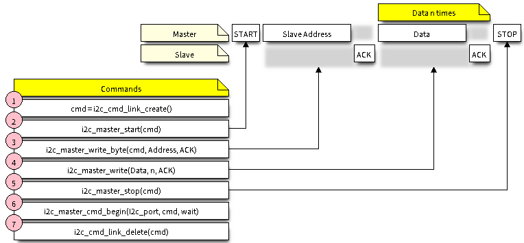
主机写入数据
下面的示例展示如何为 I2C 主机构建命令链接,从而向从机发送 n 个字节。
I2C command link - master write example
下面介绍如何为 “主机写入数据” 设置命令链接及其内部内容:
使用
i2c_cmd_link_create()创建一个命令链接。然后,将一系列待发送给从机的数据填充命令链接:
启动位 -
i2c_master_start()从机地址 -
i2c_master_write_byte()。提供单字节地址作为调用此函数的实参。数据 - 一个或多个字节的数据作为
i2c_master_write()的实参。停止位 -
i2c_master_stop()
函数
i2c_master_write_byte()和i2c_master_write()都有额外的实参,规定主机是否应确认其有无接受到 ACK 位。通过调用
i2c_master_cmd_begin()来触发 I2C 控制器执行命令链接。一旦开始执行,就不能再修改命令链接。命令发送后,通过调用
i2c_cmd_link_delete()释放命令链接使用的资源。
主机读取数据
下面的示例展示如何为 I2C 主机构建命令链接,以便从从机读取 n 个字节。
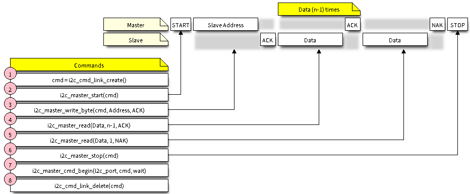
I2C command link - master read example
在读取数据时,在上图的步骤 4 中,不是用 i2c_master_write...,而是用 i2c_master_read_byte() 和/或 i2c_master_read() 填充命令链接。同样,在步骤 5 中配置最后一次的读取,以便主机不提供 ACK 位。
指示写入或读取数据
发送从机地址后(请参考上图中第 3 步),主机可以写入或从从机读取数据。
主机实际执行的操作信息存储在从机地址的最低有效位中。
因此,为了将数据写入从机,主机发送的命令链接应包含地址 (ESP_SLAVE_ADDR << 1) | I2C_MASTER_WRITE,如下所示:
i2c_master_write_byte(cmd, (ESP_SLAVE_ADDR << 1) | I2C_MASTER_WRITE, ACK_EN);
同理,指示从从机读取数据的命令链接如下所示:
i2c_master_write_byte(cmd, (ESP_SLAVE_ADDR << 1) | I2C_MASTER_READ, ACK_EN);
从机模式下通信
安装 I2C 驱动程序后, ESP32 即可与其他 I2C 设备通信。
API 为从机提供以下功能:
-
当主机将数据写入从机时,从机将自动将其存储在接收缓存区中。从机应用程序可自行调用函数
i2c_slave_read_buffer()。如果接收缓存区中没有数据,此函数还具有一个参数用于指定阻塞时间。这将允许从机应用程序在指定的超时设定内等待数据到达缓存区。 -
发送缓存区是用于存储从机要以 FIFO 顺序发送给主机的所有数据。在主机请求接收前,这些数据一直存储在发送缓存区。函数
i2c_slave_write_buffer()有一个参数,用于指定发送缓存区已满时的块时间。这将允许从机应用程序在指定的超时设定内等待发送缓存区中足够的可用空间。
在 peripherals/i2c 中可找到介绍如何使用这些功能的代码示例。
中断处理
安装驱动程序时,默认情况下会安装中断处理程序。
用户自定义配置
如本节末尾所述 配置驱动程序,函数 i2c_param_config() 在初始化 I2C 端口的驱动程序配置时,也会将几个 I2C 通信参数设置为 I2C 总线协议规范规定的默认值。其他一些相关参数已在 I2C 控制器的寄存器中预先配置。
通过调用下表中提供的专用函数,可以将所有这些参数更改为用户自定义值。请注意,时序值是在 APB 时钟周期中定义。APB 的频率在 I2C_APB_CLK_FREQ 中指定。
要更改的参数 |
函数 |
|---|---|
SCL 脉冲周期的高电平和低电平 |
|
在产生 启动 信号期间使用的 SCL 和 SDA 信号时序 |
|
在产生 停止 信号期间使用的 SCL 和 SDA 信号时序 |
|
从机采样以及主机切换时,SCL 和 SDA 信号之间的时序关系 |
|
I2C 超时 |
|
优先发送/接收最高有效位 (LSB) 或最低有效位 (MSB),可在 |
上述每个函数都有一个 _get_ 对应项来检查当前设置的值。例如,调用 i2c_get_timeout() 来检查 I2C 超时值。
要检查在驱动程序配置过程中设置的参数默认值,请参考文件 driver/i2c.c 并查找带有后缀 _DEFAULT 的定义。
通过函数 i2c_set_pin() 可以为 SDA 和 SCL 信号选择不同的管脚并改变上拉配置。如果要修改已经输入的值,请使用函数 i2c_param_config()。
备注
ESP32 的内部上拉电阻范围为几万欧姆,因此在大多数情况下,它们本身不足以用作 I2C 上拉电阻。建议用户使用阻值在 I2C 总线协议规范规定范围内的上拉电阻。计算阻值的具体方法,可参考 TI 应用说明
错误处理
大多数 I2C 驱动程序的函数在成功完成时会返回 ESP_OK ,或在失败时会返回特定的错误代码。实时检查返回的值并进行错误处理是一种好习惯。驱动程序也会打印日志消息,其中包含错误说明,例如检查输入配置的正确性。有关详细信息,请参考文件 driver/i2c.c 并用后缀 _ERR_STR 查找定义。
使用专用中断来捕获通信故障。例如,如果从机将数据发送回主机耗费太长时间,会触发 I2C_TIME_OUT_INT 中断。详细信息请参考 中断处理。
如果出现通信失败,可以分别为发送和接收缓存区调用 i2c_reset_tx_fifo() 和 i2c_reset_rx_fifo() 来重置内部硬件缓存区。
删除驱动程序
当使用 i2c_driver_install() 建立 I2C 通信,一段时间后不再需要 I2C 通信时,可以通过调用 i2c_driver_delete() 来移除驱动程序以释放分配的资源。
由于函数 i2c_driver_delete() 无法保证线程安全性,请在调用该函数移除驱动程序前务必确保所有的线程都已停止使用驱动程序。
应用示例
I2C 主机和从机示例:peripherals/i2c。
API 参考
Header File
Functions
-
esp_err_t i2c_driver_install(i2c_port_t i2c_num, i2c_mode_t mode, size_t slv_rx_buf_len, size_t slv_tx_buf_len, int intr_alloc_flags)
Install an I2C driver.
备注
Not all Espressif chips can support slave mode (e.g. ESP32C2)
备注
In master mode, if the cache is likely to be disabled(such as write flash) and the slave is time-sensitive,
ESP_INTR_FLAG_IRAMis suggested to be used. In this case, please use the memory allocated from internal RAM in i2c read and write function, because we can not access the psram(if psram is enabled) in interrupt handle function when cache is disabled.- 参数
i2c_num – I2C port number
mode – I2C mode (either master or slave).
slv_rx_buf_len – Receiving buffer size. Only slave mode will use this value, it is ignored in master mode.
slv_tx_buf_len – Sending buffer size. Only slave mode will use this value, it is ignored in master mode.
intr_alloc_flags – Flags used to allocate the interrupt. One or multiple (ORred) ESP_INTR_FLAG_* values. See esp_intr_alloc.h for more info.
- 返回
ESP_OK Success
ESP_ERR_INVALID_ARG Parameter error
ESP_FAIL Driver installation error
-
esp_err_t i2c_driver_delete(i2c_port_t i2c_num)
Delete I2C driver.
备注
This function does not guarantee thread safety. Please make sure that no thread will continuously hold semaphores before calling the delete function.
- 参数
i2c_num – I2C port to delete
- 返回
ESP_OK Success
ESP_ERR_INVALID_ARG Parameter error
-
esp_err_t i2c_param_config(i2c_port_t i2c_num, const i2c_config_t *i2c_conf)
Configure an I2C bus with the given configuration.
- 参数
i2c_num – I2C port to configure
i2c_conf – Pointer to the I2C configuration
- 返回
ESP_OK Success
ESP_ERR_INVALID_ARG Parameter error
-
esp_err_t i2c_reset_tx_fifo(i2c_port_t i2c_num)
reset I2C tx hardware fifo
- 参数
i2c_num – I2C port number
- 返回
ESP_OK Success
ESP_ERR_INVALID_ARG Parameter error
-
esp_err_t i2c_reset_rx_fifo(i2c_port_t i2c_num)
reset I2C rx fifo
- 参数
i2c_num – I2C port number
- 返回
ESP_OK Success
ESP_ERR_INVALID_ARG Parameter error
-
esp_err_t i2c_set_pin(i2c_port_t i2c_num, int sda_io_num, int scl_io_num, bool sda_pullup_en, bool scl_pullup_en, i2c_mode_t mode)
Configure GPIO pins for I2C SCK and SDA signals.
- 参数
i2c_num – I2C port number
sda_io_num – GPIO number for I2C SDA signal
scl_io_num – GPIO number for I2C SCL signal
sda_pullup_en – Enable the internal pullup for SDA pin
scl_pullup_en – Enable the internal pullup for SCL pin
mode – I2C mode
- 返回
ESP_OK Success
ESP_ERR_INVALID_ARG Parameter error
-
esp_err_t i2c_master_write_to_device(i2c_port_t i2c_num, uint8_t device_address, const uint8_t *write_buffer, size_t write_size, TickType_t ticks_to_wait)
Perform a write to a device connected to a particular I2C port. This function is a wrapper to
i2c_master_start(),i2c_master_write(),i2c_master_read(), etc… It shall only be called in I2C master mode.- 参数
i2c_num – I2C port number to perform the transfer on
device_address – I2C device’s 7-bit address
write_buffer – Bytes to send on the bus
write_size – Size, in bytes, of the write buffer
ticks_to_wait – Maximum ticks to wait before issuing a timeout.
- 返回
ESP_OK Success
ESP_ERR_INVALID_ARG Parameter error
ESP_FAIL Sending command error, slave hasn’t ACK the transfer.
ESP_ERR_INVALID_STATE I2C driver not installed or not in master mode.
ESP_ERR_TIMEOUT Operation timeout because the bus is busy.
-
esp_err_t i2c_master_read_from_device(i2c_port_t i2c_num, uint8_t device_address, uint8_t *read_buffer, size_t read_size, TickType_t ticks_to_wait)
Perform a read to a device connected to a particular I2C port. This function is a wrapper to
i2c_master_start(),i2c_master_write(),i2c_master_read(), etc… It shall only be called in I2C master mode.- 参数
i2c_num – I2C port number to perform the transfer on
device_address – I2C device’s 7-bit address
read_buffer – Buffer to store the bytes received on the bus
read_size – Size, in bytes, of the read buffer
ticks_to_wait – Maximum ticks to wait before issuing a timeout.
- 返回
ESP_OK Success
ESP_ERR_INVALID_ARG Parameter error
ESP_FAIL Sending command error, slave hasn’t ACK the transfer.
ESP_ERR_INVALID_STATE I2C driver not installed or not in master mode.
ESP_ERR_TIMEOUT Operation timeout because the bus is busy.
-
esp_err_t i2c_master_write_read_device(i2c_port_t i2c_num, uint8_t device_address, const uint8_t *write_buffer, size_t write_size, uint8_t *read_buffer, size_t read_size, TickType_t ticks_to_wait)
Perform a write followed by a read to a device on the I2C bus. A repeated start signal is used between the
writeandread, thus, the bus is not released until the two transactions are finished. This function is a wrapper toi2c_master_start(),i2c_master_write(),i2c_master_read(), etc… It shall only be called in I2C master mode.- 参数
i2c_num – I2C port number to perform the transfer on
device_address – I2C device’s 7-bit address
write_buffer – Bytes to send on the bus
write_size – Size, in bytes, of the write buffer
read_buffer – Buffer to store the bytes received on the bus
read_size – Size, in bytes, of the read buffer
ticks_to_wait – Maximum ticks to wait before issuing a timeout.
- 返回
ESP_OK Success
ESP_ERR_INVALID_ARG Parameter error
ESP_FAIL Sending command error, slave hasn’t ACK the transfer.
ESP_ERR_INVALID_STATE I2C driver not installed or not in master mode.
ESP_ERR_TIMEOUT Operation timeout because the bus is busy.
-
i2c_cmd_handle_t i2c_cmd_link_create_static(uint8_t *buffer, uint32_t size)
Create and initialize an I2C commands list with a given buffer. All the allocations for data or signals (START, STOP, ACK, …) will be performed within this buffer. This buffer must be valid during the whole transaction. After finishing the I2C transactions, it is required to call
i2c_cmd_link_delete_static().备注
It is highly advised to not allocate this buffer on the stack. The size of the data used underneath may increase in the future, resulting in a possible stack overflow as the macro
I2C_LINK_RECOMMENDED_SIZEwould also return a bigger value. A better option is to use a buffer allocated statically or dynamically (withmalloc).- 参数
buffer – Buffer to use for commands allocations
size – Size in bytes of the buffer
- 返回
Handle to the I2C command link or NULL if the buffer provided is too small, please use
I2C_LINK_RECOMMENDED_SIZEmacro to get the recommended size for the buffer.
-
i2c_cmd_handle_t i2c_cmd_link_create(void)
Create and initialize an I2C commands list with a given buffer. After finishing the I2C transactions, it is required to call
i2c_cmd_link_delete()to release and return the resources. The required bytes will be dynamically allocated.- 返回
Handle to the I2C command link or NULL in case of insufficient dynamic memory.
-
void i2c_cmd_link_delete_static(i2c_cmd_handle_t cmd_handle)
Free the I2C commands list allocated statically with
i2c_cmd_link_create_static.- 参数
cmd_handle – I2C commands list allocated statically. This handle should be created thanks to
i2c_cmd_link_create_static()function
-
void i2c_cmd_link_delete(i2c_cmd_handle_t cmd_handle)
Free the I2C commands list.
- 参数
cmd_handle – I2C commands list. This handle should be created thanks to
i2c_cmd_link_create()function
-
esp_err_t i2c_master_start(i2c_cmd_handle_t cmd_handle)
Queue a “START signal” to the given commands list. This function shall only be called in I2C master mode. Call
i2c_master_cmd_begin()to send all the queued commands.- 参数
cmd_handle – I2C commands list
- 返回
ESP_OK Success
ESP_ERR_INVALID_ARG Parameter error
ESP_ERR_NO_MEM The static buffer used to create
cmd_handleris too smallESP_FAIL No more memory left on the heap
-
esp_err_t i2c_master_write_byte(i2c_cmd_handle_t cmd_handle, uint8_t data, bool ack_en)
Queue a “write byte” command to the commands list. A single byte will be sent on the I2C port. This function shall only be called in I2C master mode. Call
i2c_master_cmd_begin()to send all queued commands.- 参数
cmd_handle – I2C commands list
data – Byte to send on the port
ack_en – Enable ACK signal
- 返回
ESP_OK Success
ESP_ERR_INVALID_ARG Parameter error
ESP_ERR_NO_MEM The static buffer used to create
cmd_handleris too smallESP_FAIL No more memory left on the heap
-
esp_err_t i2c_master_write(i2c_cmd_handle_t cmd_handle, const uint8_t *data, size_t data_len, bool ack_en)
Queue a “write (multiple) bytes” command to the commands list. This function shall only be called in I2C master mode. Call
i2c_master_cmd_begin()to send all queued commands.- 参数
cmd_handle – I2C commands list
data – Bytes to send. This buffer shall remain valid until the transaction is finished. If the PSRAM is enabled and
intr_flagis set toESP_INTR_FLAG_IRAM,datashould be allocated from internal RAM.data_len – Length, in bytes, of the data buffer
ack_en – Enable ACK signal
- 返回
ESP_OK Success
ESP_ERR_INVALID_ARG Parameter error
ESP_ERR_NO_MEM The static buffer used to create
cmd_handleris too smallESP_FAIL No more memory left on the heap
-
esp_err_t i2c_master_read_byte(i2c_cmd_handle_t cmd_handle, uint8_t *data, i2c_ack_type_t ack)
Queue a “read byte” command to the commands list. A single byte will be read on the I2C bus. This function shall only be called in I2C master mode. Call
i2c_master_cmd_begin()to send all queued commands.- 参数
cmd_handle – I2C commands list
data – Pointer where the received byte will the stored. This buffer shall remain valid until the transaction is finished.
ack – ACK signal
- 返回
ESP_OK Success
ESP_ERR_INVALID_ARG Parameter error
ESP_ERR_NO_MEM The static buffer used to create
cmd_handleris too smallESP_FAIL No more memory left on the heap
-
esp_err_t i2c_master_read(i2c_cmd_handle_t cmd_handle, uint8_t *data, size_t data_len, i2c_ack_type_t ack)
Queue a “read (multiple) bytes” command to the commands list. Multiple bytes will be read on the I2C bus. This function shall only be called in I2C master mode. Call
i2c_master_cmd_begin()to send all queued commands.- 参数
cmd_handle – I2C commands list
data – Pointer where the received bytes will the stored. This buffer shall remain valid until the transaction is finished.
data_len – Size, in bytes, of the
databufferack – ACK signal
- 返回
ESP_OK Success
ESP_ERR_INVALID_ARG Parameter error
ESP_ERR_NO_MEM The static buffer used to create
cmd_handleris too smallESP_FAIL No more memory left on the heap
-
esp_err_t i2c_master_stop(i2c_cmd_handle_t cmd_handle)
Queue a “STOP signal” to the given commands list. This function shall only be called in I2C master mode. Call
i2c_master_cmd_begin()to send all the queued commands.- 参数
cmd_handle – I2C commands list
- 返回
ESP_OK Success
ESP_ERR_INVALID_ARG Parameter error
ESP_ERR_NO_MEM The static buffer used to create
cmd_handleris too smallESP_FAIL No more memory left on the heap
-
esp_err_t i2c_master_cmd_begin(i2c_port_t i2c_num, i2c_cmd_handle_t cmd_handle, TickType_t ticks_to_wait)
Send all the queued commands on the I2C bus, in master mode. The task will be blocked until all the commands have been sent out. The I2C port is protected by mutex, so this function is thread-safe. This function shall only be called in I2C master mode.
- 参数
i2c_num – I2C port number
cmd_handle – I2C commands list
ticks_to_wait – Maximum ticks to wait before issuing a timeout.
- 返回
ESP_OK Success
ESP_ERR_INVALID_ARG Parameter error
ESP_FAIL Sending command error, slave hasn’t ACK the transfer.
ESP_ERR_INVALID_STATE I2C driver not installed or not in master mode.
ESP_ERR_TIMEOUT Operation timeout because the bus is busy.
-
int i2c_slave_write_buffer(i2c_port_t i2c_num, const uint8_t *data, int size, TickType_t ticks_to_wait)
Write bytes to internal ringbuffer of the I2C slave data. When the TX fifo empty, the ISR will fill the hardware FIFO with the internal ringbuffer’s data.
备注
This function shall only be called in I2C slave mode.
- 参数
i2c_num – I2C port number
data – Bytes to write into internal buffer
size – Size, in bytes, of
databufferticks_to_wait – Maximum ticks to wait.
- 返回
ESP_FAIL (-1) Parameter error
Other (>=0) The number of data bytes pushed to the I2C slave buffer.
-
int i2c_slave_read_buffer(i2c_port_t i2c_num, uint8_t *data, size_t max_size, TickType_t ticks_to_wait)
Read bytes from I2C internal buffer. When the I2C bus receives data, the ISR will copy them from the hardware RX FIFO to the internal ringbuffer. Calling this function will then copy bytes from the internal ringbuffer to the
datauser buffer.备注
This function shall only be called in I2C slave mode.
- 参数
i2c_num – I2C port number
data – Buffer to fill with ringbuffer’s bytes
max_size – Maximum bytes to read
ticks_to_wait – Maximum waiting ticks
- 返回
ESP_FAIL(-1) Parameter error
Others(>=0) The number of data bytes read from I2C slave buffer.
-
esp_err_t i2c_set_period(i2c_port_t i2c_num, int high_period, int low_period)
Set I2C master clock period.
- 参数
i2c_num – I2C port number
high_period – Clock cycle number during SCL is high level, high_period is a 14 bit value
low_period – Clock cycle number during SCL is low level, low_period is a 14 bit value
- 返回
ESP_OK Success
ESP_ERR_INVALID_ARG Parameter error
-
esp_err_t i2c_get_period(i2c_port_t i2c_num, int *high_period, int *low_period)
Get I2C master clock period.
- 参数
i2c_num – I2C port number
high_period – pointer to get clock cycle number during SCL is high level, will get a 14 bit value
low_period – pointer to get clock cycle number during SCL is low level, will get a 14 bit value
- 返回
ESP_OK Success
ESP_ERR_INVALID_ARG Parameter error
-
esp_err_t i2c_filter_enable(i2c_port_t i2c_num, uint8_t cyc_num)
Enable hardware filter on I2C bus Sometimes the I2C bus is disturbed by high frequency noise(about 20ns), or the rising edge of the SCL clock is very slow, these may cause the master state machine to break. Enable hardware filter can filter out high frequency interference and make the master more stable.
备注
Enable filter will slow down the SCL clock.
- 参数
i2c_num – I2C port number to filter
cyc_num – the APB cycles need to be filtered (0<= cyc_num <=7). When the period of a pulse is less than cyc_num * APB_cycle, the I2C controller will ignore this pulse.
- 返回
ESP_OK Success
ESP_ERR_INVALID_ARG Parameter error
-
esp_err_t i2c_filter_disable(i2c_port_t i2c_num)
Disable filter on I2C bus.
- 参数
i2c_num – I2C port number
- 返回
ESP_OK Success
ESP_ERR_INVALID_ARG Parameter error
-
esp_err_t i2c_set_start_timing(i2c_port_t i2c_num, int setup_time, int hold_time)
set I2C master start signal timing
- 参数
i2c_num – I2C port number
setup_time – clock number between the falling-edge of SDA and rising-edge of SCL for start mark, it’s a 10-bit value.
hold_time – clock num between the falling-edge of SDA and falling-edge of SCL for start mark, it’s a 10-bit value.
- 返回
ESP_OK Success
ESP_ERR_INVALID_ARG Parameter error
-
esp_err_t i2c_get_start_timing(i2c_port_t i2c_num, int *setup_time, int *hold_time)
get I2C master start signal timing
- 参数
i2c_num – I2C port number
setup_time – pointer to get setup time
hold_time – pointer to get hold time
- 返回
ESP_OK Success
ESP_ERR_INVALID_ARG Parameter error
-
esp_err_t i2c_set_stop_timing(i2c_port_t i2c_num, int setup_time, int hold_time)
set I2C master stop signal timing
- 参数
i2c_num – I2C port number
setup_time – clock num between the rising-edge of SCL and the rising-edge of SDA, it’s a 10-bit value.
hold_time – clock number after the STOP bit’s rising-edge, it’s a 14-bit value.
- 返回
ESP_OK Success
ESP_ERR_INVALID_ARG Parameter error
-
esp_err_t i2c_get_stop_timing(i2c_port_t i2c_num, int *setup_time, int *hold_time)
get I2C master stop signal timing
- 参数
i2c_num – I2C port number
setup_time – pointer to get setup time.
hold_time – pointer to get hold time.
- 返回
ESP_OK Success
ESP_ERR_INVALID_ARG Parameter error
-
esp_err_t i2c_set_data_timing(i2c_port_t i2c_num, int sample_time, int hold_time)
set I2C data signal timing
- 参数
i2c_num – I2C port number
sample_time – clock number I2C used to sample data on SDA after the rising-edge of SCL, it’s a 10-bit value
hold_time – clock number I2C used to hold the data after the falling-edge of SCL, it’s a 10-bit value
- 返回
ESP_OK Success
ESP_ERR_INVALID_ARG Parameter error
-
esp_err_t i2c_get_data_timing(i2c_port_t i2c_num, int *sample_time, int *hold_time)
get I2C data signal timing
- 参数
i2c_num – I2C port number
sample_time – pointer to get sample time
hold_time – pointer to get hold time
- 返回
ESP_OK Success
ESP_ERR_INVALID_ARG Parameter error
-
esp_err_t i2c_set_timeout(i2c_port_t i2c_num, int timeout)
set I2C timeout value
- 参数
i2c_num – I2C port number
timeout – timeout value for I2C bus (unit: APB 80Mhz clock cycle)
- 返回
ESP_OK Success
ESP_ERR_INVALID_ARG Parameter error
-
esp_err_t i2c_get_timeout(i2c_port_t i2c_num, int *timeout)
get I2C timeout value
- 参数
i2c_num – I2C port number
timeout – pointer to get timeout value
- 返回
ESP_OK Success
ESP_ERR_INVALID_ARG Parameter error
-
esp_err_t i2c_set_data_mode(i2c_port_t i2c_num, i2c_trans_mode_t tx_trans_mode, i2c_trans_mode_t rx_trans_mode)
set I2C data transfer mode
- 参数
i2c_num – I2C port number
tx_trans_mode – I2C sending data mode
rx_trans_mode – I2C receving data mode
- 返回
ESP_OK Success
ESP_ERR_INVALID_ARG Parameter error
-
esp_err_t i2c_get_data_mode(i2c_port_t i2c_num, i2c_trans_mode_t *tx_trans_mode, i2c_trans_mode_t *rx_trans_mode)
get I2C data transfer mode
- 参数
i2c_num – I2C port number
tx_trans_mode – pointer to get I2C sending data mode
rx_trans_mode – pointer to get I2C receiving data mode
- 返回
ESP_OK Success
ESP_ERR_INVALID_ARG Parameter error
Structures
-
struct i2c_config_t
I2C initialization parameters.
Public Members
-
i2c_mode_t mode
I2C mode
-
int sda_io_num
GPIO number for I2C sda signal
-
int scl_io_num
GPIO number for I2C scl signal
-
bool sda_pullup_en
Internal GPIO pull mode for I2C sda signal
-
bool scl_pullup_en
Internal GPIO pull mode for I2C scl signal
-
uint32_t clk_speed
I2C clock frequency for master mode, (no higher than 1MHz for now)
-
struct i2c_config_t::[anonymous]::[anonymous] master
I2C master config
-
uint8_t addr_10bit_en
I2C 10bit address mode enable for slave mode
-
uint16_t slave_addr
I2C address for slave mode
-
uint32_t maximum_speed
I2C expected clock speed from SCL.
-
struct i2c_config_t::[anonymous]::[anonymous] slave
I2C slave config
-
uint32_t clk_flags
Bitwise of
I2C_SCLK_SRC_FLAG_**FOR_DFS**for clk source choice
-
i2c_mode_t mode
Macros
-
I2C_APB_CLK_FREQ
I2C source clock is APB clock, 80MHz
-
I2C_NUM_MAX
I2C port max
-
I2C_NUM_0
I2C port 0
-
I2C_NUM_1
I2C port 1
-
I2C_SCLK_SRC_FLAG_FOR_NOMAL
Any one clock source that is available for the specified frequency may be choosen
-
I2C_SCLK_SRC_FLAG_AWARE_DFS
For REF tick clock, it won’t change with APB.
-
I2C_SCLK_SRC_FLAG_LIGHT_SLEEP
For light sleep mode.
-
I2C_INTERNAL_STRUCT_SIZE
Minimum size, in bytes, of the internal private structure used to describe I2C commands link.
-
I2C_LINK_RECOMMENDED_SIZE(TRANSACTIONS)
The following macro is used to determine the recommended size of the buffer to pass to
i2c_cmd_link_create_static()function. It requires one parameter,TRANSACTIONS, describing the number of transactions intended to be performed on the I2C port. For example, if one wants to perform a read on an I2C device register,TRANSACTIONSmust be at least 2, because the commands required are the following:write device register
read register content
Signals such as “(repeated) start”, “stop”, “nack”, “ack” shall not be counted.
Type Definitions
-
typedef void *i2c_cmd_handle_t
I2C command handle
Header File
Type Definitions
-
typedef int i2c_port_t
I2C port number, can be I2C_NUM_0 ~ (I2C_NUM_MAX-1).
-
typedef soc_periph_i2c_clk_src_t i2c_clock_source_t
I2C group clock source.
Enumerations
-
enum i2c_mode_t
Values:
-
enumerator I2C_MODE_SLAVE
I2C slave mode
-
enumerator I2C_MODE_MASTER
I2C master mode
-
enumerator I2C_MODE_MAX
-
enumerator I2C_MODE_SLAVE
-
enum i2c_rw_t
Values:
-
enumerator I2C_MASTER_WRITE
I2C write data
-
enumerator I2C_MASTER_READ
I2C read data
-
enumerator I2C_MASTER_WRITE
-
enum i2c_trans_mode_t
Values:
-
enumerator I2C_DATA_MODE_MSB_FIRST
I2C data msb first
-
enumerator I2C_DATA_MODE_LSB_FIRST
I2C data lsb first
-
enumerator I2C_DATA_MODE_MAX
-
enumerator I2C_DATA_MODE_MSB_FIRST