Inter-IC Sound (I2S)
Introduction
I2S (Inter-IC Sound) is a serial, synchronous communication protocol that is usually used for transmitting audio data between two digital audio devices.
ESP32-S2 contains one I2S peripheral(s). These peripherals can be configured to input and output sample data via the I2S driver.
An I2S bus that communicate in Standard or TDM mode consists of the following lines:
MCLK: Master clock line. It’s an optional signal depends on slave side, mainly used for offering a reference clock to the I2S slave device.
BCLK: Bit clock line. The bit clock for data line.
WS: Word(Slot) select line. It is usually used to identify the vocal tract except PDM mode.
DIN/DOUT: Serial data input/output line. (Data will loopback internally if din and dout are set to a same GPIO)
Each I2S controller has the following features that can be configured by the I2S driver:
Operation as system master or slave
Capable of acting as transmitter or receiver
DMA controller that allows for streaming sample data without requiring the CPU to copy each data sample
Each controller can operate in simplex communication mode. Thus, the two controllers can be combined to establish full-duplex communication.
I2S File Structure
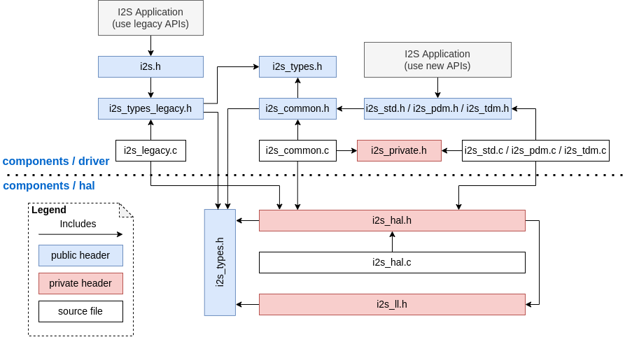
Public headers that need to be included in the I2S application
i2s.h: The header file of legacy I2S APIs (for apps using legacy driver).i2s_std.h: The header file that provides standard communication mode specific APIs (for apps using new driver with standard mode).i2s_pdm.h: The header file that provides PDM communication mode specific APIs (for apps using new driver with PDM mode).i2s_tdm.h: The header file that provides TDM communication mode specific APIs (for apps using new driver with TDM mode).
备注
The legacy driver can’t coexist with the new driver. Including i2s.h to use the legacy driver or the other three headers to use the new driver. The legacy driver might be removed in future.
Public headers that have been included in the headers above
i2s_types_legacy.h: The legacy public types that only used in the legacy driver.i2s_types.h: The header file that provides public types.i2s_common.h: The header file that provides common APIs for all communication modes.
I2S Clock
Clock Source
i2s_clock_src_t::I2S_CLK_SRC_DEFAULT: Default PLL clock.
i2s_clock_src_t::I2S_CLK_SRC_PLL_160M: 160 MHz PLL clock.
i2s_clock_src_t::I2S_CLK_SRC_APLL: Audio PLL clock, more precise thanI2S_CLK_SRC_PLL_160Min high sample rate applications. Its frequency is configurable according to the sample rate, but if APLL has been occupied by emac or other channels already, the APLL frequency is not allowed to change, the driver will try to work under this APLL frequency, if this APLL frequency can’t meet the requirements of I2S, the clock configuration will fail.
Clock Terminology
sample rate: The number of sampled data in one second per slot.
sclk: Source clock frequency. It is the frequency of the clock source.
mclk: Master clock frequency.
bclkis generate from this clock,mclkis mostly needed in the case that requires the MCLK signal as a reference clock to synchronize BCLK and WS between I2S master role and slave role.bclk: Bit clock frequency. Every tick of this clock stands for one data bit on data pin. It means there will be 8/16/24/32
bclkticks in one slot, because the number ofbclkticks in one slot is equal to thei2s_std_slot_config_t::slot_bit_width.lrck / ws: Left/Right clock or word select clock. For non-PDM mode, its frequency is equal to the sample rate.
备注
Normally mclk should be the multiple of sample rate and bclk at the same time. This field i2s_std_clk_config_t::mclk_multiple means the multiple of mclk to the sample rate. If slot_bit_width is set to I2S_SLOT_BIT_WIDTH_24BIT, to keep mclk a multiple to the bclk, i2s_std_clk_config_t::mclk_multiple should be set to I2S_MCLK_MULTIPLE_384, otherwise the ws will be inaccurate. But in the most other cases, I2S_MCLK_MULTIPLE_256 should be enough.
I2S Communication Mode
Overview of All Modes
Target |
Standard |
PDM TX |
PDM RX |
TDM |
ADC/DAC |
LCD/Camera |
|---|---|---|---|---|---|---|
ESP32 |
I2S 0/1 |
I2S 0 |
I2S 0 |
none |
I2S 0 |
I2S 0 |
ESP32S2 |
I2S 0 |
none |
none |
none |
none |
I2S 0 |
ESP32C3 |
I2S 0 |
I2S 0 |
none |
I2S0 |
none |
none |
ESP32S3 |
I2S 0/1 |
I2S 0 |
I2S 0 |
I2S 0/1 |
none |
none |
Standard Mode
Standard mode always has left and right two sound channels which are called ‘slots’. These slots can support 8/16/24/32 bits width sample data. And the communication format for the slots mainly includes these following formats:
Philips Format: Data signal have one bit shift comparing to the WS(word select) signal. And the duty of WS signal is 50%.
MSB Format: Almost same as philips format, but its data have no shift.
PCM Short Format: Data have one bit shift and meanwhile WS signal becomes a pulse lasting one BCLK(Bit Clock) cycle.
Functional Overview
The I2S driver offers following services:
Resources Management
There are three levels’ resources in I2S driver:
platform level: Resources of all I2S controllers in the current target.controller level: Resources in one I2S controller.channel level: Resources of tx or rx channel in one I2S controller.
The public APIs are all channel level APIs, the channel handle i2s_chan_handle_t can help user to manage the resources under a specific channel without considering the other two levels. The other two upper levels’ resources are private and will be managed by the driver automatically. Users can call i2s_new_channel() to allocate a channel handle and call i2s_del_channel() to delete it.
Power Management
When the power management is enabled (i.e. CONFIG_PM_ENABLE is on), the system will adjust or stop the source clock of I2S before going into light sleep, thus potentially changing the I2S signals and leading to transmitting or receiving invalid data.
I2S driver can prevent the system from changing or stopping the source clock by acquiring a power management lock. When the source clock is generated from APB, the lock type will be set to esp_pm_lock_type_t::ESP_PM_APB_FREQ_MAX and when the source clock is APLL (if target support APLL), it will be set to esp_pm_lock_type_t::ESP_PM_NO_LIGHT_SLEEP. Whenever user is reading or writing via I2S (i.e. calling i2s_channel_read() or i2s_channel_write()), the driver will guarantee that the power management lock is acquired. Likewise, the driver releases the lock after reading or writing finished.
Finite-State Machine
There are three states for an I2S channel, they are registered, ready and running. Their relationship is shown in the following diagram:
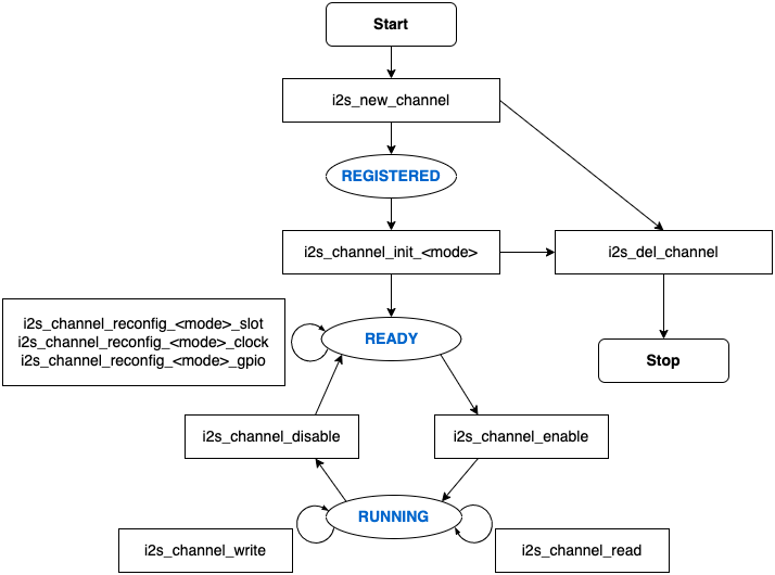
The <mode> in the diagram can be replaced by corresponding I2S communication mode like std for standard two-slot mode, for other information of communication mode, please refer to I2S Communication Mode section.
Data Transport
The data transport of I2S peripheral, including sending and receiving, is realized by DMA. Before transporting data, please call i2s_channel_enable() to enable the specific channel. When the sent or received data reach the size of one DMA buffer, I2S_OUT_EOF or I2S_IN_SUC_EOF interrupt will be triggered. Note that the DMA buffer size is not equal to i2s_chan_config_t::dma_frame_num, one frame here means all the sampled data in one WS circle. Therefore, dma_buffer_size = dma_frame_num * slot_num * slot_bit_width / 8. For the transmit case, users can input the data by calling i2s_channel_write(). This function will help users to copy the data from the source buffer to the DMA tx buffer and wait for the transmition finished. Then it’ll repeat until the sent bytes reach the given size. For the receive case, the function i2s_channel_read() will wait for receiving the message queue which contains the DMA buffer address, it will help users to copy the data from DMA rx buffer to the destination buffer.
Both i2s_channel_write() and i2s_channel_read() are blocking functions, they will keep waiting until the whole source buffer are sent or the whole destination buffer loaded, unless they exceed the max blocking time, then the error code ESP_ERR_TIMEOUT will return in this case. To send or receive data asynchronously, callbacks can be registered by i2s_channel_register_event_callback(), users are able to access the DMA buffer directly in the callback function instead of transmitting or receiving by the two blocking functions. However, please be aware that it is an interrupt callback, don’t do complex logic, floating operation or call non-reentrant functions in the callback.
Configuration Setting
Users can initialize a channel by corresponding function (i.e. i2s_channel_init_std_mode(), i2s_channel_init_pdm_rx_mode(), i2s_channel_init_pdm_tx_mode() or i2s_channel_init_tdm_mode()), the channel will be initialized to the specific mode. If the configurations need to be updated after initialization, i2s_channel_disable() has to be called first to ensure the channel has stopped, and then calling corresponding ‘reconfig’ functions, like i2s_channel_reconfig_std_slot(), i2s_channel_reconfig_std_clock(), i2s_channel_reconfig_std_gpio().
IRAM Safe
By default, the I2S interrupt will be deferred when the Cache is disabled for reasons like writing/erasing Flash. Thus the EOF interrupt will not get executed in time, which is not expected in a real-time application.
There’s a Kconfig option CONFIG_I2S_ISR_IRAM_SAFE that will:
Enable the interrupt being serviced even when cache is disabled
Place driver object into DRAM (in case it’s linked to PSRAM by accident)
This will allow the interrupt to run while the cache is disabled but will come at the cost of increased IRAM consumption.
Thread Safety
All the public I2S APIs are guaranteed to be thread safe by the driver, which means, user can call them from different RTOS tasks without protection by extra locks. Notice that I2S driver uses mutex lock to ensure the thread safety, thus these APIs are not allowed to be used in ISR.
Kconfig Options
CONFIG_I2S_ISR_IRAM_SAFE controls whether the default ISR handler can work when cache is disabled, see IRAM Safe for more information.
CONFIG_I2S_SUPPRESS_DEPRECATE_WARN controls whether to suppress the compiling warning message while using the legacy I2S driver.
CONFIG_I2S_ENABLE_DEBUG_LOG is used to enabled the debug log output. Enable this option will increase the firmware binary size.
Application Example
The examples of the I2S driver can be found in the directory peripherals/i2s. Here are some simple usages of each mode:
Standard TX/RX Usage
Different slot communication formats can be generated by following helper macros for standard mode. As described above, there are three formats in standard mode, their helper macros are:
The clock config helper macro is:
Please refer to Standard Mode for STD API information. And for more details, please refer to driver/include/driver/i2s_std.h.
STD TX Mode
Take 16-bit data width for example, when the data in a uint16_t writting buffer are:
data 0 |
data 1 |
data 2 |
data 3 |
data 4 |
data 5 |
data 6 |
data 7 |
… |
|---|---|---|---|---|---|---|---|---|
0x0001 |
0x0002 |
0x0003 |
0x0004 |
0x0005 |
0x0006 |
0x0007 |
0x0008 |
… |
Here is the table of the real data on the line with different i2s_std_slot_config_t::slot_mode and i2s_std_slot_config_t::slot_mask
data bit width |
slot mode |
slot mask |
ws low |
ws high |
ws low |
ws high |
ws low |
ws high |
ws low |
ws high |
|---|---|---|---|---|---|---|---|---|---|---|
16 bit |
mono |
left |
0x0001 |
0x0000 |
0x0002 |
0x0000 |
0x0003 |
0x0000 |
0x0004 |
0x0000 |
right |
0x0000 |
0x0001 |
0x0000 |
0x0002 |
0x0000 |
0x0003 |
0x0000 |
0x0004 |
||
both |
0x0001 |
0x0001 |
0x0002 |
0x0002 |
0x0003 |
0x0003 |
0x0004 |
0x0004 |
||
stereo |
left |
0x0001 |
0x0001 |
0x0003 |
0x0003 |
0x0005 |
0x0005 |
0x0007 |
0x0007 |
|
right |
0x0002 |
0x0002 |
0x0004 |
0x0004 |
0x0006 |
0x0006 |
0x0008 |
0x0008 |
||
both |
0x0001 |
0x0002 |
0x0003 |
0x0004 |
0x0005 |
0x0006 |
0x0007 |
0x0008 |
备注
Similar for 8-bit and 32-bit data width, the type of the buffer is better to be uint8_t and uint32_t type. But specially, when the data width is 24-bit, the data buffer should aligned with 3-byte(i.e. every 3 bytes stands for a 24-bit data in one slot), additionally, i2s_chan_config_t::dma_frame_num, i2s_std_clk_config_t::mclk_multiple and the writting buffer size should be the multiple of 3, otherwise the data on the line or the sample rate will be incorrect.
#include "driver/i2s_std.h"
#include "driver/gpio.h"

i2s_chan_handle_t tx_handle;
/* Get the default channel configuration by helper macro.
 * This helper macro is defined in 'i2s_common.h' and shared by all the i2s communication mode.
 * It can help to specify the I2S role, and port id */
i2s_chan_config_t chan_cfg = I2S_CHANNEL_DEFAULT_CONFIG(I2S_NUM_AUTO, I2S_ROLE_MASTER);
/* Allocate a new tx channel and get the handle of this channel */
i2s_new_channel(&chan_cfg, &tx_handle, NULL);

/* Setting the configurations, the slot configuration and clock configuration can be generated by the macros
 * These two helper macros is defined in 'i2s_std.h' which can only be used in STD mode.
 * They can help to specify the slot and clock configurations for initialization or updating */
i2s_std_config_t std_cfg = {
    .clk_cfg = I2S_STD_CLK_DEFAULT_CONFIG(48000),
    .slot_cfg = I2S_STD_MSB_SLOT_DEFAULT_CONFIG(I2S_DATA_BIT_WIDTH_32BIT, I2S_SLOT_MODE_STEREO),
    .gpio_cfg = {
        .mclk = I2S_GPIO_UNUSED,
        .bclk = GPIO_NUM_4,
        .ws = GPIO_NUM_5,
        .dout = GPIO_NUM_18,
        .din = I2S_GPIO_UNUSED,
        .invert_flags = {
            .mclk_inv = false,
            .bclk_inv = false,
            .ws_inv = false,
        },
    },
};
/* Initialize the channel */
i2s_channel_init_std_mode(tx_handle, &std_cfg);

/* Before write data, start the tx channel first */
i2s_channel_enable(tx_handle);
i2s_channel_write(tx_handle, src_buf, bytes_to_write, bytes_written, ticks_to_wait);

/* If the configurations of slot or clock need to be updated,
 * stop the channel first and then update it */
// i2s_channel_disable(tx_handle);
// std_cfg.slot_cfg.slot_mode = I2S_SLOT_MODE_MONO; // Default is stereo
// i2s_channel_reconfig_std_slot(tx_handle, &std_cfg.slot_cfg);
// std_cfg.clk_cfg.sample_rate_hz = 96000;
// i2s_channel_reconfig_std_clock(tx_handle, &std_cfg.clk_cfg);

/* Have to stop the channel before deleting it */
i2s_channel_disable(tx_handle);
/* If the handle is not needed any more, delete it to release the channel resources */
i2s_del_channel(tx_handle);
STD RX Mode
Take 16-bit data width for example, when the data on the line are:
ws low |
ws high |
ws low |
ws high |
ws low |
ws high |
ws low |
ws high |
… |
|---|---|---|---|---|---|---|---|---|
0x0001 |
0x0002 |
0x0003 |
0x0004 |
0x0005 |
0x0006 |
0x0007 |
0x0008 |
… |
Here is the table of the data that received in the buffer with different i2s_std_slot_config_t::slot_mode and i2s_std_slot_config_t::slot_mask
data bit width |
slot mode |
slot mask |
data 0 |
data 1 |
data 2 |
data 3 |
data 4 |
data 5 |
data 6 |
data 7 |
|---|---|---|---|---|---|---|---|---|---|---|
16 bit |
mono |
left |
0x0001 |
0x0003 |
0x0005 |
0x0007 |
0x0009 |
0x000b |
0x000d |
0x000f |
right |
0x0002 |
0x0004 |
0x0006 |
0x0008 |
0x000a |
0x000c |
0x000e |
0x0010 |
||
stereo |
any |
0x0001 |
0x0002 |
0x0003 |
0x0004 |
0x0005 |
0x0006 |
0x0007 |
0x0008 |
备注
8-bit, 24-bit and 32-bit are similar as 16-bit, the data bit-width in the receiving buffer are equal to the data bit-width on the line. Additionally, when using 24-bit data width, i2s_chan_config_t::dma_frame_num, i2s_std_clk_config_t::mclk_multiple and the receiving buffer size should be the multiple of 3, otherwise the data on the line or the sample rate will be incorrect.
#include "driver/i2s_std.h"
#include "driver/gpio.h"

i2s_chan_handle_t rx_handle;
/* Get the default channel configuration by helper macro.
 * This helper macro is defined in 'i2s_common.h' and shared by all the i2s communication mode.
 * It can help to specify the I2S role, and port id */
i2s_chan_config_t chan_cfg = I2S_CHANNEL_DEFAULT_CONFIG(I2S_NUM_AUTO, I2S_ROLE_MASTER);
/* Allocate a new rx channel and get the handle of this channel */
i2s_new_channel(&chan_cfg, NULL, &rx_handle);

/* Setting the configurations, the slot configuration and clock configuration can be generated by the macros
 * These two helper macros is defined in 'i2s_std.h' which can only be used in STD mode.
 * They can help to specify the slot and clock configurations for initialization or updating */
i2s_std_config_t std_cfg = {
    .clk_cfg = I2S_STD_CLK_DEFAULT_CONFIG(48000),
    .slot_cfg = I2S_STD_MSB_SLOT_DEFAULT_CONFIG(I2S_DATA_BIT_WIDTH_32BIT, I2S_SLOT_MODE_STEREO),
    .gpio_cfg = {
        .mclk = I2S_GPIO_UNUSED,
        .bclk = GPIO_NUM_4,
        .ws = GPIO_NUM_5,
        .dout = I2S_GPIO_UNUSED,
        .din = GPIO_NUM_19,
        .invert_flags = {
            .mclk_inv = false,
            .bclk_inv = false,
            .ws_inv = false,
        },
    },
};
/* Initialize the channel */
i2s_channel_init_std_mode(rx_handle, &std_cfg);

/* Before read data, start the rx channel first */
i2s_channel_enable(rx_handle);
i2s_channel_read(rx_handle, desc_buf, bytes_to_read, bytes_read, ticks_to_wait);

/* Have to stop the channel before deleting it */
i2s_channel_disable(rx_handle);
/* If the handle is not needed any more, delete it to release the channel resources */
i2s_del_channel(rx_handle);
Full-duplex
Full-duplex mode will register tx and rx channel in an I2S port at the same time, and they will share the BCLK and WS signal. Currently STD and TDM communication mode are able to adopt full-duplex mode in following way, but PDM full-duplex is not supported because PDM TX and RX clock are not same.
Note that one handle can only stand for one channel, the slot and clock configurations for both tx and rx channel should be set one by one.
Here is an example of how to allocate a pair of full-duplex channels:
#include "driver/i2s_std.h"
#include "driver/gpio.h"

i2s_chan_handle_t tx_handle;
i2s_chan_handle_t rx_handle;

/* Allocate a pair of I2S channel */
i2s_chan_config_t chan_cfg = I2S_CHANNEL_DEFAULT_CONFIG(I2S_NUM_AUTO, I2S_ROLE_MASTER);
/* Allocate for tx and rx channel at the same time, then they will work in full-duplex mode */
i2s_new_channel(&chan_cfg, &tx_handle, &rx_handle);

/* Set the configurations for BOTH TWO channels, since tx and rx channel have to be same in full-duplex mode */
i2s_std_config_t std_cfg = {
    .clk_cfg = I2S_STD_CLK_DEFAULT_CONFIG(32000),
    .slot_cfg = I2S_STD_PHILIPS_SLOT_DEFAULT_CONFIG(I2S_DATA_BIT_WIDTH_16BIT, I2S_SLOT_MODE_STEREO),
    .gpio_cfg = {
        .mclk = I2S_GPIO_UNUSED,
        .bclk = GPIO_NUM_4,
        .ws = GPIO_NUM_5,
        .dout = GPIO_NUM_18,
        .din = GPIO_NUM_19,
        .invert_flags = {
            .mclk_inv = false,
            .bclk_inv = false,
            .ws_inv = false,
        },
    },
};
i2s_init_channle(tx_handle, &std_cfg);
i2s_init_channle(rx_handle, &std_cfg);

i2s_channel_enable(tx_handle);
i2s_channel_enable(rx_handle);

...
Simplex Mode
To allocate a channel handle in simplex mode, i2s_new_channel() should be called for each channel. The clock and gpio pins of TX/RX channel on ESP32-S2 are not separate, therefore TX and RX channel can’t coexist on a same I2S port in simplex mode.
#include "driver/i2s_std.h"
#include "driver/gpio.h"

i2s_chan_handle_t tx_handle;
i2s_chan_handle_t rx_handle;

i2s_chan_config_t chan_cfg = I2S_CHANNEL_DEFAULT_CONFIG(I2S_NUM_AUTO, I2S_ROLE_MASTER);
i2s_new_channel(&chan_cfg, &tx_handle, NULL);
i2s_std_config_t std_tx_cfg = {
    .clk_cfg = I2S_STD_CLK_DEFAULT_CONFIG(48000),
    .slot_cfg = I2S_STD_PHILIPS_SLOT_DEFAULT_CONFIG(I2S_DATA_BIT_WIDTH_16BIT, I2S_SLOT_MODE_STEREO),
    .gpio_cfg = {
        .mclk = GPIO_NUM_0,
        .bclk = GPIO_NUM_4,
        .ws = GPIO_NUM_5,
        .dout = GPIO_NUM_18,
        .din = I2S_GPIO_UNUSED,
        .invert_flags = {
            .mclk_inv = false,
            .bclk_inv = false,
            .ws_inv = false,
        },
    },
};
/* Initialize the channel */
i2s_channel_init_std_mode(tx_handle, &std_tx_cfg);
i2s_channel_enable(tx_handle);

/* rx channel will be registered on another I2S, if no other available I2S unit found
 * it will return ESP_ERR_NOT_FOUND */
i2s_new_channel(&chan_cfg, NULL, &rx_handle);
i2s_std_config_t std_rx_cfg = {
    .clk_cfg = I2S_STD_CLK_DEFAULT_CONFIG(16000),
    .slot_cfg = I2S_STD_MSB_SLOT_DEFAULT_CONFIG(I2S_DATA_BIT_WIDTH_32BIT, I2S_SLOT_MODE_STEREO),
    .gpio_cfg = {
        .mclk = I2S_GPIO_UNUSED,
        .bclk = GPIO_NUM_6,
        .ws = GPIO_NUM_7,
        .dout = I2S_GPIO_UNUSED,
        .din = GPIO_NUM_19,
        .invert_flags = {
            .mclk_inv = false,
            .bclk_inv = false,
            .ws_inv = false,
        },
    },
};
i2s_channel_init_std_mode(rx_handle, &std_rx_cfg);
i2s_channel_enable(rx_handle);
Application Notes
How to Prevent Data Lost
For the applications that need a high frequency sample rate, sometimes the massive throughput of receiving data may cause data lost. Users can receive data lost event by registering isr callback function to receive event queue:
static IRAM_ATTR bool i2s_rx_queue_overflow_callback(i2s_chan_handle_t handle, i2s_event_data_t *event, void *user_ctx)
{
    // handle rx queue overflow event ...
    return false;
}

i2s_event_callbacks_t cbs = {
    .on_recv = NULL,
    .on_recv_q_ovf = i2s_rx_queue_overflow_callback,
    .on_sent = NULL,
    .on_send_q_ovf = NULL,
};
TEST_ESP_OK(i2s_channel_register_event_callback(rx_handle, &cbs, NULL));
Please follow these steps to prevent data lost:
Determine the interrupt interval. Generally, when data lost happened, the interval should be the bigger the better, it can help to reduce the interrupt times, i.e.,
dma_frame_numshould be as big as possible while the DMA buffer size won’t exceed its maximum value 4092. The relationships are:interrupt_interval(unit: sec) = dma_frame_num / sample_rate dma_buffer_size = dma_frame_num * slot_num * data_bit_width / 8 <= 4092
Determine the
dma_desc_num. Thedma_desc_numis decided by the max time ofi2s_channel_readpolling cycle, all the received data are supposed to be stored between twoi2s_channel_read. This cycle can be measured by a timer or an outputting gpio signal. The relationship is:dma_desc_num > polling_cycle / interrupt_interval
Determine the receiving buffer size. The receiving buffer that offered by user in
i2s_channel_readshould be able to take all the data in all dma buffers, that means it should be bigger than the total size of all the dma buffers:recv_buffer_size > dma_desc_num * dma_buffer_size
For example, if there is an I2S application, and the known values are:
sample_rate = 144000 Hz
data_bit_width = 32 bits
slot_num = 2
polling_cycle = 10ms
Then the parameters dma_frame_num, dma_desc_num and recv_buf_size can be calculated according to the given known values:
dma_frame_num * slot_num * data_bit_width / 8 = dma_buffer_size <= 4092
dma_frame_num <= 511
interrupt_interval = dma_frame_num / sample_rate = 511 / 144000 = 0.003549 s = 3.549 ms
dma_desc_num > polling_cycle / interrupt_interval = cell(10 / 3.549) = cell(2.818) = 3
recv_buffer_size > dma_desc_num * dma_buffer_size = 3 * 4092 = 12276 bytes
API Reference
Standard Mode
Header File
Functions
-
esp_err_t i2s_channel_init_std_mode(i2s_chan_handle_t handle, const i2s_std_config_t *std_cfg)
Initialize i2s channel to standard mode.
备注
Only allowed to be called when the channel state is REGISTERED, (i.e., channel has been allocated, but not initialized) and the state will be updated to READY if initialization success, otherwise the state will return to REGISTERED.
- 参数
handle – [in] I2S channel handler
std_cfg – [in] Configurations for standard mode, including clock, slot and gpio The clock configuration can be generated by the helper macro
I2S_STD_CLK_DEFAULT_CONFIGThe slot configuration can be generated by the helper macroI2S_STD_PHILIPS_SLOT_DEFAULT_CONFIG,I2S_STD_PCM_SLOT_DEFAULT_CONFIGorI2S_STD_MSB_SLOT_DEFAULT_CONFIG
- 返回
ESP_OK Initialize successfully
ESP_ERR_NO_MEM No memory for storing the channel information
ESP_ERR_INVALID_ARG NULL pointer or invalid configuration
ESP_ERR_INVALID_STATE This channel is not registered
-
esp_err_t i2s_channel_reconfig_std_clock(i2s_chan_handle_t handle, const i2s_std_clk_config_t *clk_cfg)
Reconfigure the I2S clock for standard mode.
备注
Only allowed to be called when the channel state is READY, i.e., channel has been initialized, but not started this function won’t change the state. ‘i2s_channel_disable’ should be called before calling this function if i2s has started.
备注
The input channel handle has to be initialized to standard mode, i.e., ‘i2s_channel_init_std_mode’ has been called before reconfigring
- 参数
handle – [in] I2S channel handler
clk_cfg – [in] Standard mode clock configuration, can be generated by
I2S_STD_CLK_DEFAULT_CONFIG
- 返回
ESP_OK Set clock successfully
ESP_ERR_INVALID_ARG NULL pointer, invalid configuration or not standard mode
ESP_ERR_INVALID_STATE This channel is not initialized or not stopped
-
esp_err_t i2s_channel_reconfig_std_slot(i2s_chan_handle_t handle, const i2s_std_slot_config_t *slot_cfg)
Reconfigure the I2S slot for standard mode.
备注
Only allowed to be called when the channel state is READY, i.e., channel has been initialized, but not started this function won’t change the state. ‘i2s_channel_disable’ should be called before calling this function if i2s has started.
备注
The input channel handle has to be initialized to standard mode, i.e., ‘i2s_channel_init_std_mode’ has been called before reconfigring
- 参数
handle – [in] I2S channel handler
slot_cfg – [in] Standard mode slot configuration, can be generated by
I2S_STD_PHILIPS_SLOT_DEFAULT_CONFIG,I2S_STD_PCM_SLOT_DEFAULT_CONFIGandI2S_STD_MSB_SLOT_DEFAULT_CONFIG.
- 返回
ESP_OK Set clock successfully
ESP_ERR_NO_MEM No memory for DMA buffer
ESP_ERR_INVALID_ARG NULL pointer, invalid configuration or not standard mode
ESP_ERR_INVALID_STATE This channel is not initialized or not stopped
-
esp_err_t i2s_channel_reconfig_std_gpio(i2s_chan_handle_t handle, const i2s_std_gpio_config_t *gpio_cfg)
Reconfigure the I2S gpio for standard mode.
备注
Only allowed to be called when the channel state is READY, i.e., channel has been initialized, but not started this function won’t change the state. ‘i2s_channel_disable’ should be called before calling this function if i2s has started.
备注
The input channel handle has to be initialized to standard mode, i.e., ‘i2s_channel_init_std_mode’ has been called before reconfigring
- 参数
handle – [in] I2S channel handler
gpio_cfg – [in] Standard mode gpio configuration, specified by user
- 返回
ESP_OK Set clock successfully
ESP_ERR_INVALID_ARG NULL pointer, invalid configuration or not standard mode
ESP_ERR_INVALID_STATE This channel is not initialized or not stopped
Structures
-
struct i2s_std_slot_config_t
I2S slot configuration for standard mode.
Public Members
-
i2s_data_bit_width_t data_bit_width
I2S sample data bit width (valid data bits per sample)
-
i2s_slot_bit_width_t slot_bit_width
I2S slot bit width (total bits per slot)
-
i2s_slot_mode_t slot_mode
Set mono or stereo mode with I2S_SLOT_MODE_MONO or I2S_SLOT_MODE_STEREO In TX direction, mono means the written buffer contains only one slot data and stereo means the written buffer contains both left and right data
-
i2s_std_slot_mask_t slot_mask
Select the left, right or both slot
-
uint32_t ws_width
WS signal width (i.e. the number of bclk ticks that ws signal is high)
-
bool ws_pol
WS signal polarity, set true to enable high lever first
-
bool bit_shift
Set to enable bit shift in Philips mode
-
bool msb_right
Set to place right channel data at the MSB in the FIFO
-
i2s_data_bit_width_t data_bit_width
-
struct i2s_std_clk_config_t
I2S clock configuration for standard mode.
Public Members
-
uint32_t sample_rate_hz
I2S sample rate
-
i2s_clock_src_t clk_src
Choose clock source
-
i2s_mclk_multiple_t mclk_multiple
The multiple of mclk to the sample rate Default is 256 in the helper macro, it can satisfy most of cases, but please set this field a multiple of ‘3’ (like 384) when using 24-bit data width, otherwise the sample rate might be inaccurate
-
uint32_t sample_rate_hz
-
struct i2s_std_gpio_config_t
I2S standard mode GPIO pins configuration.
Public Members
-
gpio_num_t mclk
MCK pin, output
-
gpio_num_t bclk
BCK pin, input in slave role, output in master role
-
gpio_num_t ws
WS pin, input in slave role, output in master role
-
gpio_num_t dout
DATA pin, output
-
gpio_num_t din
DATA pin, input
-
uint32_t mclk_inv
Set 1 to invert the mclk output
-
uint32_t bclk_inv
Set 1 to invert the bclk input/output
-
uint32_t ws_inv
Set 1 to invert the ws input/output
-
struct i2s_std_gpio_config_t::[anonymous] invert_flags
GPIO pin invert flags
-
gpio_num_t mclk
-
struct i2s_std_config_t
I2S standard mode major configuration that including clock/slot/gpio configuration.
Public Members
-
i2s_std_clk_config_t clk_cfg
Standard mode clock configuration, can be generated by macro I2S_STD_CLK_DEFAULT_CONFIG
-
i2s_std_slot_config_t slot_cfg
Standard mode slot configuration, can be generated by macros I2S_STD_[mode]_SLOT_DEFAULT_CONFIG, [mode] can be replaced with PHILIPS/MSB/PCM
-
i2s_std_gpio_config_t gpio_cfg
Standard mode gpio configuration, specified by user
-
i2s_std_clk_config_t clk_cfg
Macros
-
I2S_STD_PHILIPS_SLOT_DEFAULT_CONFIG(bits_per_sample, mono_or_stereo)
Philips format in 2 slots.
This file is specified for I2S standard communication mode Features:
Philips/MSB/PCM are supported in standard mode
Fixed to 2 slots
- 参数
bits_per_sample – i2s data bit width
mono_or_stereo – I2S_SLOT_MODE_MONO or I2S_SLOT_MODE_STEREO
-
I2S_STD_PCM_SLOT_DEFAULT_CONFIG(bits_per_sample, mono_or_stereo)
PCM(short) format in 2 slots.
备注
PCM(long) is same as philips in 2 slots
- 参数
bits_per_sample – i2s data bit width
mono_or_stereo – I2S_SLOT_MODE_MONO or I2S_SLOT_MODE_STEREO
-
I2S_STD_MSB_SLOT_DEFAULT_CONFIG(bits_per_sample, mono_or_stereo)
MSB format in 2 slots.
- 参数
bits_per_sample – i2s data bit width
mono_or_stereo – I2S_SLOT_MODE_MONO or I2S_SLOT_MODE_STEREO
-
I2S_STD_CLK_DEFAULT_CONFIG(rate)
i2s default standard clock configuration
备注
Please set the mclk_multiple to I2S_MCLK_MULTIPLE_384 while using 24 bits data width Otherwise the sample rate might be imprecise since the bclk division is not a integer
- 参数
rate – sample rate
I2S Driver
Header File
Functions
-
esp_err_t i2s_new_channel(const i2s_chan_config_t *chan_cfg, i2s_chan_handle_t *ret_tx_handle, i2s_chan_handle_t *ret_rx_handle)
Allocate new I2S channel(s)
备注
The new created I2S channel handle will be REGISTERED state after it is allocated successfully.
备注
When the port id in channel configuration is I2S_NUM_AUTO, driver will allocate I2S port automatically on one of the i2s controller, otherwise driver will try to allocate the new channel on the selected port.
备注
If both tx_handle and rx_handle are not NULL, it means this I2S controller will work at full-duplex mode, the rx and tx channels will be allocated on a same I2S port in this case. Note that some configurations of tx/rx channel are shared on ESP32 and ESP32S2, so please make sure they are working at same condition and under same status(start/stop). Currently, full-duplex mode can’t guarantee tx/rx channels write/read synchronously, they can only share the clock signals for now.
备注
If tx_handle OR rx_handle is NULL, it means this I2S controller will work at simplex mode. For ESP32 and ESP32S2, the whole I2S controller (i.e. both rx and tx channel) will be occupied, even if only one of rx or tx channel is registered. For the other targets, another channel on this controller will still available.
- 参数
chan_cfg – [in] I2S controller channel configurations
ret_tx_handle – [out] I2S channel handler used for managing the sending channel(optional)
ret_rx_handle – [out] I2S channel handler used for managing the receiving channel(optional)
- 返回
ESP_OK Allocate new channel(s) success
ESP_ERR_NOT_SUPPORTED The communication mode is not supported on the current chip
ESP_ERR_INVALID_ARG NULL pointer or illegal parameter in i2s_chan_config_t
ESP_ERR_NOT_FOUND No available I2S channel found
-
esp_err_t i2s_del_channel(i2s_chan_handle_t handle)
Delete the i2s channel.
备注
Only allowed to be called when the i2s channel is at REGISTERED or READY state (i.e., it should stop before deleting it).
备注
Resource will be free automatically if all channels in one port are deleted
- 参数
handle – [in] I2S channel handler
ESP_OK Delete successfully
ESP_ERR_INVALID_ARG NULL pointer
-
esp_err_t i2s_channel_get_info(i2s_chan_handle_t handle, i2s_chan_info_t *chan_info)
Get I2S channel information.
- 参数
handle – [in] I2S channel handler
chan_info – [out] I2S channel basic information
- 返回
ESP_OK Get i2s channel information success
ESP_ERR_NOT_FOUND The input handle doesn’t match any registered I2S channels, it may not an i2s channel handle or not available any more
ESP_ERR_INVALID_ARG The input handle or chan_info pointer is NULL
-
esp_err_t i2s_channel_enable(i2s_chan_handle_t handle)
Enable the i2s channel.
备注
Only allowed to be called when the channel state is READY, (i.e., channel has been initialized, but not started) the channel will enter RUNNING state once it is enabled successfully.
备注
Enbale the channel can start the I2S communication on hardware. It will start outputting bclk and ws signal. For mclk signal, it will start to output when initialization is finished
- 参数
handle – [in] I2S channel handler
ESP_OK Start successfully
ESP_ERR_INVALID_ARG NULL pointer
ESP_ERR_INVALID_STATE This channel has not initialized or already started
-
esp_err_t i2s_channel_disable(i2s_chan_handle_t handle)
Disable the i2s channel.
备注
Only allowed to be called when the channel state is READY / RUNNING, (i.e., channel has been initialized) the channel will enter READY state once it is disabled successfully.
备注
Disable the channel can stop the I2S communication on hardware. It will stop bclk and ws signal but not mclk signal
- 参数
handle – [in] I2S channel handler
- 返回
ESP_OK Stop successfully
ESP_ERR_INVALID_ARG NULL pointer
ESP_ERR_INVALID_STATE This channel has not stated
-
esp_err_t i2s_channel_write(i2s_chan_handle_t handle, const void *src, size_t size, size_t *bytes_written, uint32_t timeout_ms)
I2S write data.
备注
Only allowed to be called when the channel state is RUNNING, (i.e., tx channel has been started and is not writing now) but the RUNNING only stands for the software state, it doesn’t mean there is no the signal transporting on line.
- 参数
handle – [in] I2S channel handler
src – [in] The pointer of sent data buffer
size – [in] Max data buffer length
bytes_written – [out] Byte number that actually be sent
timeout_ms – [in] Max block time
- 返回
ESP_OK Write successfully
ESP_ERR_INVALID_ARG NULL pointer or this handle is not tx handle
ESP_ERR_TIMEOUT Writing timeout, no writing event received from ISR within ticks_to_wait
ESP_ERR_INVALID_STATE I2S is not ready to write
-
esp_err_t i2s_channel_read(i2s_chan_handle_t handle, void *dest, size_t size, size_t *bytes_read, uint32_t timeout_ms)
I2S read data.
备注
Only allowed to be called when the channel state is RUNNING but the RUNNING only stands for the software state, it doesn’t mean there is no the signal transporting on line.
- 参数
handle – [in] I2S channel handler
dest – [in] The pointer of receiving data buffer
size – [in] Max data buffer length
bytes_read – [out] Byte number that actually be read
timeout_ms – [in] Max block time
- 返回
ESP_OK Read successfully
ESP_ERR_INVALID_ARG NULL pointer or this handle is not rx handle
ESP_ERR_TIMEOUT Reading timeout, no reading event received from ISR within ticks_to_wait
ESP_ERR_INVALID_STATE I2S is not ready to read
-
esp_err_t i2s_channel_register_event_callback(i2s_chan_handle_t handle, const i2s_event_callbacks_t *callbacks, void *user_data)
Set event callbacks for I2S channel.
备注
Only allowed to be called when the channel state is REGISTARED / READY, (i.e., before channel starts)
备注
User can deregister a previously registered callback by calling this function and setting the callback member in the
callbacksstructure to NULL.备注
When CONFIG_I2S_ISR_IRAM_SAFE is enabled, the callback itself and functions called by it should be placed in IRAM. The variables used in the function should be in the SRAM as well. The
user_datashould also reside in SRAM or internal RAM as well.- 参数
handle – [in] I2S channel handler
callbacks – [in] Group of callback functions
user_data – [in] User data, which will be passed to callback functions directly
- 返回
ESP_OK Set event callbacks successfully
ESP_ERR_INVALID_ARG Set event callbacks failed because of invalid argument
ESP_ERR_INVALID_STATE Set event callbacks failed because the current channel state is not REGISTARED or READY
Structures
-
struct i2s_event_callbacks_t
Group of I2S callbacks.
备注
The callbacks are all running under ISR environment
备注
When CONFIG_I2S_ISR_IRAM_SAFE is enabled, the callback itself and functions called by it should be placed in IRAM. The variables used in the function should be in the SRAM as well.
Public Members
-
i2s_isr_callback_t on_recv
Callback of data received event, only for rx channel The event data includes DMA buffer address and size that just finished receiving data
-
i2s_isr_callback_t on_recv_q_ovf
Callback of receiving queue overflowed event, only for rx channel The event data includes buffer size that has been overwritten
-
i2s_isr_callback_t on_sent
Callback of data sent event, only for tx channel The event data includes DMA buffer address and size that just finished sending data
-
i2s_isr_callback_t on_send_q_ovf
Callback of sending queue overflowed evnet, only for tx channel The event data includes buffer size that has been overwritten
-
i2s_isr_callback_t on_recv
-
struct i2s_chan_config_t
I2S controller channel configuration.
Public Members
-
i2s_port_t id
I2S port id
-
i2s_role_t role
I2S role, I2S_ROLE_MASTER or I2S_ROLE_SLAVE
-
uint32_t dma_desc_num
I2S DMA buffer number, it is also the number of DMA descriptor
-
uint32_t dma_frame_num
I2S frame number in one DMA buffer. One frame means one-time sample data in all slots, it should be the multiple of ‘3’ when the data bit width is 24.
-
bool auto_clear
Set to auto clear DMA TX buffer, i2s will always send zero automatically if no data to send
-
i2s_port_t id
-
struct i2s_chan_info_t
I2S channel information.
Public Members
-
i2s_port_t id
I2S port id
-
i2s_role_t role
I2S role, I2S_ROLE_MASTER or I2S_ROLE_SLAVE
-
i2s_comm_mode_t mode
I2S channel communication mode
-
i2s_chan_handle_t pair_chan
I2S pair channel handle in duplex mode, always NULL in simplex mode
-
i2s_port_t id
Macros
-
I2S_CHANNEL_DEFAULT_CONFIG(i2s_num, i2s_role)
get default I2S property
-
I2S_GPIO_UNUSED
Used in i2s_gpio_config_t for signals which are not used
I2S Types
Header File
Structures
-
struct i2s_event_data_t
Event structure used in I2S event queue.
Public Members
-
void *data
The pointer of DMA buffer that just finished sending or receiving for
on_recvandon_sentcallback NULL foron_recv_q_ovfandon_send_q_ovfcallback
-
size_t size
The buffer size of DMA buffer when success to send or receive, also the buffer size that dropped when queue overflow. It is related to the dma_frame_num and data_bit_width, typically it is fixed when data_bit_width is not changed.
-
void *data
Type Definitions
-
typedef struct i2s_channel_obj_t *i2s_chan_handle_t
i2s channel object handle, the control unit of the i2s driver
-
typedef bool (*i2s_isr_callback_t)(i2s_chan_handle_t handle, i2s_event_data_t *event, void *user_ctx)
I2S event callback.
- Param handle
[in] I2S channel handle, created from
i2s_new_channel()- Param event
[in] I2S event data
- Param user_ctx
[in] User registered context, passed from
i2s_channel_register_event_callback()- Return
Whether a high priority task has been waken up by this callback function
Enumerations
-
enum i2s_port_t
I2S controller port number, the max port number is (SOC_I2S_NUM -1).
Values:
-
enumerator I2S_NUM_0
I2S controller port 0
-
enumerator I2S_NUM_AUTO
Select whichever port is available
-
enumerator I2S_NUM_0
-
enum i2s_comm_mode_t
I2S controller communication mode.
Values:
-
enumerator I2S_COMM_MODE_STD
I2S controller using standard communication mode, support philips/MSB/PCM format
-
enumerator I2S_COMM_MODE_NONE
Unspecified I2S controller mode
-
enumerator I2S_COMM_MODE_STD
-
enum i2s_mclk_multiple_t
The multiple of mclk to sample rate.
Values:
-
enumerator I2S_MCLK_MULTIPLE_128
mclk = sample_rate * 128
-
enumerator I2S_MCLK_MULTIPLE_256
mclk = sample_rate * 256
-
enumerator I2S_MCLK_MULTIPLE_384
mclk = sample_rate * 384
-
enumerator I2S_MCLK_MULTIPLE_512
mclk = sample_rate * 512
-
enumerator I2S_MCLK_MULTIPLE_128
Header File
Type Definitions
-
typedef soc_periph_i2s_clk_src_t i2s_clock_src_t
I2S clock source
Enumerations
-
enum i2s_slot_mode_t
I2S channel slot mode.
Values:
-
enumerator I2S_SLOT_MODE_MONO
I2S channel slot format mono, transmit same data in all slots for tx mode, only receive the data in the first slots for rx mode.
-
enumerator I2S_SLOT_MODE_STEREO
I2S channel slot format stereo, transmit different data in different slots for tx mode, receive the data in all slots for rx mode.
-
enumerator I2S_SLOT_MODE_MONO
-
enum i2s_dir_t
I2S channel direction.
Values:
-
enumerator I2S_DIR_RX
I2S channel direction RX
-
enumerator I2S_DIR_TX
I2S channel direction TX
-
enumerator I2S_DIR_RX
-
enum i2s_role_t
I2S controller role.
Values:
-
enumerator I2S_ROLE_MASTER
I2S controller master role, bclk and ws signal will be set to output
-
enumerator I2S_ROLE_SLAVE
I2S controller slave role, bclk and ws signal will be set to input
-
enumerator I2S_ROLE_MASTER
-
enum i2s_data_bit_width_t
Available data bit width in one slot.
Values:
-
enumerator I2S_DATA_BIT_WIDTH_8BIT
I2S channel data bit-width: 8
-
enumerator I2S_DATA_BIT_WIDTH_16BIT
I2S channel data bit-width: 16
-
enumerator I2S_DATA_BIT_WIDTH_24BIT
I2S channel data bit-width: 24
-
enumerator I2S_DATA_BIT_WIDTH_32BIT
I2S channel data bit-width: 32
-
enumerator I2S_DATA_BIT_WIDTH_8BIT
-
enum i2s_slot_bit_width_t
Total slot bit width in one slot.
Values:
-
enumerator I2S_SLOT_BIT_WIDTH_AUTO
I2S channel slot bit-width equals to data bit-width
-
enumerator I2S_SLOT_BIT_WIDTH_8BIT
I2S channel slot bit-width: 8
-
enumerator I2S_SLOT_BIT_WIDTH_16BIT
I2S channel slot bit-width: 16
-
enumerator I2S_SLOT_BIT_WIDTH_24BIT
I2S channel slot bit-width: 24
-
enumerator I2S_SLOT_BIT_WIDTH_32BIT
I2S channel slot bit-width: 32
-
enumerator I2S_SLOT_BIT_WIDTH_AUTO
-
enum i2s_std_slot_mask_t
I2S slot select in standard mode.
备注
It has different meanings in tx/rx/mono/stereo mode, and it may have differen behaviors on different targets For the details, please refer to the I2S API reference
Values:
-
enumerator I2S_STD_SLOT_LEFT
I2S transmits or receives left slot
-
enumerator I2S_STD_SLOT_RIGHT
I2S transmits or receives right slot
-
enumerator I2S_STD_SLOT_BOTH
I2S transmits or receives both left and right slot
-
enumerator I2S_STD_SLOT_LEFT
-
enum i2s_pdm_slot_mask_t
I2S slot select in PDM mode.
Values:
-
enumerator I2S_PDM_SLOT_RIGHT
I2S PDM only transmits or receives the PDM device whose ‘select’ pin is pulled up
-
enumerator I2S_PDM_SLOT_LEFT
I2S PDM only transmits or receives the PDM device whose ‘select’ pin is pulled down
-
enumerator I2S_PDM_SLOT_BOTH
I2S PDM transmits or receives both two slots
-
enumerator I2S_PDM_SLOT_RIGHT