ESP Low Power Parameter Configuration
Note
This document is automatically translated using AI. Please excuse any detailed errors. The official English version is still in progress.
Introduction
In Light Sleep mode, the RF module is turned off, and most modules, except for RTC-related ones, are powered down or undergo dynamic frequency adjustment to achieve power reduction. Some menuconfig can be configured as needed, and this article will introduce these configuration items. The chip’s base current at this time can refer to the power consumption on the datasheet, such as ESP32-C3 is 130 μA, ESP32-S3 is 240 μA, ESP32-C6 is 35 μA (the actual measurement is 45 μA, the subsequent datasheet will correct this item).
1. Common Power Optimization Configuration Options
1.1. Dynamic Frequency Adjustment
The higher the frequency at which the CPU works, the greater the power consumption. Through DFS (dynamic frequency scaling), the system can automatically switch the working frequency to balance power consumption and performance. To enable this feature, you need to enable the two items shown in Figure 2-1, so the system will switch to the maximum frequency when working, and switch to the lowest frequency when the system is idle. The maximum frequency is the default main frequency, such as ESP32-C3 is 160 MHz, and the lowest frequency is the frequency of the external main crystal oscillator, generally 40 MHz. The maximum and minimum frequencies can be set by calling esp_pm_configure.
Note
In the scenario of automatic frequency tuning for Wi-Fi applications, it is necessary to ensure that the minimum frequency is not lower than 40 MHz. When the frequency is below 40 MHz, the processing speed of the CPU will be significantly reduced, and the optimization effect in terms of low power consumption will not be obvious either.
Figure 2-1 Dynamic Frequency Adjustment Configuration Items
Configuration item name:
PM_ENABLEConfiguration item path:
(Top) -> Component config -> Power Management -> Support for power managementConfiguration item name:
PM_DFS_INIT_AUTOConfiguration item path:
(Top) -> Component config -> Power Management -> Support for power management -> Enable dynamic frequency scaling (DFS) at startup
1.2 Automatic light sleep
If you need to further reduce power consumption after enabling dynamic frequency adjustment, as shown in Figure 2-1, you need to enable automatic light sleep. Modem sleep mode plus automatic light sleep is what we often call power save mode.
Figure 2-2 Automatic light sleep configuration items
Configuration item name:
FREERTOS_HZConfiguration item path:
(Top) -> Component config -> FreeRTOS -> Tick rate (Hz)Configuration item name:
FREERTOS_USE_TICKLESS_IDLEConfiguration item path:
(Top) -> Component config -> FreeRTOS -> Tickless idle support
This involves two configuration items, item A is the Tick frequency of freeRTOS, the default is 100, that is, each Tick requires 1000 / 100=10 ms. Item B is the minimum idle Tick number required to automatically enter light sleep, the default is 3, that is, when the system detects that the idle time is more than 3 Ticks, it will automatically enter light sleep. As shown in the figure above, when the idle time is more than 3*10=30 ms, the system will automatically enter light sleep. By increasing item A, the system can more sensitively detect idle time and enter sleep. For example, if the tick rate is configured as 1000, that is, if there is no task working within 3 ms, it will enter sleep, thereby achieving lower power consumption.
Note
Automatic entry into light sleep can only be configured after enabling the configuration items in 2.1.
After enabling automatic frequency adjustment and automatic sleep, the communication of some peripherals will be affected. For specific details, please refer to the programming guide.
The most common question from customers is how to use LEDC and UART while maintaining power consumption. The solutions are: - For customers who want to use UART interrupts during automatic sleep, first ask them if they have any spare GPIO pins, and recommend GPIO wake-up as a priority. - Ask the customer if there is an external 32K crystal oscillator on the hardware. If there is, change the peripheral clock source to the external 32K crystal oscillator. - Use locks, which can disable dynamic frequency adjustment during communication. See attachment 2 for an example.
1.3 Isolate GPIO
During system sleep, GPIO leakage will cause current loss and increase system power consumption. In esp-idf, GPIO leakage is eliminated during light sleep by floating (disabling internal pull-up and pull-down resistors) and isolating (disconnecting pin input and output) GPIO pins. The corresponding menuconfig configuration item is as follows.
Note
This configuration item can only be enabled after enabling automatic sleep in 2.2.
Figure 2-3 Isolate GPIO Configuration Item
Configuration item name:
PM_SLP_DISABLE_GPIOConfiguration item path:
(Top) -> Component config -> Power Management -> Disable all GPIO when chip at sleep
When this option is enabled, all GPIO pins will be disabled during system sleep, eliminating the impact of GPIO leakage on sleep power consumption, but also making it impossible for GPIO to input and output signals during sleep. However, in some applications, the application layer hopes to be able to use GPIO functions (input/output/internal pull-up and pull-down) normally during system sleep. Therefore, IDF provides a set of APIs for managing GPIO status during sleep. For related APIs, refer to Table 2-1.
Table 2-1 Sleep Process GPIO Management API
Set the input and output status of GPIO in sleep state:
esp_err_t gpio_sleep_set_direction(gpio_num_t gpio_num, gpio_mode_t mode);
Set the pull-up and pull-down status of GPIO in sleep state:
esp_err_t gpio_sleep_set_pull_mode(gpio_num_t gpio_num, gpio_pull_mode_t pull);
Enable automatic GPIO status switching:
esp_err_t gpio_sleep_sel_en(gpio_num_t gpio_num);
Disable automatic GPIO status switching:
esp_err_t gpio_sleep_sel_dis(gpio_num_t gpio_num);
If you want to maintain the status of the GPIO pin during sleep, such as controlling light output and controlling switch closure, you can use the gpio_hold_en(gpio_num_t gpio_num) and gpio_hold_dis(gpio_num_t gpio_num) APIs to hold the GPIO that needs to maintain the level before entering sleep, and hold_dis after waking up.
1.4 Flash Power Down
ESP32 expands system storage resources through external flash and PSRAM. Flash has the characteristic of not losing data after power loss, while PSRAM cannot retain data after power loss. When PSRAM is not used in the system, the flash power-down function can be enabled to reduce the sleep current of the chip. The related menuconfig options are as follows:
Figure 2-4 Flash Power Down Configuration Item
Configuration item name:
ESP_SYSTEM_PD_FLASH (release/v4.3)Configuration item name:
ESP_SLEEP_POWER_DOWN_FLASH (4.4 and later)Configuration item path:
(Top) -> Component config -> ESP System Settings -> PD flash at light sleep when there is no SPIRAM (release/v4.3)Configuration path:
(Top) -> Component config -> Hardware Settings -> Sleep Config -> Power down flash in light sleep when there is no SPIRAM (4.4 and later)
Note
In reality, the time required for flash power-off is difficult to predict. Even if the time required for complete flash power-off can be known, it is sometimes impossible to ensure the safety of flash power-off by setting a sufficiently long sleep time (for example, sudden asynchronous wake-up sources can make the actual sleep time uncontrollable). At this time, the hardware behavior of re-powering before the power-off is completed may cause the flash to fail to work normally. Therefore, the following adjustments can be made to the configuration items:
Figure 2-5 Flash Power-off Configuration Optimization
Configuration name:
ESP_SLEEP_FLASH_LEAKAGE_WORKAROUNDConfiguration path:
(Top) -> Component config -> Hardware Settings -> Sleep Config -> Pull-up Flash CS pin in light sleep
This method is better than powering off the flash, and it increases the base current consumption by tens of μA, but it takes into account both safety and power consumption. If a filter capacitor is added to the power supply circuit of the flash, it should be avoided as much as possible to power off the flash.
1.5 CPU Power Down
For applications with higher power consumption requirements in light sleep mode, the CPU power-down function can be enabled during sleep to reduce the sleep current. For ESP32-C3, the sleep current is reduced by about 100 μA, and for ESP32-S3, the sleep current is reduced by about 650 μA. Currently, it is only available on these two chips, and ESP32 and ESP32-S2 cannot use it.
Powering down the CPU during sleep will cause the loss of CPU execution context information (dedicated, general, and status registers, etc.), causing the CPU to execute abnormally after waking up from sleep. Therefore, it is necessary to back up the context information to the retention memory before the CPU is powered down. After the system wakes up, the CPU executes the context information from the retention memory before execution. Backing up the CPU context information requires system memory resources. For ESP32-C3, it will consume 1.6 KB of DRAM space, and for ESP32-S3, it will consume 8.58 KB of DRAM space.
Figure 2-6 CPU Power Down Configuration
Configuration name:
PM_POWER_DOWN_CPU_IN_LIGHT_SLEEPConfiguration path:
(Top) -> Component config -> Power Management -> Power down CPU in light sleep
1.6 Peripheral Power Down (light sleep)
By turning off this item, the base current can be reduced by about 100 μA.
Configuration name:
PM_POWER_DOWN_PERIPHERAL_IN_LIGHT_SLEEPConfiguration path:
(Top) -> Component config -> Power Management -> Power down Digital Peripheral in light sleep (EXPERIMENTAL)
When the peripheral power domain is powered off during sleep, the IO_MUX and GPIO modules are both powered off, which means that the state of the chip pins will not be controlled by these modules. To maintain the state of IO during sleep, you need to call gpio_hold_dis() and gpio_hold_en() before and after configuring the GPIO state. This operation can ensure that the IO configuration is latched, preventing IO from floating during sleep.
2. Wi-Fi/Bluetooth Low Power Optimization Configuration
Espressif chips are wireless MCUs, so most of the time, low power functions need to be used with Wi-Fi/Bluetooth functions. Here, some low power configurations and parameters related to Wi-Fi/Bluetooth are explained.
2.1 Bluetooth Low Power Optimization Items
2.1.1 BLE sleep
Currently, there are few optimization configurations available for the Bluetooth end, but BLE modem sleep can be enabled.


Configuration item name:
BT_CTRL_MODEM_SLEEPandBT_LE_SLEEP_ENABLE(V5.2)Configuration path: -
(Top) -> Component config -> Bluetooth -> Bluetooth -> Bluetooth controller -> MODEM SLEEP Options-(Top) → Component config → Bluetooth → Controller Options(V5.2)
If you want to enter light sleep instead of modem sleep during keep-alive, you can refer to the method in 2.2.
It should be noted that in IDF versions 4.4 and later, Bluetooth already supports using the main crystal as the sleep clock. The cost of not using an external 32 KHz crystal is that the base current will rise during light sleep. Reference current: - ESP32-C3: 2.3 mA - ESP32-S3: 3.3 mA
2.1.2 Nimble – BLE only

Configuration item name:
BT_NIMBLE_ENABLEDConfiguration path:
(Top) -> Component config -> Bluetooth -> Bluetooth -> Host
In the BLE only scenario, this item can be configured to reduce memory consumption.
2.2 Wi-Fi Low Power Optimization
There are many configuration items involved in Wi-Fi optimization, and the following are more common:
2.2.1 Power Down Wireless Digital Circuit
After enabling automatic light sleep, this option can be turned on to power down the wireless digital circuit module when the physical layer is turned off, which can save about 100 μA of base current.

Configuration item name:
ESP_PHY_MAC_BB_PDConfiguration path:
(Top) -> Component config -> PHY -> Power down MAC and baseband of Wi-Fi and Bluetooth when PHY is disabled
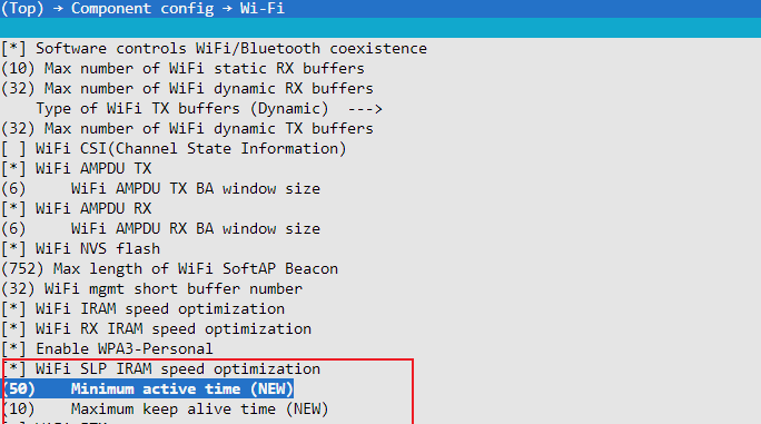
2.2.2 Change Minimum Wait Time and Maximum Keep-Alive Time
When the ESP32 operates as both STA and AP, it needs to wait for a period of time before turning off the RF after receiving data once, this time is called the Minimum active time, the default value is 50 ms. On the basis of ensuring the data throughput each time, this waiting time can be appropriately reduced to lower power consumption.
When the ESP32 is in power save mode, it needs to periodically send a keep alive packet to the AP to tell the AP that it is still connected. The Maximum keep alive time is the time period for sending this keep alive packet, the default is 10 s. Power consumption can be reduced by increasing this parameter to reduce packet sending.
Configuration item name:
ESP_WIFI_SLP_DEFAULT_MIN_ACTIVE_TIMEConfiguration path:
(Top) -> Component config -> Wi-Fi -> Wi-Fi SLP IRAM speed optimization -> Minimum active timeConfiguration item name:
ESP_WIFI_SLP_DEFAULT_MAX_ACTIVE_TIMEConfiguration path:
(Top) -> Component config -> Wi-Fi -> Wi-Fi SLP IRAM speed optimization -> Maximum keep alive time
Recommended configuration: Minimum active time = 15~20, Maximum keep alive time = 60.
2.2.3 Enable Power Management for Disconnection
After enabling this configuration item, the Modem sleep state can still be maintained when a disconnection occurs.

Configuration item name:
ESP_WIFI_STA_DISCONNECTED_PM_ENABLEConfiguration path:
(Top) → Component config → Wi-Fi → Power Management for station at disconnected
2.2.4 Enable Beacon Lost Optimization (only for release/v4.4 and above)
One of the basics of Wi-Fi keep alive is to be able to receive the beacon packet sent by the router on time. In actual use environment, various reasons can cause beacon loss. In versions prior to release/v4.4, after losing the beacon, the ESP32 will keep the RF on until the next beacon is received. Versions after 4.4 can avoid the impact of this behavior on power consumption by enabling beacon lost optimization.

Configuration item name:
ESP_WIFI_SLP_BEACON_LOST_OPTConfiguration path:
(Top) → Component config → Wi-Fi → Wifi sleep optimize when beacon lost
As shown in Figure 2-6, the optimization principle is that the RF receiver will not always be on when the beacon is lost. Instead, it will be turned on for a while and if no reception is received, it will go to sleep, then wake up to receive packets. If it still hasn’t received anything after repeating this process a few times, it will operate as usual, keeping the RF on until it receives a position. This can greatly improve the fault tolerance rate when the beacon is not received, thereby reducing power consumption.
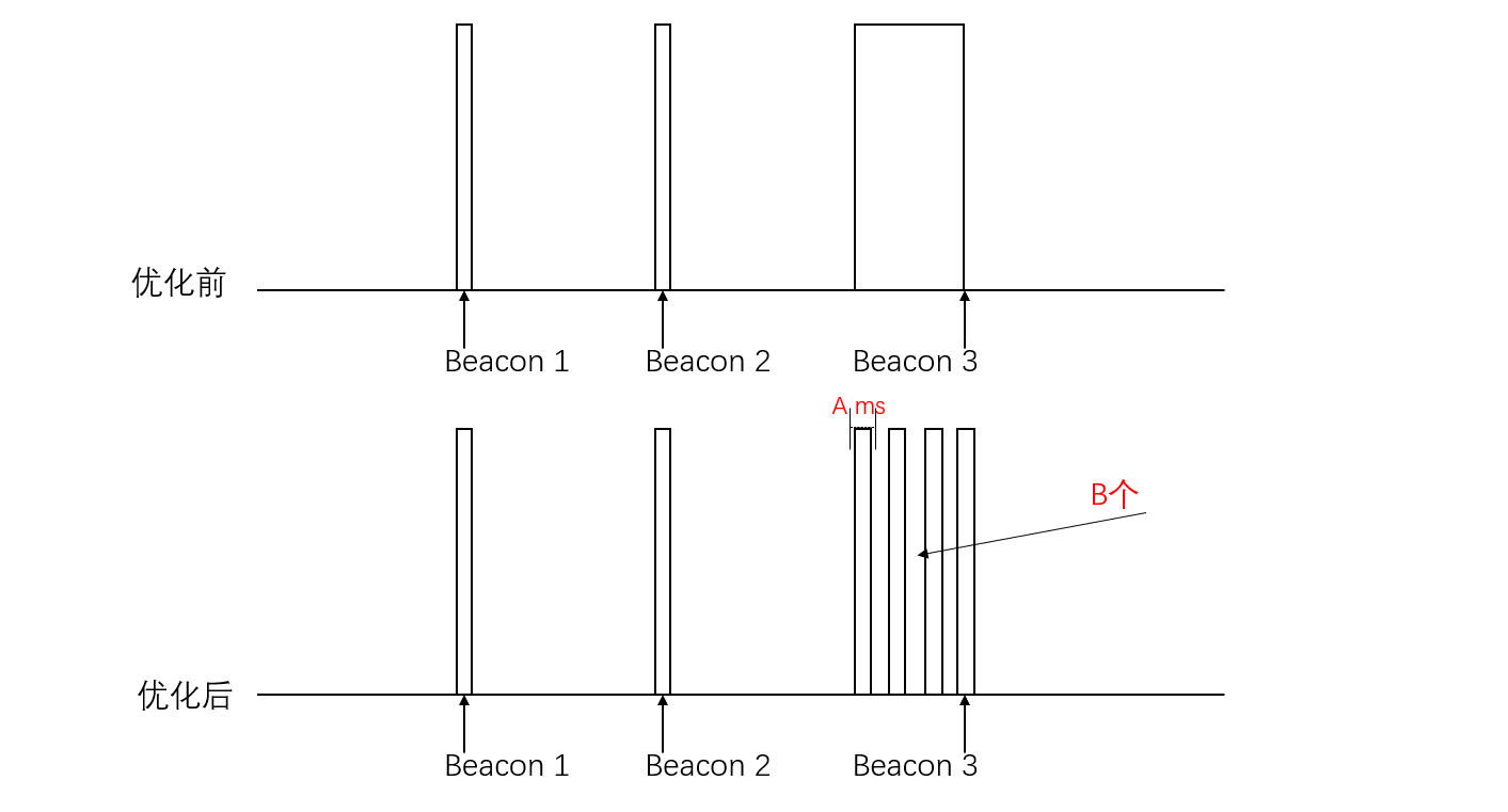
After enabling this option, four additional configuration items will be introduced, mainly focusing on the first two configuration items:
Option A: Beacon loss timeout indicates how long to wait without receiving a beacon before entering sleep mode.
Option B: Maximum number of consecutive lost beacons allowed indicates how many times to repeat without receiving before continuously turning on.
Note that option B should not be set too high, generally set to 3.
2.2.5 Reduce TX power
After enabling this option, the PHY TX power will be reduced after detecting a brownout reset, allowing the code to continue running.

Configuration item name:
ESP_PHY_REDUCE_TX_POWERConfiguration path:
(Top) → Component config → PHY → Reduce PHY TX power when brownout reset
2.2.6 Optimize Sleep IRAM Speed
Selecting this option will place the Wi-Fi library’s TBTT process and receive beacon function in IRAM. If this option is enabled, the average current of the Wi-Fi powersave mode will be reduced.

Configuration item name:
ESP_WIFI_SLP_IRAM_OPTConfiguration path:
(Top) → Component config → Wi-Fi → WiFi SLP IRAM speed optimization
2.2.7 Optimize IRAM Speed
All three of the following items can be enabled.
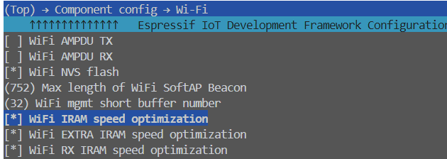
Configuration item name: -
ESP_WIFI_IRAM_OPT-ESP_WIFI_EXTRA_IRAM_OPT-ESP_WIFI_RX_IRAM_OPTConfiguration Path:
(Top) → Component config → Wi-Fi → WiFi IRAM speed optimization
2.2.8 Wi-Fi PHY Layer Packet Reception
An optional feature of ESP32-C6, during light sleep, the PHY layer automatically receives packets, Wi-Fi no longer needs CPU participation to receive beacons, only Wi-Fi MAC + Baseband + RF are working, to save power consumption.
Note
Supplementary content: T/RX waveform diagram under different modes

Configuration Item Name: -
ESP_WIFI_ENHANCED_LIGHT_SLEEP-ESP_WIFI_EXTRA_IRAM_OPT-ESP_WIFI_RX_IRAM_OPTConfiguration Path:
(Top) → Component config → Wi-Fi → WiFi modem automatically receives the beacon
3. Supplementary Content
3.1. The Difference Between DTIM and Listen Interval
When the chip establishes a connection as a STA with the router, it will be informed of the router’s DTIM, that is, how often the router will send a beacon. The STA needs to wake up at this time to receive the beacon and check if there is information that needs to be processed. The listen interval, on the other hand, is the STA telling the router how often it needs to wake up to receive the beacon, that is, the former is determined by the router, and the latter can be configured into the chip. The time interval is the value of DTIM or listen interval * 100 MS. If DTIM=10, the wake-up time interval is 10 * 100 ms = 1 s.
3.2. External 32KHz Crystal
Using an external 32KHz crystal can achieve lower power consumption. The main reasons are as follows:
The internal crystal is easily interfered with, while the external crystal has higher precision and can be used in various sleep situations.
For applications that require high time accuracy, such as Bluetooth and Wi-Fi keep-alive, it is necessary to wake up regularly to receive beacons. Once the clock drifts too much and misses the reception point, it will cause the RF waiting window to lengthen, thereby greatly increasing power consumption.
Enabling the external clock source requires the following configuration:

Configuration Item Name: -
ESP32C3_RTC_CLK_SRC_EXT_CRYS-ESP_WIFI_EXTRA_IRAM_OPT-ESP_WIFI_RX_IRAM_OPTConfiguration Path:
(Top) → Component config → ESP32XX-Specific → RTC clock source
There are two types of external crystals:
External 32kHz crystal: This is an external passive crystal, which is the crystal recommended most of the time
External 32kHz oscillator at 32K_XP pin: This is an external active crystal, which is more expensive and will cause the base current to rise by 50 ~ 100 μA
The ESP32-C2 only supports an external active crystal oscillator as it does not have an internal passive crystal oscillator circuit. The layout of the crystal oscillator can be referred to the hardware design guide corresponding to each chip.
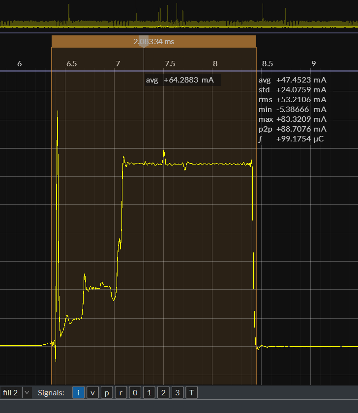
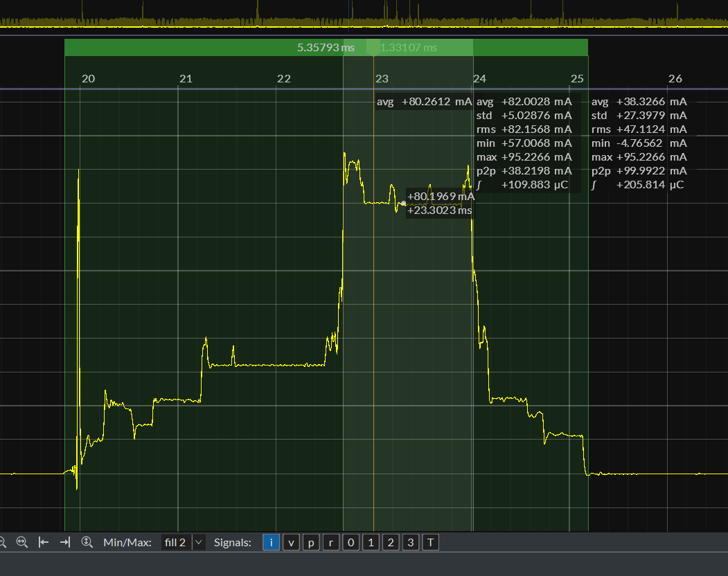
3.3. T/RX waveform under different modes
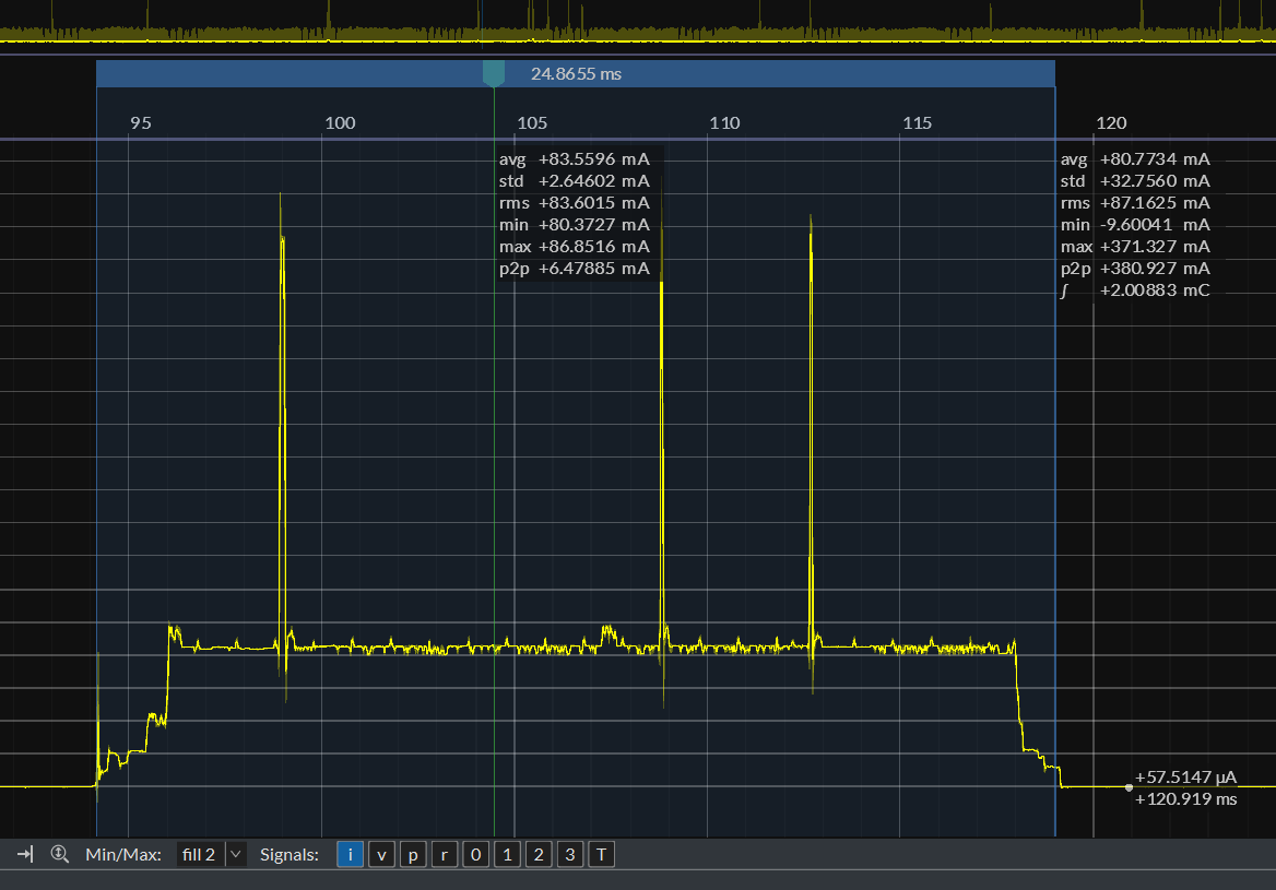
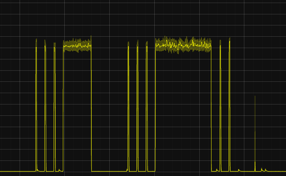
Modem Mode (Physical layer receives beacon): The time cost of receiving a packet once is about 2.1 ms, and the current of receiving a packet is about 64 mA ~ 70 mA.
Active Mode RX: The duration of receiving a packet once is about 5.3 ms, and the current of receiving a packet is about 80 mA.
RX without receiving a packet: Compared with the situation where no packet is received, there will be no current waveform lasting for a period of time.
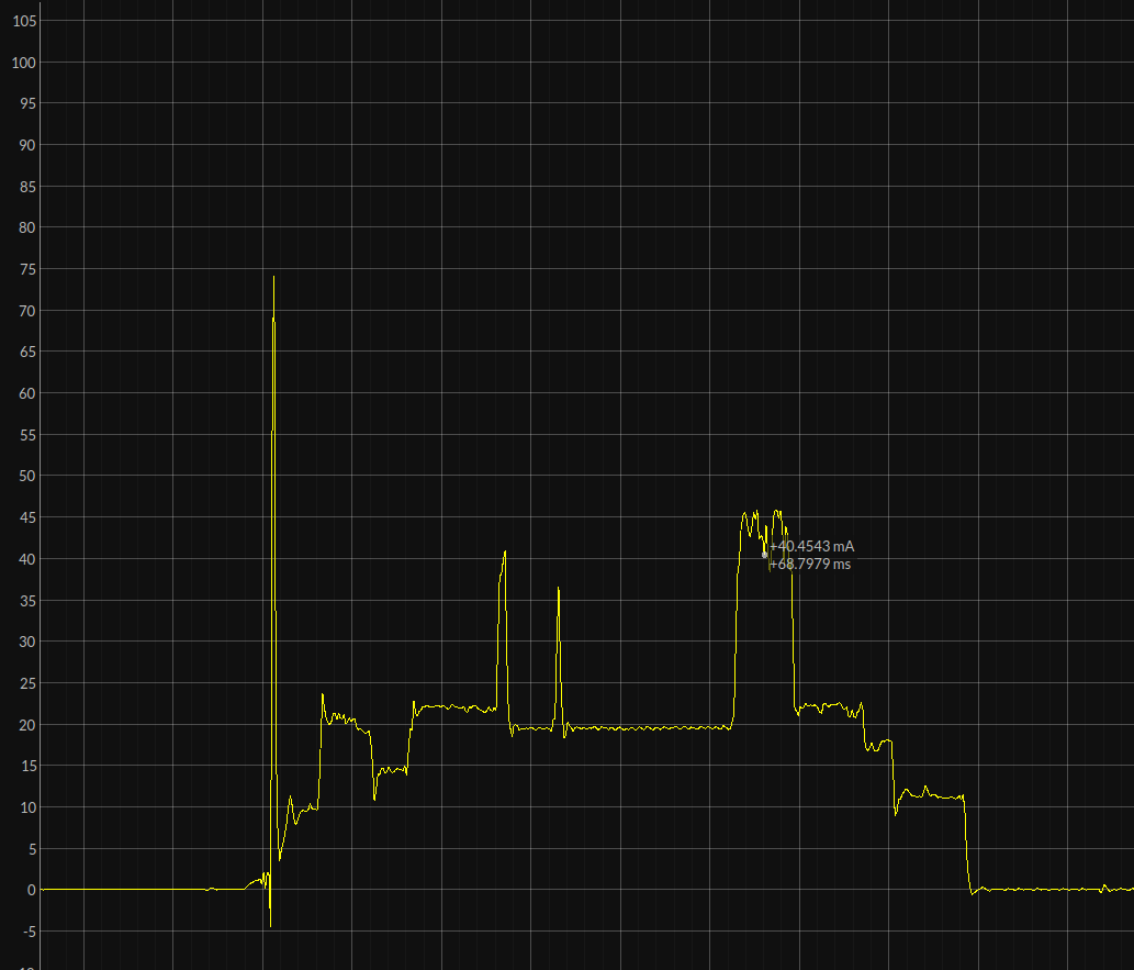
Active Mode TX: The duration is uncertain, and the TX current is related to the Wi-Fi channel.
