Watchdog
ESP Watchdog Timer Classification
Taking ESP32-C3 as an example, as follows:
- ESP32-C3
- Digital Watchdog Timer
Main System Watchdog Timer (MWDT0 & MWDT1)
RTC Watchdog Timer (RWDT)
- Analog Watchdog Timer
Super Watchdog (SWD)
Watchdog Trigger Principle
Taking ESP32-C3 as an example, it has two main system watchdog timers, namely MWDT0 and MWDT1. The digital watchdog will go through multiple stages during operation, and each stage can configure separate timeout time and timeout action. The existing logic is as follows:
The task watchdog uses MWDT0, the interrupt watchdog uses MWDT1, if ESP does not feed the dog in time, causing the watchdog timeout will trigger the watchdog interrupt.
Note
ESP32-C2 only has one timer group, so there is only one main system watchdog MWDT0, which is bound to the interrupt watchdog. At this time, the task watchdog is implemented using esp_timer.
Interrupt Watchdog
The interrupt watchdog is mainly used to detect scenarios where FreeRTOS cannot schedule tasks for a long time. In a real-time operating system, the task scheduling mechanism ensures that high-priority tasks that need real-time processing can quickly get the opportunity to execute, thereby avoiding long delays. If the system cannot normally schedule tasks, some critical tasks (such as Wi-Fi packet transmission and reception processing) may experience anomalies.
Working Principle
The interrupt watchdog uses the hardware watchdog timer of Timer Group 1, monitoring the system task scheduling status by adding a feed-dog operation in the SysTick interrupt. The SysTick interrupt is by default the lowest interrupt priority 1 in ESP-IDF, while the interrupt priority of the interrupt watchdog timer is 4, higher than the interrupt levels of most peripherals, and cannot be easily shielded by the system.
When the watchdog is not fed in the SysTick interrupt for a long time (default 300 ms), the interrupt watchdog interrupt will be triggered, the system will enter the interrupt watchdog exception handler, print register information, and crash.
Note
The interrupt disable operation will only turn off interrupts of priority 3 and below. In the Xtensa instruction set, interrupts of priority 4 and above can only be executed in assembly functions, therefore the interrupt watchdog cannot be masked by regular interrupt disable operations.

Interrupt Watchdog Working Principle Diagram
SysTick Timer (SysTick)
The SysTick timer is a system tick timer provided by the chip, featuring automatic reload and overflow interrupt functions. In RTOS, SysTick provides the necessary clock ticks for task scheduling, acting as the system’s “heartbeat”. Whenever a SysTick interrupt is triggered, the system performs a task switch.
The overflow interrupt interval can be adjusted by changing the tick value through the configuration item Component config -> FreeRTOS -> Tick rate. The default value is 100, which means a SysTick interrupt is triggered every 10 ms.
Warning
Too frequent SysTick interrupts can lead to frequent task scheduling, reducing system efficiency.
A too slow SysTick interrupt may cause task response delay
All time-related behaviors of the operating system are based on Tick, such as
vTaskDelay(100)delays 1 s when the Tick rate is 100, and only delays 100 ms when the Tick rate is 1000.
Trigger Reason
The fundamental reason for the triggering of the interrupt watchdog is that the SysTick interrupt cannot be executed normally, which mainly includes the following three situations:
Long-term Interruption Shutdown
The operation of disabling interrupts is used to protect program segments that cannot be interrupted midway, preventing the system from responding to interrupt requests. Long-term disabling of interrupts is the main cause of triggering the interrupt watchdog.
Common scenarios include:
Enter critical section (
portENTER_CRITICAL)Use spinlock
Other code segments that require interrupt protection
Blockage Exists in the Interrupt Service Routine
The Interrupt Service Routine (ISR) should adhere to the principle of rapid processing, transferring time-consuming operations to a non-interrupt environment for handling. If there is complex logic or blocking operations within the ISR, and it fails to exit before the interrupt watchdog times out, an exception will be triggered.
Frequently Asked Questions:
The ISR contains an infinite loop
Perform time-consuming operations in ISR
Call blocking function in ISR
Interrupt Flag Not Cleared
After the ISR (Interrupt Service Routine) is executed, the corresponding interrupt flag needs to be cleared. If it is not cleared correctly, the interrupt will continue to trigger, preventing the normal execution of the SysTick interrupt.
Note
The system often automatically clears the corresponding interrupt flag bit, so manual operation by the user is not required.
Configuration Options
The configuration related to the interrupt watchdog is located at Component config → ESP System Settings:
Interrupt watchdog: Enable or disable the interrupt watchdog function.Interrupt watchdog timeout (ms): Interrupt watchdog timeout duration, default is 300 ms.
Problem Analysis Method
When a watchdog interrupt exception is triggered, the system will stay at the location where the problem occurred. Analysis can be carried out in the following ways:
View Program Counter (PC) and Call Stack (Backtrace): Locate the problem code position
Check the context identifier in the crash information:
Includes
Core X was running in ISR contextindicates the problem occurred in the interrupt functionThe absence of this information usually indicates an issue caused by an interrupt, and the specific reason needs to be analyzed based on the location of the problem.
Practical Case Study Analysis
Issues with interrupt watchdog often combine with the FreeRTOS system in practical applications, manifesting in various forms. For a detailed analysis of actual cases and solutions, please refer to the Interrupt wdt timeout on CPU0/CPU1 section, which includes a complete problem analysis process and several typical examples.
Task Watchdog
The Task Watchdog is used to detect situations where a specific task occupies CPU resources for a long time. In the FreeRTOS preemptive kernel, high-priority tasks always get CPU resources first, which may cause low-priority tasks to be unable to execute for a long time. The Task Watchdog monitors the execution status of key tasks to ensure the correct manifestation of the system’s multitasking features.
Working Principle
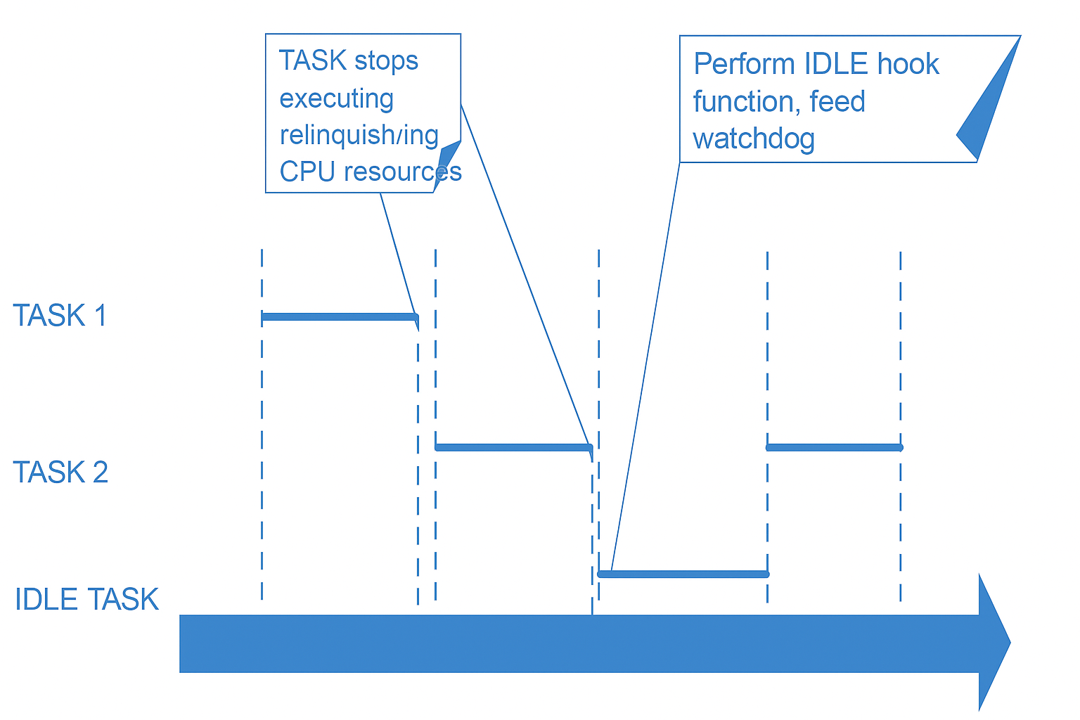
The task watchdog uses the hardware watchdog timer of Timer Group 0. By default, the system determines whether a watchdog event has occurred by monitoring the IDLE task. The IDLE task is the lowest priority system task in FreeRTOS. If this task can run normally, it indicates that other tasks have not occupied CPU resources for a long time.
When the system enters the IDLE task, it resets the watchdog timer through the hook function of the IDLE task. If it fails to enter the IDLE task for a long time, the watchdog will trigger a timeout.
Task Watchdog Working Principle Diagram
Monitoring Task Management
In addition to the default IDLE task monitoring, other tasks can also be added as monitoring targets:
Use
esp_task_wdt_add(NULL)to add the current task to the monitoring list.The monitored task must periodically call
esp_task_wdt_reset()for watchdog feeding operations.The system requires all monitored tasks to complete the watchdog feeding before it will reset the watchdog timer.
Configuration Options
The configuration related to the task watchdog is located at Component config → ESP System Settings:
Initialize Task Watchdog Timer on startup: Enable or disable the task watchdog.Invoke panic handler on Task Watchdog timeout: Set whether to restart the system when the watchdog is triggeredTask Watchdog timeout period (seconds): The timeout period for the task watchdog, default is 5 seconds.Watch CPU0 Idle Task: Monitor the IDLE task of CPU0 (In a dual-core system, you can choose whether to monitor CPU1)
Problem Diagnosis
Basic Diagnosis
When the task watchdog is triggered, the system will print relevant information, including:
The task currently running
Relevant call stack information
Advanced Diagnostics
For complex applications, you can use the vTaskGetRunTimeStats() interface to analyze CPU usage:
Enable relevant configurations:
Component config -> FreeRTOS -> Enable FreeRTOS trace facilityComponent config -> FreeRTOS -> Enable FreeRTOS stats formatting functionsComponent config -> FreeRTOS -> Enable FreeRTOS to collect run time stats
Loop call to the statistical interface:
void run_time_monitor(void)
{
    char *pbuffer = (char *)calloc(1, 2048);
    printf("----------------------------------------------\r\n");
    vTaskGetRunTimeStats(pbuffer);
    printf("%s", pbuffer);
    printf("----------------------------------------------\r\n");
    free(pbuffer);
}
Note
When using the vTaskGetRunTimeStats interface, you need to disable the Invoke panic handler on Task Watchdog timeout configuration, otherwise the system will restart due to watchdog triggering, and it will not be able to print statistical information.
Solution
Code Optimization Strategy
For tasks that indeed have issues:
Use blocking interfaces with timeouts in the loop, such as
xSemaphoreTake()(the timeout cannot be 0)Use
vTaskDelay()to actively yield CPU resourcesOptimize algorithm, reduce single execution time
For normal high-load tasks (without wishing to reduce operational efficiency):
Manually add a watchdog operation in high-load tasks
Manual Watchdog Operation
For tasks that need to run for a long time, you can use the manual watchdog feeding method:
static void long_running_task(void* arg)
{
    // Remove watchdog monitoring of IDLE task
    esp_task_wdt_delete(xTaskGetIdleTaskHandleForCPU(0));
    // Add the current task to the monitoring list
    esp_task_wdt_add(NULL);

    while (1) {
        // Execute time-consuming operations

        // Feed the dog regularly
        esp_task_wdt_reset();
    }

    // Restore IDLE task monitoring when the task ends
    esp_task_wdt_delete(NULL);
    esp_task_wdt_add(xTaskGetIdleTaskHandleForCPU(0));
}
Warning
The manual watchdog feeding operation is relatively complex, as ESP-IDF requires all monitored tasks to complete the watchdog feeding before the watchdog timer is reset. It is not recommended to arbitrarily modify the internal implementation of ESP-IDF.
TimerGroup Watchdog
Common LOG:
1. rst:0x8 (TG1WDT_SYS_RST),boot:0xc (SPI_FAST_FLASH_BOOT)
2. rst:0x7 (TG0WDT_SYS_RST),boot:0xc (SPI_FAST_FLASH_BOOT)
Trigger conditions:
Task interrupts and task scheduling cannot be triggered normally, it can be considered that there is an exception in CPU operation
Possible reasons:
CPU instruction fetching is abnormal, at this time suspect whether there is hardware interference in Flash or PSRAM communication, such as abnormal occupation of Flash or PSRAM pins, high frequency interference, etc.
Unstable power supply
Possible wild pointer problem
RTC Watchdog
Common LOG:
rst:0x10 (RTCWDT_RTC_RESET),boot:0x13 (SPI_FAST_FLASH_BOOT)
Features:
In addition to resetting digital peripherals, it also resets the RTC module
Can be called in the program
Stages that can trigger the RTC watchdog:
Boot stage: This watchdog needs to be enabled at this stage through the CONFIG_BOOTLOADER_WDT_ENABLE option
Restart stage
Panic Stage
Enter the light sleep stage, after entering light sleep, the hardware will automatically turn off the RTC watchdog
Other watchdogs
External hardware watchdog
The user may encounter the following abnormal scenarios:
The hardware has unstable power supply
Occasionally, the chip hangs without triggering any reset
In this case, it is recommended to connect an external hardware watchdog, which can be fed by periodically flipping the GPIO through the software program, to avoid the situation where the ESP chip is always hanging.