DVP & MIPI-CSI Camera Solution Introduction
Note
This document is automatically translated using AI. Please excuse any detailed errors. The official English version is still in progress.
Common Application Scenarios
Existing video demos
ESP32-S3 Blazing Milliseconds [High Frame Rate 125 fps]: ESP32-S3 with global shutter camera, achieving high frame rate of 125 FPS. It can capture the motion trajectory of moving objects, such as high frame rate image capture for writing pens and other scenarios. Combined with ESP32-S3’s network capabilities, it’s the first choice for IoT smart camera solutions.
ESP32-S3 Watching Cute Cats Eating [High Resolution]: ESP32-S3-EYE AI development board with a 2MP camera. High-resolution real-time viewing of cats eating, first choice for pet monitoring.
Product barcode scanning, train ticket scanning, tax invoice scanning, resource scanning and downloading, etc.
Auto focus + Internet
Photos taken are immediately refreshed on webpages or displayed on LCD
Scanner, smart car auxiliary navigation
Face recognition
Technology or system for identity confirmation or identity search through facial recognition
Video surveillance, light-sensitive ambient lighting
AI applications
Gesture recognition
Number recognition
Food recognition
Posture detection
Reference Materials
Software references
Camera driver library: You can refer to esp32-camera, which is Espressif’s camera driver library providing camera peripheral drivers for ESP32/ESP32-S2/ESP32-S3, including the underlying 8-bit DVP interface driver, sensor driver, and image encoding/decoding. ESP32-P4, in addition to supporting the DVP interface, also supports the MIPI CSI interface. This chip uses a new code architecture, which you can refer to in esp-video-components.
Related modules/development boards purchase
Module/development board materials and selection reference
Performance Test Data Appendix
Camera solutions primarily focus on the following performance indicators:
Sensor initialization time (especially for projects that need to capture immediately after startup)
Supported resolutions and data formats
Frame rate under specified resolution and data format
Transmission rate when used with Wi-Fi
Supported image processing functions (currently mainly JPEG encoding/decoding performed through software)
Related test code can be found in the test examples.
Sensor Initialization Time
Sensor |
Init time (ms) |
|---|---|
OV3660, JPEG |
604 |
OV3660, RGB565 |
1301 |
OV2640, JPEG |
200 |
OV5640, JPEG |
240 |
Note
When conducting the above tests, please note:
A picture needs to be captured at the end of the test to verify correctness
You can refer to More optimization methods to optimize the system configuration as much as possible.
Supported Resolutions and Data Formats
The supported resolution size depends entirely on the camera’s maximum performance, but the capabilities of DVP itself and CPU DMA are limited, and excessive resolution will put pressure on data transmission:
If the DVP camera sensor can output JPEG type images, the recommended maximum resolution should not exceed 5MP
If the DVP camera sensor cannot output JPEG type images (when the image type is YUV422/RGB565, etc.), the recommended maximum resolution should not exceed 1MP
Data formats mainly depend on the output formats supported by the camera. These primarily include:
RGB
YUV
JPEG
RAW Data
BMP
Only Y/Grayscale
When the camera itself does not support JPEG data output, ESP32 can perform JPEG compression to output JPEG data.
Note
Specifically, when requiring resolutions exceeding 1024*720, it’s best to consider cameras that support JPEG encoding. It should be noted that JPEG encoding/decoding performed by ESP32 will put pressure on CPU and memory.
For the ESP32P4’s MIPI CSI interface, it supports data in RGB, YUV, and RAW Data formats.
Frame Rate Under Specified Resolution and Data Format
Output format |
Chip model |
Sensor model |
Resolution |
Frame rate |
|---|---|---|---|---|
YUV422RGB565 |
ESP32-S3 |
SC030IOT(DVP) |
640*480 |
30 fps |
JPEG |
ESP32S3 |
OV5640(DVP) |
1600*1200 |
25 fps |
Only Y/MONO |
ESP32-S3/ESP32-S2 |
SC031GS(DVP) |
240*240 |
125 fps |
RGB RAW |
ESP32-P4 |
SC2336(MIPI) |
1920*1080 |
30 fps |
RGB565 |
ESP32-P4 |
OV5645(MIPI) |
2592*1944 |
15 fps |
YUV422 |
ESP32-P4 |
SC101IOT(DVP) |
1280*720 |
24 fps |
YUV422 |
ESP32-P4 |
SC035HGS(MIPI) |
640*480 |
100 fps |
YUV422 |
ESP32-P4 |
BF3901(SPI 1-Bit) |
240*320 |
10 fps |
The rates of different cameras vary greatly. When testing JPEG rates, you should specify the JPEG compression parameters and try to shoot colorful pictures. Shooting monochrome objects will contain more low-frequency information, resulting in smaller data volume after JPEG compression, and the generated data will not be representative.
For esp32-camera, the frame rate of the same camera varies greatly when settings for data format, resolution, main clock XCLK size, and idle interval time parameters differ. To ensure frame rate, fb_count should not be less than 2 when initializing the camera. Currently, driver parameters for most cameras are not optimal, and configuration methods for different cameras are not standardized, so there is significant room for optimization of the above performance data. ESP32-S3 has an independent CAM DVP interface with a peripheral interface rate 2-3 times higher than ESP32.
Transmission Rate When Used With Wi-Fi
Usually, once the user’s required data format, resolution, frame rate and other parameters are determined, the feasibility of the solution can be initially estimated based on Wi-Fi test data.
Taking JPEG@480*320@20fps as an example, a single JPEG@480*320 image is typically 30KB-50KB. With a required frame rate of 20fps, the required Wi-Fi speed should be 600KB/s-1000KB/s. By checking the ESP32-S3 Wi-Fi throughput, it can be seen that ESP32-S3 meets these requirements.
Current testing of the esp-rtsp example running on ESP32-S3 shows that 720p + MJPEG video stream can achieve a frame rate of around 20fps.
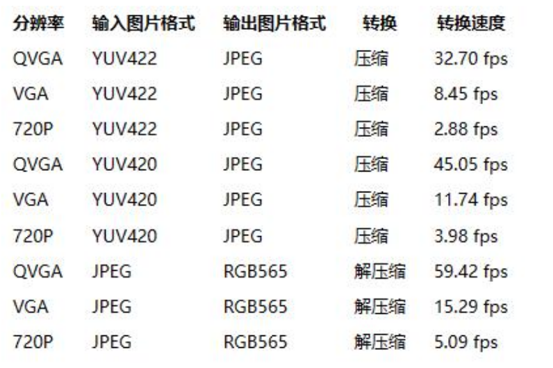
ESP32-S3 Encoding/Decoding Performance
ESP32-S3 does not have hardware encoding/decoding capabilities; its driver code includes the TinyJPEG software encoding component.
Common Q&A
Querying resolution and output format descriptions in esp-video.
esp-video provides detailed descriptions of camera sensor output formats. Taking OV5645 as an example, users can refer to this description to understand its supported output formats and select the desired output format in menuconfig. If you’re using ESP32-P4 and encounter unsupported resolutions, you can use the PPA module to scale or crop the original output image.
Modifying ESP32-P4 ISP parameters.
For sensors outputting RAW format data, the ISP module is needed to optimize image brightness and color. The ISP system consists of three parts: ISP calibration tools, ISP control algorithms, and ISP hardware pipelines. The ISP calibration tools require specialized laboratories and professional personnel to use. Some parameters of the ISP control algorithms and ISP module can be configured through JSON files. Taking OV2710 as an example, its JSON file is located here. Users can copy this default JSON file to create custom JSON files and specify the path to this file through the configuration menu.
How to determine if a sensor requires enabling the ISP Pipelines Controller?
This requires checking the sensor’s datasheet. Based on output characteristics, sensors can be divided into three types:
JPEG sensor: Sensors that can directly output JPEG data. The internal structure of these sensors can be simplified as: RAW sensor + Internal ISP + JPEG encoder. The Internal ISP encodes RAW data into YUV or RGB format data; the JPEG encoder encodes RGB or YUV format data into JPEG. It actually has three modules working.
YUV sensor: Sensors that can directly output YUV422 or RGB565 data. The internal structure of these sensors can be simplified as: RAW sensor + Internal ISP. It actually has two modules working. When JPEG data is needed, the SOC needs to perform JPEG encoding. For ESP32-S3, the esp_new_jpeg component can be used for software encoding. For ESP32-P4, it has a HW_JPEG_Encoder.
RAW sensor: Sensors that can only output RAW8 or RAW10 data. The internal structure of these sensors only has a RAW sensor. Therefore, when projects need RGB, YUV, or JPEG format data, the SOC needs to deploy ISP and JPEG encoder. For projects with low efficiency requirements, software-implemented ISP can be used; otherwise, it’s necessary to enable the ISP Pipelines Controller on the SOC.
For RAW sensors, how to quickly obtain JPEG images or H.264 data?
First, enable the ISP Pipelines Controller on the SOC to obtain YUV or RGB format data in the ISP output queue. Then use the M2M (MemoryToMemory) middleware provided by esp-video to transfer data from the ISP output queue to the encoder input queue. Finally, retrieve the encoded data from the encoder output queue. Examples using the M2M mechanism include: image_storage and uvc.
What to do if the image frame rate is slow?
The image data users care about is often processed and transmitted through multiple modules. Therefore, it’s necessary to guide customers to test the rate at each stage step by step.
First, confirm the actual output frame rate of the camera sensor. For users using esp32-camera, use the test_framerate example; for users using esp-video, use the capture_stream example. Then gradually enable ISP and encoder, and test the rate after enabling these encoding modules respectively. Finally, test the data transmission rate (network, peripheral interface).
How to test the functionality of the HDMI to MIPI-CSI bridge sensor?
The data flow of the HDMI to MIPI-CSI bridge can be described as HDMI output device -> HDMI to MIPI-CSI bridge -> ESP32 MIPI RX. This solution mainly provides a method to seamlessly integrate the HDMI video stream into various applications. Users first connect the various modules, then compile and burn the examples in esp-video/examples. Finally, configure the output format of the HDMI output device to be the same as the format selected in the example, and you can execute the test program.