Wi-Fi Signaling Test
The Wi-Fi Signaling Test assesses and verifies the Wi-Fi signaling functions of wireless network devices, focusing on stable and reliable communication across varying operating scenarios. It evaluates Over-The-Air (OTA) performance, including Total Radiated Power (TRP) and Total Isotropic Sensitivity (TIS).
Set Up Test Environment
UART Connection Description
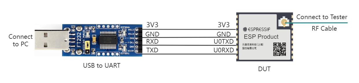
The Device Under Test (DUT) is a product designed based on Espressif chips or modules. The device under test is connected to the USB-to-UART adapter board via UART.
Note
The CHIP_EN pin of the device under test is pulled up by default. If it is not pulled up in the product design, you need to manually connect the CHIP_EN to the 3V3 pin.
Some serial communication boards have already swapped RXD and TXD internally, so there is no need to reverse them. The wiring needs to be adjusted according to the actual situation.
Espressif chips have a power-on self-calibration feature. Therefore, before powering on the device under test, the RF connection cable must be connected to the testing instrument.
Flash Firmware
Open DownloadTool.
Set
ChipType,Com PortandBaud Rate, clickOpen, and select download toFlash.ESP32-S3 Wi-Fi Signaling Test Firmware (Single Country) supports a single country code, ESP32-S3 Wi-Fi Signaling Test Firmware (Multiple Countries) supports multiple country codes. They each include 4 bin files, i.e., bootloader.bin, partition-table.bin, phy_init_data.bin, and ssc.bin.
After unzipping ESP32-S3 Wi-Fi Signaling Test Firmware (Single Country) or ESP32-S3 Wi-Fi Signaling Test Firmware (Multiple Countries), flash the 4 bin files to the following addresses via UART.
bin file |
flashing address |
|---|---|
bootloader.bin |
0x0 |
partition-table.bin |
0x8000 |
phy_init_data.bin |
0xF000 |
ssc.bin |
0x10000 |
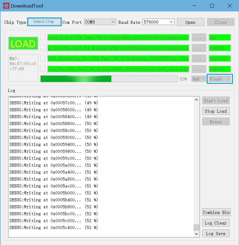
Firmware Flashing Schematic
After the flashing is completed, continue with the following steps for signaling testing.
Start Testing
Check Power-on Log
Note
BaudRate is set to 115200.
Use a serial communication tool, such as Friendly Serial Assistant, to configure the port number and baud rate. After the device under test is powered on again, if the serial output is similar to the following information, you can confirm that the test status is normal:
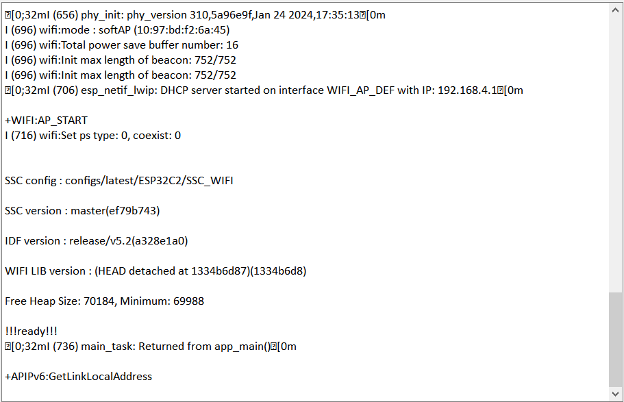
Serial Port Log for Device Power-on
Device Provisioning
Enter the following two commands in the serial port in sequence for network configuration.
//Device Provisioning
//Configure the prototype to enter station mode
op -S -o 1

//Connect to AP, SSID is CMW-AP, password is 12345678
sta -C -s CMW-AP -p 12345678
Note
The -p parameter is used to set the AP password. If the AP has no password, this parameter is not needed.
After the station device is assigned an IP address, the Wi-Fi connection is successful, and the following log is printed:
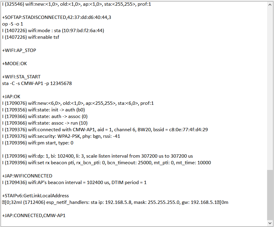
Serial Port Log for Device Provisioning
After the device under test is successfully connected, you can use the RF test instrument for Wi-Fi Signaling Test.