ESP32-C3-LCDkit
This user guide will help you get started with ESP32-C3-LCDkit and will also provide more in-depth information.
The document consists of the following sections:
Board Overview: Overview of the board hardware/software.
Start Application Development: How to set up hardware/software to develop applications.
Hardware Reference: More detailed information about the board’s hardware.
Hardware Revision Details: This is the first revision of this board released.
Sample Request: How to get a sample board.
Related Documents: Links to related documentation.
Disclaimer and Copyright Notice: Link to the disclaimer and copyright notice.
Board Overview
ESP32-C3-LCDkit is an ESP32-C3-based evaluation development board with an SPI interface display. It also has an integrated rotary encoder switch and features screen interaction. Due to its low cost, low power consumption, and high performance, ESP32-C3 satisfies the basic GUI interaction needs, gaining ground in scenarios with small screen sizes.

ESP32-C3-LCDkit with ESP32-C3-MINI-1 Module
Feature List
The main features of the board are listed below:
Module Embedded: ESP32-C3-MINI-1 module with 4 MB flash and 400 KB SRAM
Display: Compatibility with various subboards and support for displays with
I2CandSPIinterfaces. Please refer to LCD Subboards for more informationRotary Encoder Switch: Key switches and 360° rotation for on-screen GUI control
Infrared module: Infrared transmitter and infrared receiver for infrared wireless control
Audio: On-board audio amplifier and speaker for audio playback
USB: USB Type-C download/debug
Block Diagram
The block diagram below shows the components of ESP32-C3-LCDkit and their interconnections.
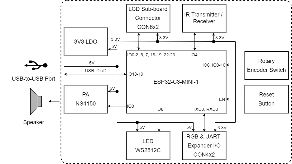
ESP32-C3-LCDkit Block Diagram (Click to Enlarge)
Description of Components
ESP32-C3-LCDkit is a development board designed for wildlife protection. It contains a mainboard and a subboard.
Mainboard
ESP32-C3-LCDkit_MB is the core of the kit, which integrates the ESP32-C3-MINI-1 module and provides ports for connection to the LCD subboard.
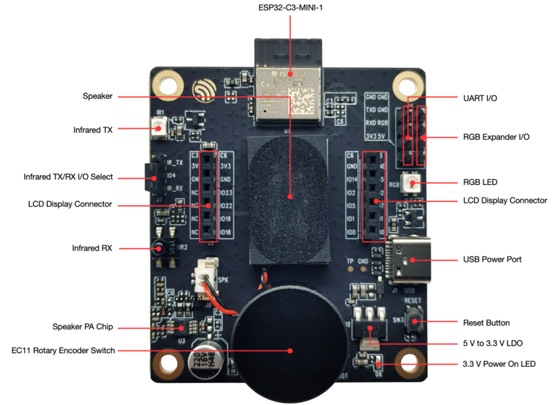
ESP32-C3-LCDkit - Front (Click to Enlarge)
The key components of the board are described in a clockwise direction.
Key Component |
Description |
|---|---|
ESP32-C3-MINI-1 Module |
ESP32-C3-MINI-1 is a generic Wi-Fi + Bluetooth LE MCU module that is built around the ESP32-C3 series of SoCs. It is integrated with 4 MB flash and 400 KB SRAM. |
UART & RGB Expander I/O |
Connects the system power supply pins and UART and RGB data pins via a 2.54 mm pitch pin header. |
RGB LED |
Supports configuring the RGB LED display to indicate status or behavior. |
Speaker |
Supports speaker playback through an audio power amplifier. |
LCD Display Connector |
Connects the 1.28” LCD subboard via a 2.54 mm pitch female header. |
USB Power Port |
Provides power to the entire system. It is recommended to use at least a 5V/2A power adapter to ensure a stable power supply. Used for USB communication between the PC side and the ESP32-C3-MINI-1 module. |
Reset Button |
Press this button to reset the system. |
5 V to 3.3 V LDO |
Low Dropout Regulator (LDO). |
3.3 V Power On LED |
Indicates the status of the system power supply. |
EC11 Rotary Encoder Switch |
Features both a 360° rotary encoder and a key switch to enable control of the on-screen GUI. |
Speaker PA Chip |
Supports speaker playback. |
Infrared RX |
Receives external infrared signals. |
Infrared TX/RX I/O Select |
Select the infrared RX/TX function via a 2.54 mm pitch pin header and jumper caps. |
Infrared TX |
Sends out infrared signals. |
LCD Subboards
The ESP32-C3-LCDkit_DB subboard supports a 1.28” LCD screen with SPI interface and 240x240 resolution. The driver chip used for this screen is GC9A01.
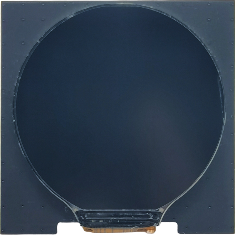
ESP32-C3-LCDkit_DB - Front (Click to Enlarge)
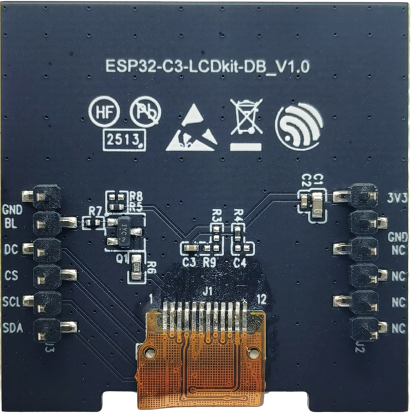
ESP32-C3-LCDkit_DB - Back (Click to Enlarge)
Software Support
The ESP32-C3-LCDkit development framework is ESP-IDF. ESP-IDF is a FreeRTOS-based SoC development framework with a bunch of components including LCD, ADC, RMT, and SPI. An example is provided for ESP32-C3-LCDkit under the folder Examples . You can configure project options by entering idf.py menuconfig in the example directory.
Application Examples
The following application examples are available for ESP32-C3-LCDkit:
Knob Panel Example - Demonstrates a GUI demo for a knob panel with voice playback functionality, providing a reference for developing similar applications using the ESP32-C3-LCDkit.
For more examples and the latest updates, please refer to the examples folder.
To explore the application examples or to develop your own, please follow the steps outlined in the Start Application Development section.
Start Application Development
This section provides instructions on how to do hardware and software setup and flash firmware onto the board to develop your own application.
Required Hardware
1 x ESP32-C3-LCDkit_MB
1 x LCD subboard
1 x USB 2.0 cable (standard Type-A to Type-C)
1 x PC (Windows, Linux, or macOS)
Note
Please make sure to use the appropriate USB cable. Some cables can only be used for charging, not for data transfer or program flashing.
Hardware Setup
Prepare the board for loading of the first sample application:
Connect the LCD subboard to the LCD Display Connector.
Plug in the USB cable to connect the PC with the board.
The LCD lights up and you can now control GUI through the rotary encoder switch.
Now the board is ready for software setup.
Software Setup
To learn how to quickly set up your development environment, please go to Get Started > Installation.
For more software information on developing applications, please go to Software Support.
Hardware Reference
This section provides more detailed information about the board’s hardware.
GPIO Allocation
The table below provides the allocation of GPIOs exposed on terminals of ESP32-C3-MINI-1 module to control specific components or functions of the board.
Pin |
Pin Name |
Function |
|---|---|---|
1 |
GND |
Ground |
2 |
GND |
Ground |
3 |
3V3 |
3.3 V power supply |
4 |
NC |
No connection |
5 |
IO2 |
LCD_D/C |
6 |
IO3 |
AUDIO_PA |
7 |
NC |
No connection |
8 |
EN |
Reset |
9 |
NC |
No connection |
10 |
NC |
No connection |
11 |
GND |
Ground |
12 |
IO0 |
LCD_SDA |
13 |
IO1 |
LCD_SCL |
14 |
GND |
Ground |
15 |
NC |
No connection |
16 |
IO10 |
ENCODER_A |
17 |
NC |
No connection |
18 |
IO4 |
IR_RX/IR_TX |
19 |
IO5 |
LCD_BL_CTRL |
20 |
IO6 |
ENCODER_B |
21 |
IO7 |
LCD_CS |
22 |
IO8 |
RGB_LED |
23 |
IO9 |
ENCODER_SW |
24 |
NC |
No connection |
25 |
NC |
No connection |
26 |
IO18 |
USB_DN |
27 |
IO19 |
USB_DP |
28 |
NC |
No connection |
29 |
NC |
No connection |
30 |
RXD0 |
Reserved |
31 |
TXD0 |
Reserved |
32-35 |
NC |
No connection |
36-53 |
GND |
Ground |
Power Distribution
The development board is powered via the USB-to-USB port:
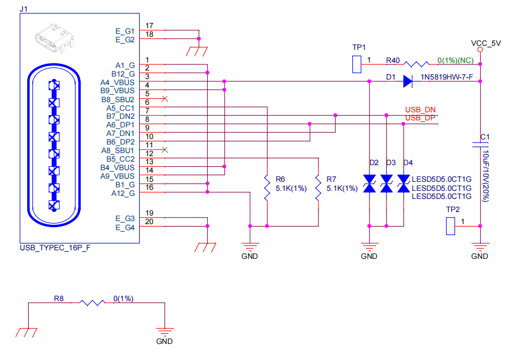
ESP32-C3-LCDkit - USB-to-USB Power Supply
Output system power supply:

ESP32-C3-LCDkit - System Power Supply
Infrared TX/RX Select
Since the Infrared TX and Infrared RX modules share the same signal line on the chip, it is required to short-circuit specific pins in Infrared TX/RX Select Port via jumper caps to choose between the TX/RX function:
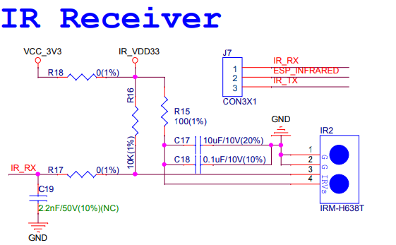
ESP32-C3-LCDkit - Infrared RX Module
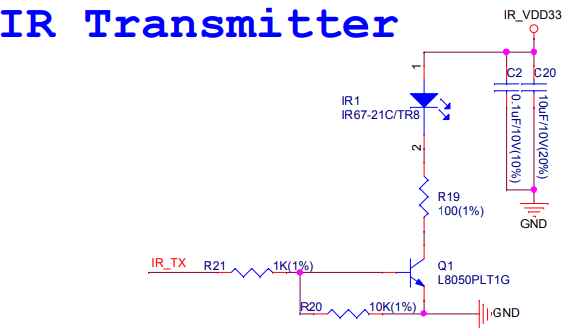
ESP32-C3-LCDkit - Infrared TX Module
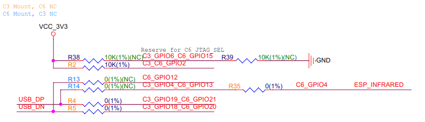
C6 Module Compatibility Design
ESP32-C3-LCDkit development board uses the ESP32-C3-MINI-1 module by default, with resistors R2, R4, R5, and R35 connected to the mainboard:
ESP32-C3-LCDkit - C3/C6 Resistor Settings
The development board is also designed to be compatible with the ESP32-C6-MINI-1 module, where resistors R2, R4, R5, and R35 need to be removed and resistors R13 and R14 need to be connected.
Hardware Setup Options
Automatic Download
After the development board is powered on, press the rotary encoder switch and Reset button, then release Reset first and the encoder second, to put the ESP development board into download mode.
Hardware Revision Details
ESP32-C3-LCD-Ev-Board: This older-version board is an engineering sample and is minimally maintained by Espressif. For historical documentation for this board, please refer to ESP32-C3-LCD-Ev-Board User Guide.
Sample Request
ESP32-C3 is a cost-effective and industry-leading low-power performance solution for building rotary or small displays driven by an SPI interface. For sample requests, please contact us at sales@espressif.com.