ESP32-C3-LCD-Ev-Board
This user guide will help you get started with ESP32-C3-LCD-Ev-Board and will also provide more in-depth information.
The document consists of the following sections:
Board Overview: Overview of the board hardware/software.
Start Application Development: How to set up hardware/software to develop applications.
Hardware Reference: More detailed information about the board’s hardware.
Hardware Revision Details: This is the first revision of this board released.
Sample Request: How to get a sample board.
Related Documents: Links to related documentation.
Board Overview
ESP32-C3-LCD-Ev-Board is an ESP32-C3-based evaluation development board with an SPI interface display. It also has an integrated rotary encoder switch and features screen interaction. Due to its low cost, low power consumption, and high performance, ESP32-C3 satisfies the basic GUI interaction needs, gaining ground in scenarios with small screen sizes.
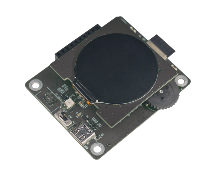
ESP32-C3-LCD-Ev-Board with ESP32-C3-MINI-1 Module
Feature List
The main features of the board are listed below:
Module Embedded: ESP32-C3-MINI-1 module with 4 MB flash and 400 KB SRAM
Display: Compatibility with various subboards and support for displays with
I2CandSPIinterfaces. Please refer to LCD Subboards for more informationRotary Encoder Switch: Key switches and 360° rotation for on-screen GUI control
USB: USB Type-C download/debug
Block Diagram
The block diagram below shows the components of ESP32-C3-LCD-Ev-Board and their interconnections.
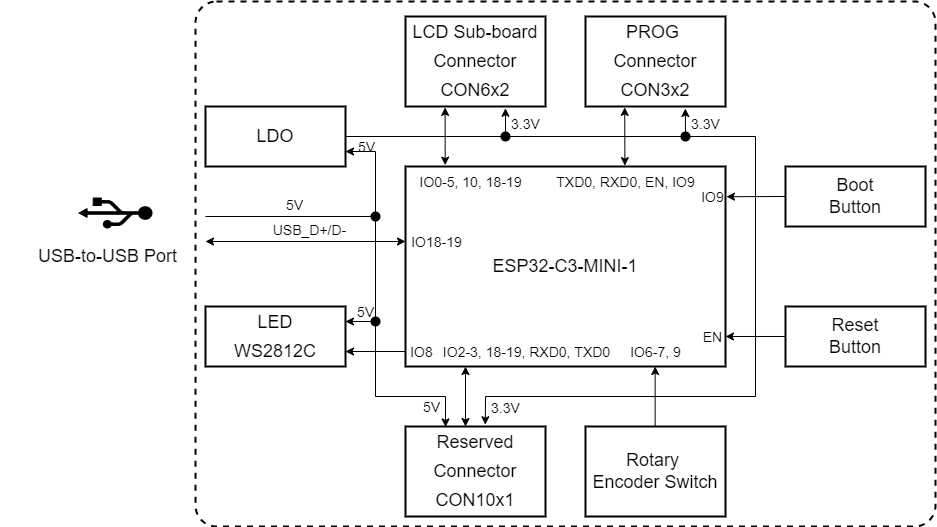
ESP32-C3-LCD-Ev-Board Block Diagram (Click to Enlarge)
Description of Components
The ESP32-C3-LCD-Ev-Board development board consists of a mainboard and a subboard.
Mainboard
ESP32-C3-LCD-Ev-Board_MB is the core of the kit, which integrates the ESP32-C3-MINI-1 module and provides ports for connection to the LCD subboard.
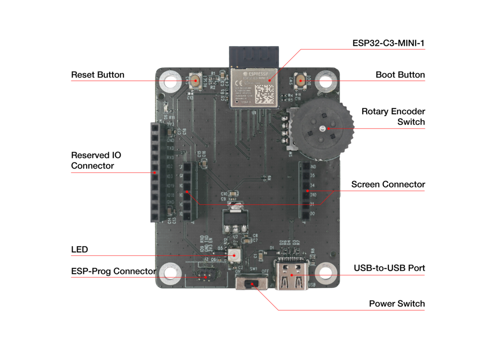
ESP32-C3-LCD-Ev-Board - Front (Click to Enlarge)
The key components of the board are described in a counter-clockwise direction.
Key Component |
Description |
|---|---|
ESP32-C3-MINI-1 Module |
ESP32-C3-MINI-1 is a generic Wi-Fi + Bluetooth LE MCU module that is built around the ESP32-C3 series of SoCs. It is integrated with 4 MB flash and 400 KB SRAM. |
Reset Button |
Press this button to reset the system. |
Reserved IO Connector |
Connects the system power supply pins and some reserved module pins via a 2.54 mm pitch connector. |
LED |
Supports configuring the RGB LED display to indicate status or behavior. |
ESP-Prog Connector |
Connects the Program interface of ESP-Prog for firmware download and debugging via a 1.27 mm pitch connector. |
Power Switch |
Power Toggle ON/OFF: Toggle ON to power on the board and OFF to power off the board. |
USB-to-USB Port |
Provides power to the entire system. It is recommended to use at least a 5V/2A power adapter to ensure a stable power supply. Used for USB communication between the PC side and the ESP32-C3-MINI-1 module. |
Screen Connector |
Connects the 1.28” LCD subboard via a 2.54 mm pitch connector. |
Rotary Encoder Switch |
Features both a 360° rotary encoder and a key switch to enable control of the on-screen GUI. |
Boot Button |
Holding down the Boot key and momentarily pressing the Reset key initiates the firmware upload mode. Then you can upload firmware through the serial port or USB. |
LCD Subboards
The ESP32-C3-LCD-Ev-Board_DB subboard supports a 1.28” LCD screen with SPI interface and 240x240 resolution. The driver chip used for this screen is GC9A01.
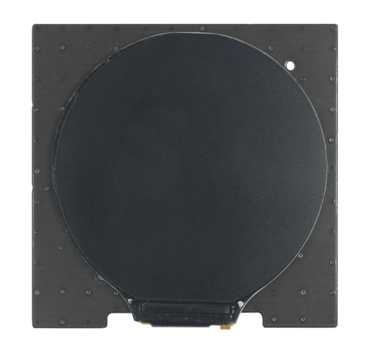
ESP32-C3-LCD-Ev-Board_DB - Front (Click to Enlarge)
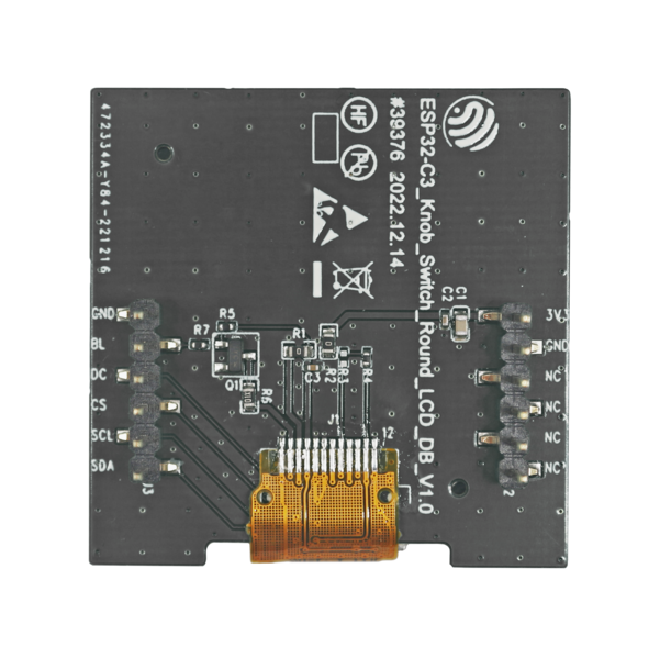
ESP32-C3-LCD-Ev-Board_DB - Back (Click to Enlarge)
Software Support
The ESP32-C3-LCD-Ev-Board development framework is ESP-IDF. ESP-IDF is a FreeRTOS-based SoC development framework with a bunch of components including LCD, ADC, RMT, and SPI.
Start Application Development
This section provides instructions on how to do hardware and software setup and flash firmware onto the board to develop your own application.
Required Hardware
1 x ESP32-C3-LCD-Ev-Board_MB
1 x LCD subboard
1 x USB 2.0 cable (standard Type-A to Type-C)
1 x PC (Windows, Linux, or macOS)
Note
Please make sure to use the appropriate USB cable. Some cables can only be used for charging, not for data transfer or program flashing.
Hardware Setup
Prepare the board for loading of the first sample application:
Connect the LCD subboard to the LCD Board Connector.
Plug in the USB cable to connect the PC with the board.
The LCD lights up and you can start to interact with it.
Now the board is ready for software setup.
Software Setup
To learn how to quickly set up your development environment, please go to Get Started > Installation.
For more software information on developing applications, please go to Software Support.
Hardware Reference
This section provides more detailed information about the board’s hardware.
GPIO Allocation
The table below provides the allocation of GPIOs exposed on terminals of ESP32-C3-MINI-1 module to control specific components or functions of the board.
Pin |
Pin Name |
Function |
|---|---|---|
1 |
GND |
Ground |
2 |
GND |
Ground |
3 |
3V3 |
Power supply |
4 |
NC |
No connection |
5 |
IO2 |
Reserved |
6 |
IO3 |
Reserved |
7 |
NC |
No connection |
8 |
EN |
Reset |
9 |
NC |
No connection |
10 |
NC |
No connection |
11 |
GND |
Ground |
12 |
IO0 |
LCD_SDA |
13 |
IO1 |
LCD_SCL |
14 |
GND |
Ground |
15 |
NC |
No connection |
16 |
IO10 |
LCD_CS |
17 |
NC |
No connection |
18 |
IO4 |
LCD_D/C |
19 |
IO5 |
LCD_BL_CTRL |
20 |
IO6 |
ENCODER_B |
21 |
IO7 |
ENCODER_A |
22 |
IO8 |
LED |
23 |
IO9 |
BOOT, ENCODER_SW |
24 |
NC |
No connection |
25 |
NC |
No connection |
26 |
IO18 |
Reserved |
27 |
IO19 |
Reserved |
28 |
NC |
No connection |
29 |
NC |
No connection |
30 |
RXD0 |
RXD0 |
31 |
TXD0 |
TXD0 |
32-35 |
NC |
No connection |
36-53 |
GND |
Ground |
Power Distribution
The development board is powered via the USB-to-USB port:
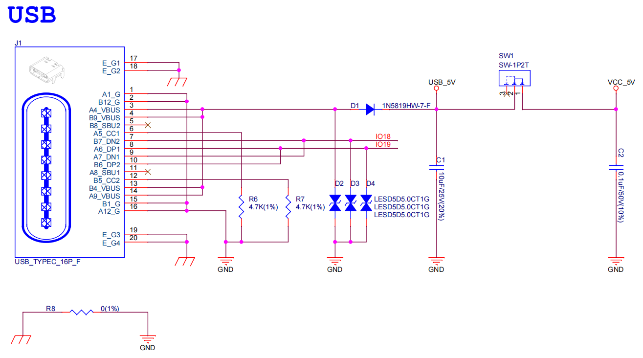
ESP32-C3-LCD-Ev-Board - USB-to-USB Power Supply
Output system power supply:
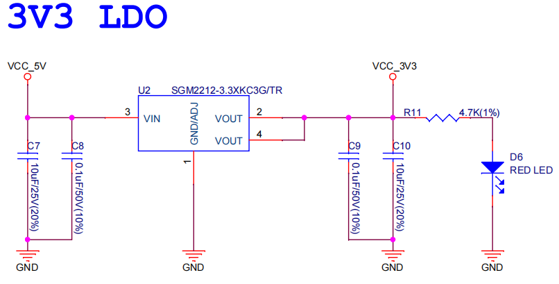
ESP32-C3-LCD-Ev-Board - System Power Supply
Hardware Setup Options
Automatic Download
There are two ways to put the development board into download mode.
Press the Boot and Reset buttons. Release the Reset button first and then the Boot button.
Controls the status of the EN and IO9 pins of the ESP development board by ESP-Prog.
Hardware Revision Details
No previous revisions.
Sample Request
Not available.