Detailed Explanation of LCD Screen Tearing
This section aims to introduce the principle of screen tearing on LCD displays and the corresponding solutions.
Terminology
Please refer to the LCD Terms Table 。
The principle of screen tearing
Phenomenon
Screen tearing, also known as tearing effect, is a common issue in LCD applications, typically occurring when there is a full-screen or large area change in the GUI. The phenomenon involves displaying different parts of several frames simultaneously on the LCD, causing noticeable visual discontinuities in the image, significantly degrading the visual experience of the GUI. Below are the visual effects of running the LVGL Music example with and without screen tearing.
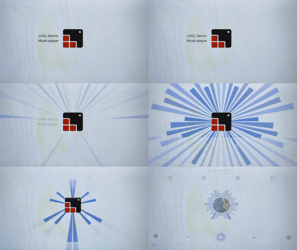
The visual effect of screen tearing occurring

The visual effect diagram without screen tearing
Reason
Next, a series of assumptions will be set and combined with schematic diagrams to detail the reasons for screen tearing. For convenience, the screen refresh process here is simplified into two steps: write and read. Writing refers to the process where the main controller writes the rendered color data into the frame buffer (GRAM), while reading refers to the continuous process where the screen reads color data from GRAM and displays it on the panel. Below is a simplified schematic diagram of the screen refresh process.

Simplified screen refresh schematic diagram
Note
Some LCDs can control the direction of main controller writing and screen reading through commands, such as the 36h command of ST7789. When the directions are inconsistent, screen tearing may also occur. Subsequently, explanations will only be provided for cases where the reading and writing directions are consistent.
When the main controller does not perform any synchronization operations during writing, meaning the initial position and time of writing are both unknown, screen tearing may occur if the speeds of writing and reading are not equal.
Assuming that the writing speed is slower than the reading speed (using a speed ratio of 1:2 as an example), during the process of the main controller writing the second frame of the image, the reading position will surpass the writing position. This results in the screen only reading the front half of the second frame of the image, leading to a torn display image. Below is a schematic diagram of the demonstration process.
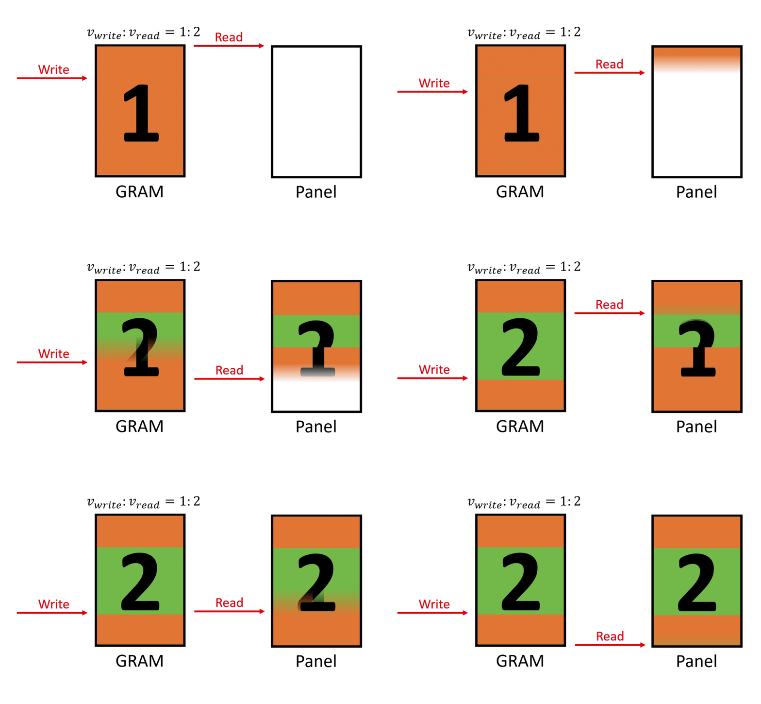
Schematic diagram of asynchronous writing and reading with a speed ratio of 1:2
Assuming that the writing speed is faster than the reading speed (using a speed ratio of 2:1 as an example), during the process of the screen reading the first frame of the image, the writing position will surpass the reading position. This results in the screen reading the back half of the second frame of the image, leading to a torn display image. Below is a schematic diagram of the demonstration process.
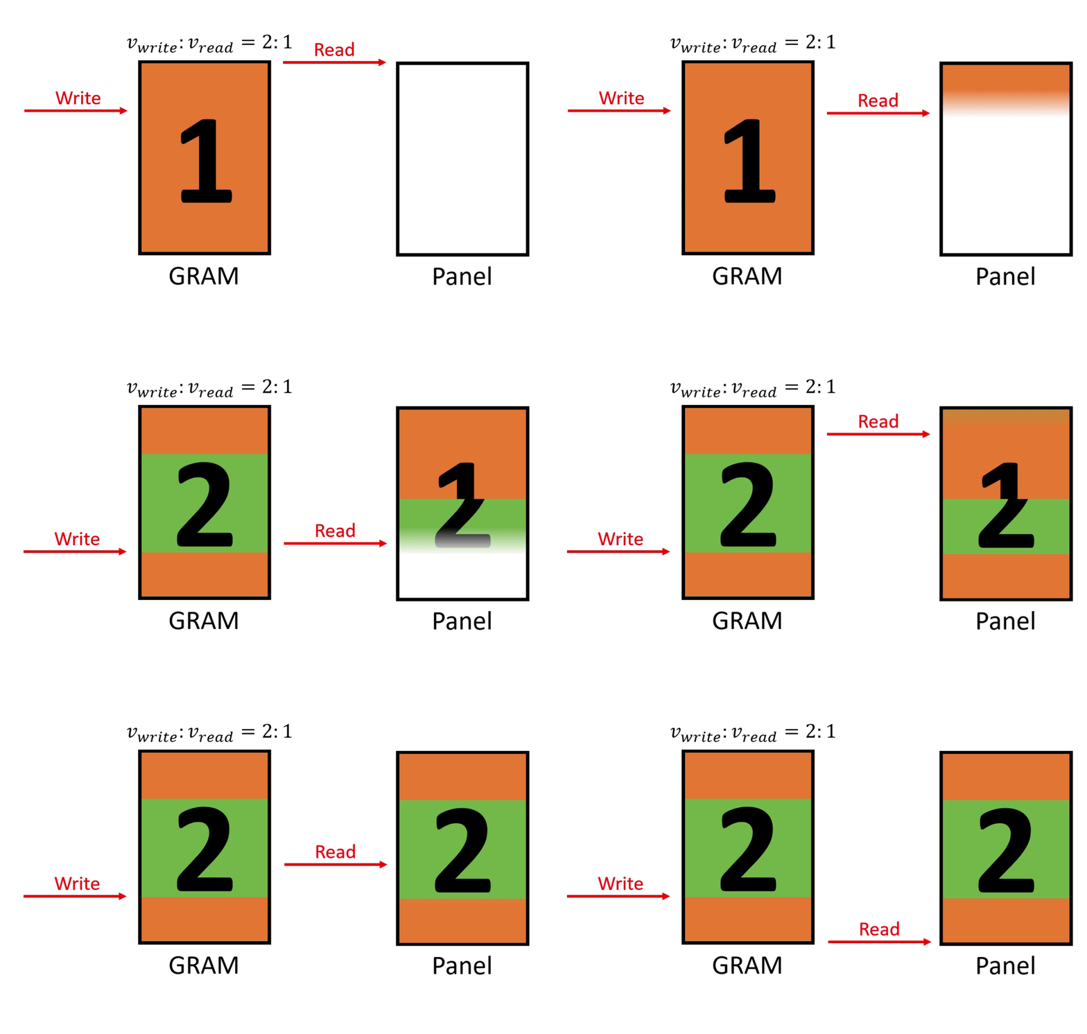
Schematic diagram of asynchronous writing and reading with a speed ratio of 2:1
When the main controller performs synchronization operations during writing, meaning the initial position and time of writing are synchronized with reading, screen tearing may still occur if the speeds of writing and reading do not match.
Assuming that the writing speed is less than half of the reading speed (using a speed ratio of 1:3 as an example), during the process of the main controller writing the second frame of the image, the reading position will surpass the writing position. This results in the screen only reading the front half of the second frame of the image, leading to a torn display image. Below is a schematic diagram of the demonstration process.
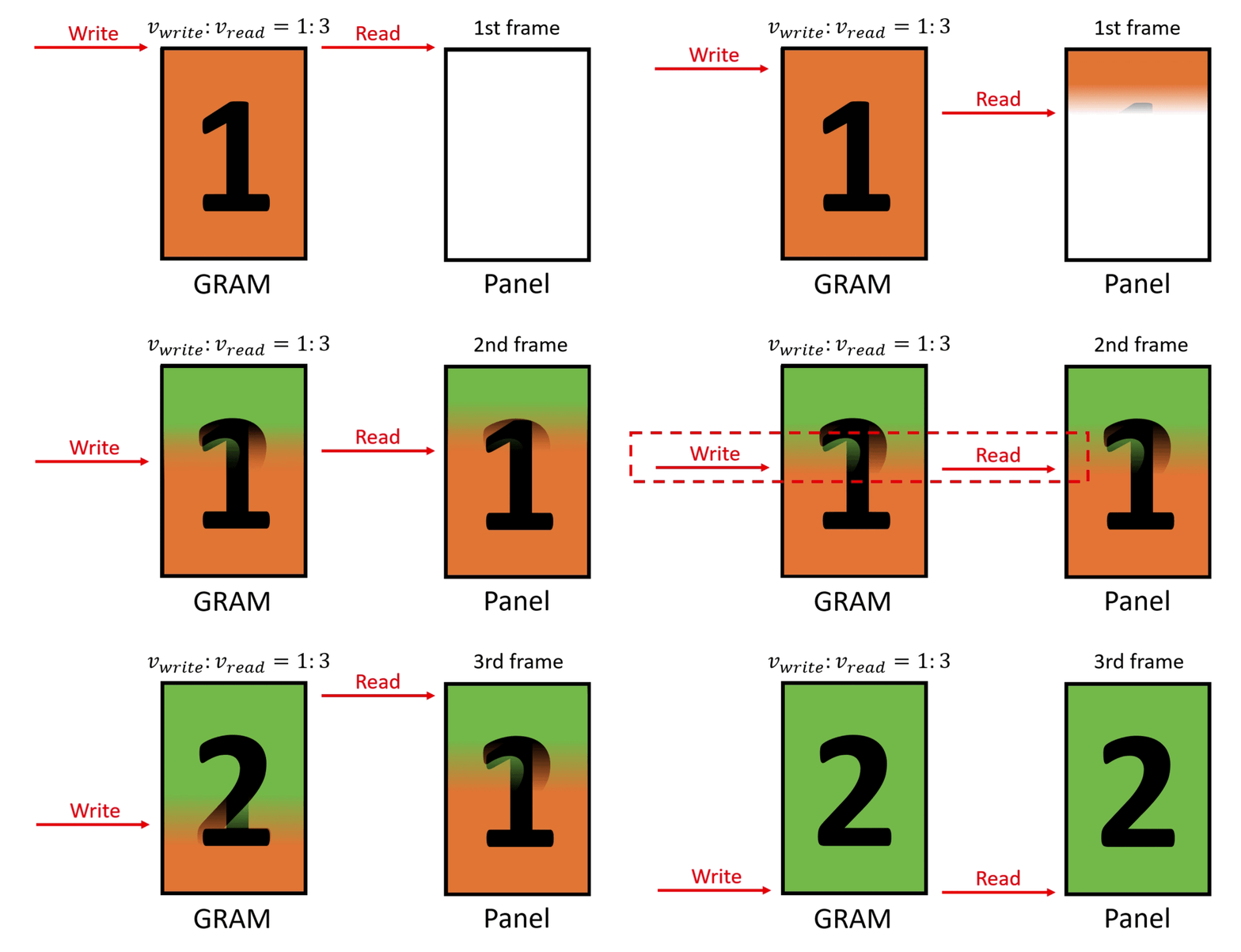
Schematic diagram of synchronous writing and reading with a speed ratio of 1:3
Assuming that the writing speed is greater than or equal to half of the reading speed (using a speed ratio of 1:2 as an example), during the process of the main controller writing the second frame of the image, the reading position will not overlap with the writing position. This allows the screen to read the complete second frame of the image, ensuring that the display image does not tear. Below is a schematic diagram of the demonstration process.
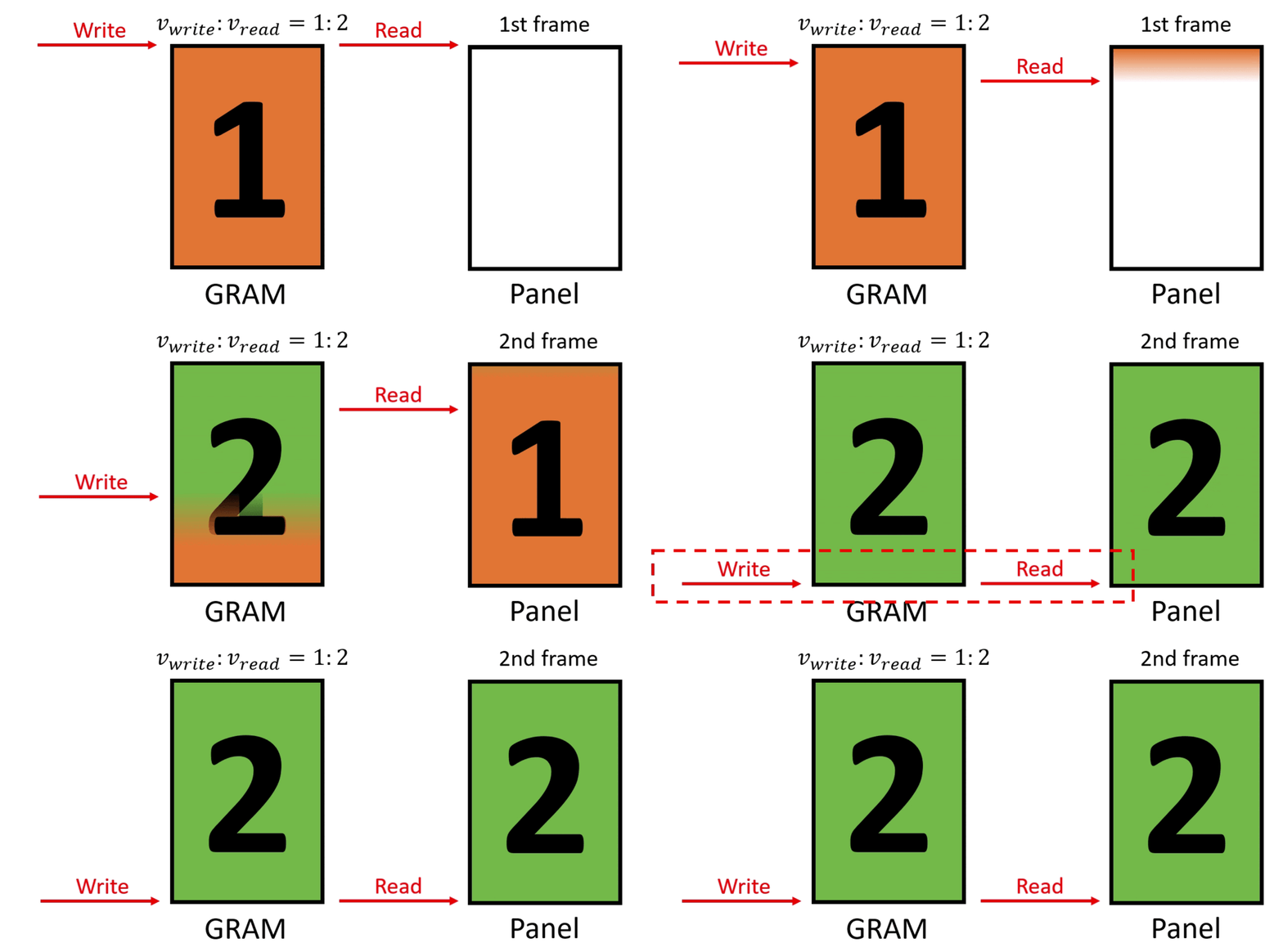
Schematic diagram of synchronous writing and reading with a speed ratio of 1:2
Based on the assumptions above, the main reasons for screen tearing include the following two points:
Simultaneous operation of writing and reading to the same GRAM
The initial states of writing and reading are not synchronized or their speeds do not match
Methods to prevent screen tearing
After understanding the causes of screen tearing, methods to prevent tearing can be implemented from two perspectives: GRAM and the synchronization of reading and writing states and speeds. Due to the different refresh mechanisms and GRAM positions of LCDs with different interface types, it is necessary to select the recommended anti-tearing methods based on the specific interface type. The table below shows the positions of GRAM and the corresponding anti-tearing methods for different interface types.
Interface types |
GRAM position |
Anti-tearing methods |
|---|---|---|
RGB, MIPI-DSI (video mode), QSPI (without internal GRAM) |
main controller |
|
SPI, I80, QSPI (with internal GRAM) |
LCD |
The method based on multiple GRAM
This method is suitable for the situation where GRAM is in the main controller, and requires the main controller to be able to freely adjust the target GRAM for screen reading. The working principle is: by adding additional GRAM to avoid writing and reading operating on the same GRAM simultaneously. The following introduces the anti-tearing method based on dual GRAM, and the schematic diagram of the demonstration process is as follows.
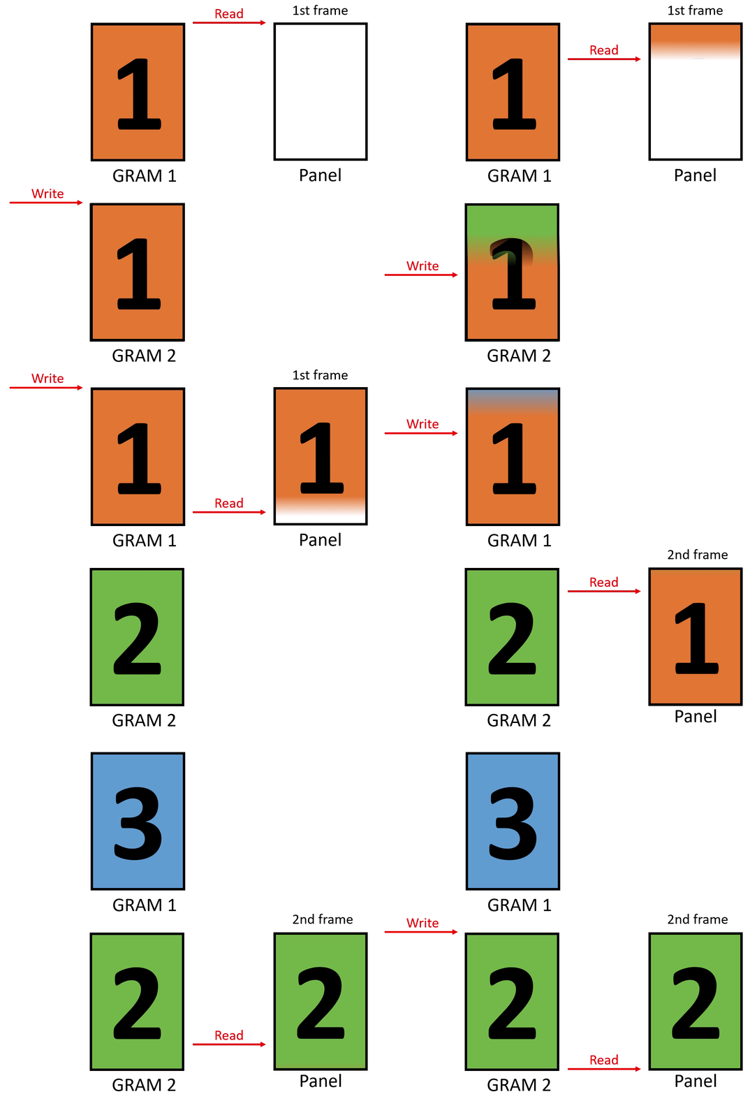
Schematic diagram of anti-tearing implemented based on dual GRAM
From the diagram, it can be seen that initially the main controller is ready to write the second frame image into GRAM2, while the screen is ready to read the first frame image from GRAM1. After the main controller completes the writing, it first needs to set the screen to read from GRAM2 for the next frame, and then wait for the screen to finish reading the current frame image. After the screen finishes reading, it then starts reading the second frame image from GRAM2, while the main controller also starts writing the third frame image into GRAM1. Therefore, writing and reading will not operate on the same GRAM simultaneously, thus avoiding screen tearing.
Here is the relevant sample code implemented based on LVGL:
Note
To optimize display performance, an additional GRAM can be added on top of using two GRAMs. In this case, after the main controller completes writing one frame, it does not need to wait for the screen to finish reading one frame, but can directly start writing the next frame. For how to implement the anti-tearing method with three GRAMs, please refer to the sample code.
The method based on the TE signal
This method is suitable for the situation where GRAM is inside the LCD, and requires the LCD to provide an external TE signal pin. The working principle is: controlling the initial state of writing through the TE signal to keep it synchronized with reading, while ensuring that the writing speed is not less than half of the reading speed, thereby avoiding overlap between writing and reading at the middle position of the GRAM. The following introduces the anti-tearing method based on the TE signal, and the schematic diagram of the demonstration process is as follows.
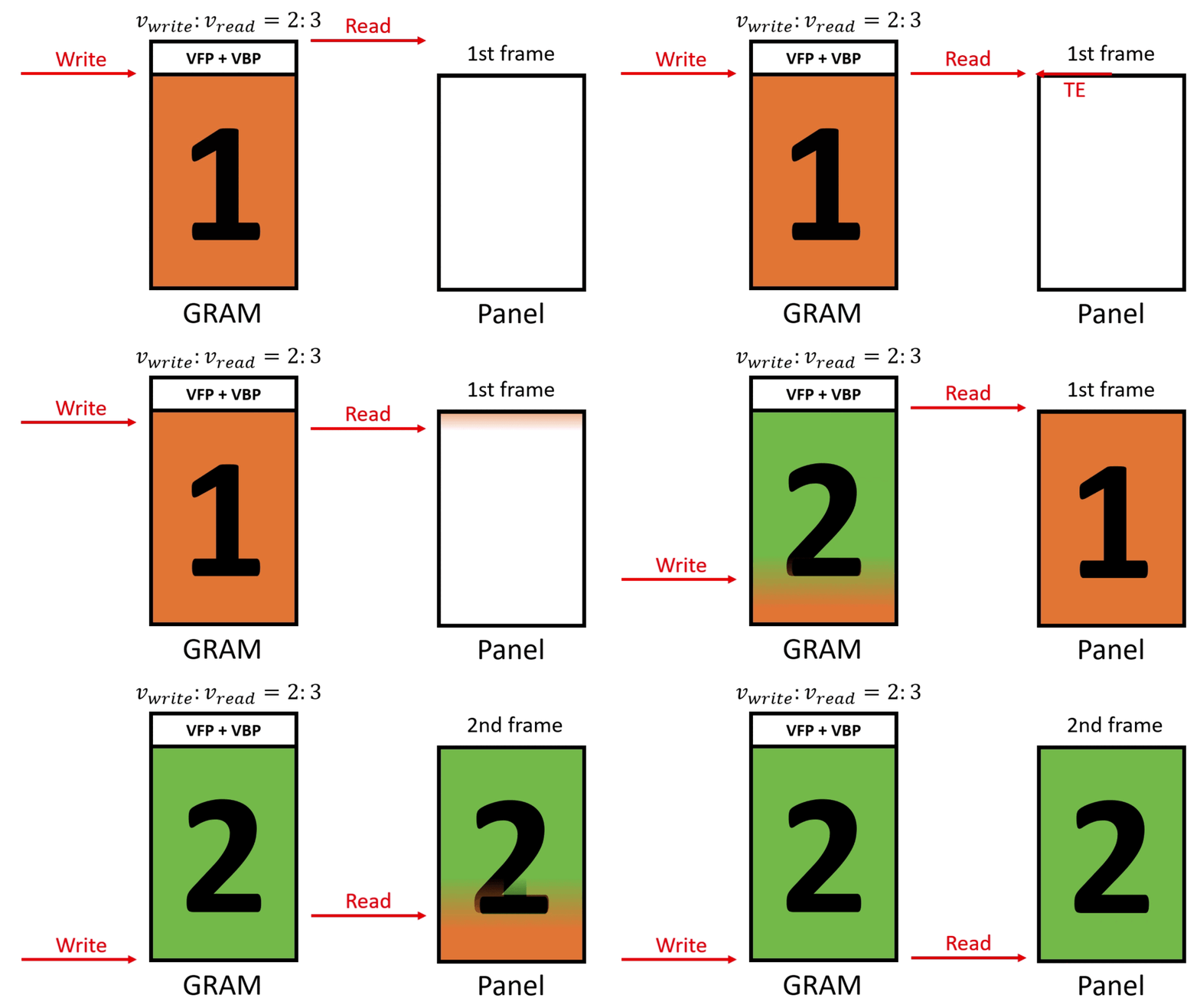
Schematic diagram of anti-tearing implemented based on the TE signal
From the diagram, it can be seen that initially the main controller is waiting for the TE signal, while the screen is preparing to enter the blanking area (Porch). When the screen starts reading the first frame image from the GRAM, it sends the TE signal to the main controller. Upon receiving the TE signal, the main controller starts writing the second frame image to the GRAM, ensuring that the ratio of writing speed to reading speed is 2:3. Therefore, writing and reading will not overlap at the middle position of the GRAM, thus avoiding screen tearing.
Here is the relevant sample code implemented based on LVGL:
Note
Some LCDs can control the switch of the TE signal and trigger timing parameters through commands, such as the
35hand44hcommands of ST7789. To ensure the effectiveness of the above method, users need to set the corresponding parameters according to the data sheet of the specific LCD driver IC, so that the TE signal is enabled and triggered at the appropriate position.Some LCDs can control the direction of writing by the main controller and reading by the screen through commands, such as the
36hcommand of ST7789. When the directions are inconsistent, the above method to prevent screen tearing will be ineffective. Users need to set the corresponding parameters according to the data sheet of the specific LCD driver IC to ensure that the direction of writing and reading is consistent.