Overview of Bldc Motor Control
This guide includes the following content:
Overview of Bldc Motor: Advantages of bldc motor
Drive Method: Drive hardware methods
Control Method: Various ways to control bldc motor
Overview of Bldc Motor
Brushless Direct Current (BLDC) motor is a type of synchronous motor and can be configured as single-phase, two-phase, or three-phase. This article discusses three-phase bldc motor.
BLDC motor do not use brushes for commutation but instead use electronic commutation, offering the following advantages:
Better speed-torque characteristics
Fast dynamic response
High efficiency
Long lifespan
No operational noise
Wide speed range
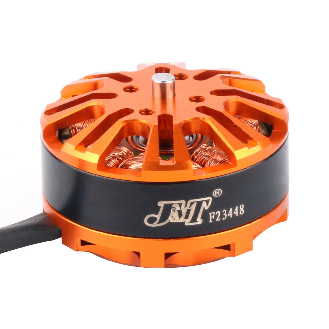
BLDC Brushless Motor
BLDC motor consists of two parts: the stator and the rotor:
The stator is the armature with coil windings and has three star-connected stator windings distributed along the stator circumference to form evenly distributed magnetic poles.
The rotor is made of permanent magnets, typically with 2 to 8 magnetic poles, alternating between north and south poles.

BLDC Brushless Motor Operation
If a fixed DC current is applied to the motor, it will only generate a constant magnetic field and cannot rotate. By appropriately sequencing the stator phase energization, a rotating magnetic field is produced. The rotor’s inherent magnetic poles follow the rotating magnetic field of the stator in an orderly manner, achieving rotation.
Note
Ideally, the torque peak occurs when the two magnetic fields are perpendicular, and is weakest when they are parallel.
Important Parameters:
KV value (rpm/V): Indicates the specific speed of the bldc motor at a specific operating voltage.
Torque (Nm): The driving torque generated by the rotor to drive mechanical loads.
Speed (rpm): The motor’s rotational speed per minute.
Maximum current (A): The maximum current that can be safely sustained.
Pole pairs Pp: The number of magnets on the rotor divided by 2. This can be determined by manually rotating the motor one full turn with a small voltage applied to any two phases and counting the number of resistances felt. If 6 resistances are felt, the pole pair number is 6.
Phase inductance LS (H): The inductance across the stator windings when the motor is stationary, with the phase inductance being half of it:
Phase resistance RS (Ω): The resistance between two phases measured with a multimeter, with the phase resistance being half of it:
Drive Method
BLDC motors are generally driven by an inverter circuit composed of 6 MOSFETs. By appropriately switching the upper and lower arm devices, a rotating magnetic field is produced on the stator.

BLDC Three-phase Inverter Circuit
Through the inverter circuit shown in the figure, the rotor magnet can rotate in cycles by sequentially switching the current. The rotor completes one full rotation every 6 current switches. This demonstrates the method of conducting two bridge arms.
Note
The upper and lower bridge arms cannot be turned on simultaneously; otherwise, a short circuit will occur. Therefore, dead time control must be introduced to prevent the upper and lower bridge arms of the same phase from being turned on simultaneously.
Upper Arm Conduction |
Lower Arm Conduction |
Phase Current A |
Phase Current B |
Phase Current C |
|---|---|---|---|---|
UH |
WL |
DC+ |
Floating |
DC- |
UH |
VL |
DC+ |
DC- |
Floating |
WH |
VL |
Floating |
DC- |
DC+ |
WH |
UL |
DC- |
Floating |
DC+ |
VH |
UL |
DC- |
DC+ |
Floating |
VH |
WL |
Floating |
DC+ |
DC- |
To make the motor’s rotational speed controllable, the control signal applied to the upper arm can be set as a PWM signal, and by adjusting the PWM duty cycle, the rotational speed can be controlled.

BLDC PWM Speed Control
Control Method
In actual motor control, it is necessary to obtain the rotor position and calculate the next bridge arm to be turned on in order to make the motor rotate. There are generally two methods to obtain the rotor position: sensor-based detection and sensorless detection.
Sensor-based Hall Effect
In bldc motor, three switch-type Hall effect sensors are typically used to detect the rotor’s position, installed 120° apart, as shown below.
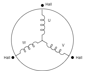
BLDC Hall Sensor Installation
When the N pole approaches Hall sensor a, a outputs a high level (1), and when the N pole moves away from a, a outputs a low level. The same applies to the other sensors. When the rotor completes one full rotation, it produces the following waveform.

BLDC Hall Sensor Waveform
By interpreting the output of the Hall sensors, the current position of the rotor is determined. The “two-two conduction” method is used to make the motor rotate, but it has the following drawbacks:
The sensors are expensive and need to be installed on the motor during manufacturing, increasing installation and wiring costs.
If the sensors fail, the motor cannot continue to operate.
Using sensors that do not meet practical needs may result in sensor failure.
Therefore, sensorless control schemes for bldc motor have become mainstream.
Sensorless Detection
In some micro-motor systems, installing position sensors negatively affects the motor’s size and cost. Therefore, sensorless position detection is crucial. Sensorless control strategies mainly include the back-EMF method, inductance method, and freewheeling diode method. Among them, the back-EMF method is one of the most widely used and mature schemes.
Back-EMF
Back-EMF, according to Lenz’s Law, is opposite in direction to the main voltage provided to the windings. The polarity of back-EMF is opposite to the excitation voltage. Back-EMF mainly depends on three factors:
Rotor angular speed
Magnetic field produced by the rotor magnets
Number of turns in the stator winding
For motors, the rotor magnetic field and the number of turns in the stator winding are fixed, so in actual operation, the only factor determining back-EMF is angular speed, or rotor speed. During each commutation, one winding receives positive voltage, the second receives negative voltage, and the third remains open-circuited.
By detecting the zero-crossing points of the back-EMF in each phase winding, the rotor’s six positions can be obtained within one electrical cycle. The zero-crossing point of the back-EMF in the non-conducting phase delayed by 30° electrical angle is the commutation point.
Note
When the motor speed is extremely slow, the amplitude of the back-EMF is very low, making it difficult to detect the zero-crossing point.
There are two ways to detect the zero-crossing point based on back-EMF:
Sensorless Square Wave Motor Control Based on ADC Sampling ADC Sampling Zero-crossing Detection
Sensorless Square Wave Motor Control Based on Comparator Detection Comparator Zero-crossing Detection
In addition, there is a sensorless FOC scheme based on phase current acquisition:
Dual-resistor Sensorless FOC Scheme (to be updated)