Serial Protocol
This is technical documentation for the serial protocol used by the UART bootloader in the ESP32-C3 ROM and the esptool stub loader program.
The UART bootloader runs on chip reset if certain strapping pins are set. See Entering the Bootloader for details of this process.
By default, esptool uploads a stub “software loader” to the IRAM of the chip. The stub loader then replaces the ROM loader for all future interactions. This standardizes much of the behavior. Pass --no-stub to esptool in order to disable the stub loader. See Flasher Stub for more information.
Note
There are differences in the serial protocol between ESP chips! To switch to documentation for a different chip, choose the desired target from the dropdown menu in the upper left corner.
Packet Description
The host computer sends a SLIP encoded command request to the ESP chip. The ESP chip responds to the request with a SLIP encoded response packet, including status information and any data as a payload.
Low Level Protocol
The bootloader protocol uses SLIP packet framing for data transmissions in both directions.
Each SLIP packet begins and ends with 0xC0. Within the packet, all occurrences of 0xC0 and 0xDB are replaced with 0xDB 0xDC and 0xDB 0xDD, respectively. The replacing is to be done after the checksum and lengths are calculated, so the packet length may be longer than the size field below.
Command Packet
Each command is a SLIP packet initiated by the host and results in a response packet. Inside the packet, the packet consists of a header and a variable-length body. All multi-byte fields are little-endian.
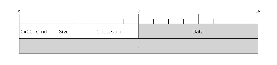
Command packet format
Byte |
Name |
Comment |
|---|---|---|
0 |
Direction |
Always |
1 |
Command |
Command identifier (see Commands). |
2-3 |
Size |
Length of Data field, in bytes. |
4-7 |
Checksum |
Simple checksum of part of the data field (only used for some commands, see Checksum). |
8..n |
Data |
Variable length data payload (0-65535 bytes, as indicated by Size parameter). Usage depends on specific command. |
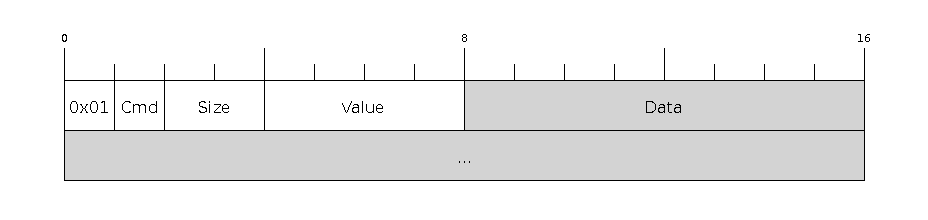
Response Packet
Each received command will result in a response SLIP packet sent from the ESP chip to the host. Contents of the response packet is:
Command packet format
Byte |
Name |
Comment |
|---|---|---|
0 |
Direction |
Always |
1 |
Command |
Same value as Command identifier in the request packet that triggered the response |
2-3 |
Size |
Size of data field. At least the length of the Status Bytes (2 or 4 bytes, see below). |
4-7 |
Value |
Response value used by READ_REG command (see below). Zero otherwise. |
8..n |
Data |
Variable length data payload. Length indicated by “Size” field. |
Status Bytes
The final bytes of the Data payload indicate command status:
For stub loader the final two bytes indicate status (most commands return at least a two byte Data payload):
Byte |
Name |
Comment |
|---|---|---|
Size-2 |
Status |
Status flag, success ( |
Size-1 |
Error |
If Status is 1, this indicates the type of error. |
For ESP32-C3 ROM (only, not the stub loader) the final four bytes are used, but only the first two bytes contain status information:
Byte |
Name |
Comment |
|---|---|---|
Size-4 |
Status |
Status flag, success ( |
Size-3 |
Error |
If Status 1, this indicates the type of error. |
Size-2 |
Reserved |
|
Size-1 |
Reserved |
ROM Loader Errors
The ROM loader sends the following error values
Value |
Meaning |
|---|---|
|
“Undefined errors” |
|
“The input parameter is invalid” |
|
“Failed to malloc memory from system” |
|
“Failed to send out message” |
|
“Failed to receive message” |
|
“The format of the received message is invalid” |
|
“Message is ok, but the running result is wrong” |
|
“Checksum error” |
|
“Flash write error” - after writing a block of data to flash, the ROM loader reads the value back and the 8-bit CRC is compared to the data read from flash. If they don’t match, this error is returned. |
|
“Flash read error” - SPI read failed |
|
“Flash read length error” - SPI read request length is wrong |
|
“Deflate failed error” (compressed uploads only) |
|
“Deflate Adler32 error” |
|
“Deflate parameter error” |
|
“Invalid RAM binary size” |
|
“Invalid RAM binary address” |
|
“Invalid parameter” |
|
“Invalid format” |
|
“Description too long” |
|
“Bad encoding description” |
|
“Insufficient storage” |
Stub Loader Status & Error
If the stub loader is used:
The status response is always 2 bytes regardless of chip type.
Stub loader error codes are entirely different to the ROM loader codes. They all take the form
0xC*, or0xFFfor “unimplemented command”. (Full list here).
After sending a command, the host should continue to read response packets until one is received where the Command field matches the request’s Command field, or a timeout is exceeded.
Commands
Supported by Stub Loader and ROM Loader
Byte |
Name |
Description |
Input Data |
Output Data |
|---|---|---|---|---|
|
FLASH_BEGIN |
Four 32-bit words: size to erase, number of data packets, data size in one packet, flash offset. A fifth 32-bit word passed to ROM loader only: |
||
|
FLASH_DATA |
Four 32-bit words: data size, sequence number, |
||
|
FLASH_END |
One 32-bit word: |
||
|
MEM_BEGIN |
Total size, number of data packets, data size in one packet, memory offset |
||
|
MEM_END |
Two 32-bit words: execute flag, entry point address |
||
|
MEM_DATA |
Four 32-bit words: data size, sequence number, |
||
|
SYNC |
36 bytes: |
||
|
WRITE_REG |
Four 32-bit words: address, value, mask and delay (in microseconds) |
||
|
READ_REG |
Address as 32-bit word |
Read data as 32-bit word in |
|
|
SPI_SET_PARAMS |
Six 32-bit words: id, total size in bytes, block size, sector size, page size, status mask. |
||
|
SPI_ATTACH |
32-bit word: Zero for normal SPI flash. A second 32-bit word (should be |
||
|
CHANGE_BAUDRATE |
Two 32-bit words: new baud rate, |
||
|
FLASH_DEFL_BEGIN |
Four 32-bit words: uncompressed size, number of data packets, data packet size, flash offset. With stub loader the uncompressed size is exact byte count to be written, whereas on ROM bootloader it is rounded up to flash erase block size.
A fifth 32-bit word passed to ROM loader only: |
||
|
FLASH_DEFL_DATA |
Four 32-bit words: data size, sequence number, |
Error code |
|
|
FLASH_DEFL_END |
One 32-bit word: |
||
|
SPI_FLASH_MD5 |
Four 32-bit words: address, size, |
Body contains 16 raw bytes of MD5 followed by 2 status bytes (stub loader) or 32 hex-coded ASCII (ROM loader) of calculated MD5 |
|
|
GET_SECURITY_INFO |
Read chip security info |
32 bits |
Supported by Stub Loader Only
ROM loaders will not recognize these commands.
Byte |
Name |
Description |
Input |
Output |
|---|---|---|---|---|
|
ERASE_FLASH |
Erase entire flash chip |
||
|
ERASE_REGION |
Erase flash region |
Two 32-bit words: flash offset to erase, erase size in bytes. Both must be multiples of flash sector size. |
|
|
READ_FLASH |
Four 32-bit words: flash offset, read length, flash sector size, read packet size, maximum number of un-acked packets |
||
|
RUN_USER_CODE |
Exits loader and runs user code |
Supported in Secure Download Mode
Secure Download Mode is a restricted version of the ROM Loader available on Espressif chips. It only allows a limited set of commands:
synchronisation (
SYNC)attaching SPI flash (
SPI_ATTACH)updating SPI config (
SPI_SET_PARAMS)changing baud rate (
CHANGE_BAUDRATE)basic flash write (
FLASH_BEGIN,FLASH_DATA,FLASH_END)reading a summary of currently enabled security features (
GET_SECURITY_INFO)
Any other command (e.g., reading or writing memory, arbitrary code execution through loading to RAM, …) will result in an error.
You can read more about Secure Download Mode in the ESP-IDF Security Overview or read about its limitations here.
Checksum
The checksum field is ignored (can be zero) for all commands except for MEM_DATA, FLASH_DATA, and FLASH_DEFL_DATA.
Each of the _DATA command packets (like FLASH_DEFL_DATA, MEM_DATA) has the same “data payload” format:
Bytes |
Name |
Format |
|---|---|---|
0-3 |
“Data to write” length |
Little endian 32-bit word. |
4-7 |
Sequence number |
Little endian 32-bit word. The sequence numbers are 0 based. |
8-15 |
0 |
Two words of all zeroes, unused. |
16- |
“Data to write” |
Length given at beginning of payload. |
The checksum is only applied to this final “data to write” section, not the first 16 bytes of data.
To calculate checksum, start with seed value 0xEF and XOR each individual byte in the “data to write”. The 8-bit result is stored in the checksum field of the packet header (as a little endian 32-bit value).
Note
Because this checksum is not adequate to ensure valid data, the SPI_FLASH_MD5 command was added to validate flash contents after flashing. It is recommended that this command is always used. See Verifying Uploaded Data, below.
Functional Description
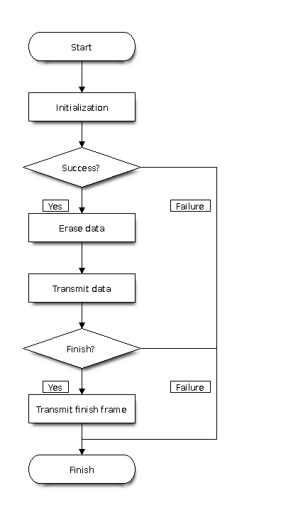
Download procedure flow chart
Note
This flow chart is used to illustrate the download procedure (writing to flash), other commands have different flows.
Initialization
The ESP chip is reset into UART bootloader mode. The host starts by sending SYNC commands. These commands have a large data payload which is also used by the ESP chip to detect the configured baud rate. ESP32-C3 always initialises at 115200bps. However the sync packets can be sent at any baud rate, and the UART peripheral will detect this.
The host should wait until it sees a valid response to a SYNC command, indicating the ESP chip is correctly communicating.
Chip type detection then uses various methods to identify chip type, subtype, revision, etc. See below.
Esptool then (by default) uses the “RAM Download” sequence to upload stub loader code to IRAM of the chip. The MEM_END command contains the entry-point address to run the stub loader. The stub loader then sends a custom SLIP packet of the sequence OHAI (
0xC0 0x4F 0x48 0x41 0x49 0xC0), indicating that it is now running. This is the only unsolicited packet ever sent by the ESP. If the--no-stubargument is supplied to esptool, this entire step is skipped.For commands which need to use the flash, the ESP32-C3 ROM an stub loader requires the SPI_ATTACH and SPI_SET_PARAMS commands. See SPI Configuration Commands.
For stub loader and/or ESP32-C3 ROM loader, the host can send a CHANGE_BAUD command to set the baud rate to an explicit value. Compared to auto-detecting during the SYNC pulse, this can be more reliable for setting very high baud rate. Esptool tries to sync at (maximum) 115200bps and then sends this command to go to a higher baud rate, if requested.
Initialization - Chip Type Detection
ESP32-C3 Chip Detection
ESP32-C3 is detected by using GET_SECURITY_INFO (0x14) command and its chip-id value.
Overview of Detection for All Chips
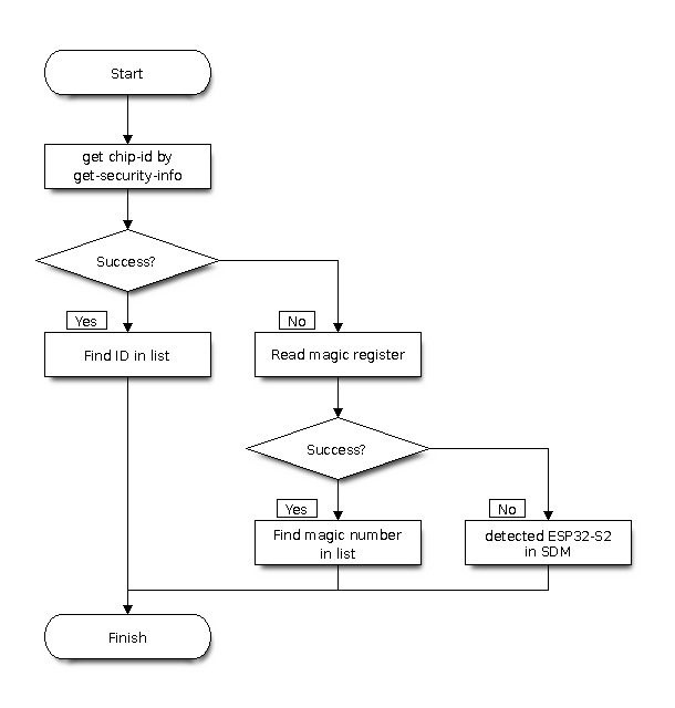
All chips detection flow chart
On older devices that do not support the GET_SECURITY_INFO (0x14) command (which provides the chip-id), esptool falls back to reading a magic register to determine the chip type.
The main exception is the ESP32-S2: although it supports the GET_SECURITY_INFO (0x14) command, the output lacks the chip-id. Therefore, esptool uses the magic register as a fallback for this chip as well. If reading the register also fails, it indicates the chip is in secure download mode.
For details see: esptool chip detection code
Writing Data
(Includes RAM Download, Flash Download, Compressed Flash Download.)
RAM Download (MEM_BEGIN, MEM_DATA, MEM_END) loads data into the ESP chip memory space and (optionally) executes it.
Flash Download (FLASH_BEGIN, FLASH_DATA) flashes data into the ESP SPI flash.
Compressed Flash Download is the same, only the data is compressed using the gzip Deflate algorithm to reduce serial overhead.
All three of these sequences follow a similar pattern:
A _BEGIN command (FLASH_BEGIN, etc) is sent which contains basic parameters for the flash erase size, start address to write to, etc. The uploader also needs to specify how many “blocks” of data (ie individual data packets) will be sent, and how big each packet is.
One or more _DATA commands (FLASH_DATA, etc) is sent where the data payload contains the actual data to write to flash/RAM. In the case of Compressed Flash Downloads, the data is compressed using the gzip deflate algorithm. The number of _DATA commands is specified in the _BEGIN command, as is the size of each _DATA payload. The last data block should be padded to the block size with 0xFF bytes.
An _END command (FLASH_END, etc) is sent to exit the bootloader and optionally reset the chip (or jump to an address in RAM, in the case of MEM_END). Not necessary to send after flashing if you wish to continue sending other or different commands.
It’s not necessary to send flash erase commands before sending commands to write to flash, etc. The ROM loaders erase the to-be-written region in response to the FLASH_BEGIN command. The stub loader does just-in-time erasing as it writes data, to maximize overall flashing performance (each block of data is read into RAM via serial while the previous block is simultaneously being written to flash, and 4KB and 64KB erases are done as needed before writing to flash).
The block size chosen should be small enough to fit into RAM of the device. Esptool uses 16KB which gives good performance when used with the stub loader.
Verifying Uploaded Data
The 8-bit checksum used in the upload protocol is not sufficient to ensure valid flash contents after upload. The uploader should send the SPI_FLASH_MD5 command or use another method to verify flash contents.
The SPI_FLASH_MD5 command passes the start address in flash and the size of data to calculate. The MD5 value is returned in the response payload, before the status bytes.
Note that the ESP32-C3 ROM loader returns the md5sum as 32 hex encoded ASCII bytes, whereas the stub loader returns the md5sum as 16 raw data bytes of MD5 followed by 2 status bytes.
SPI Configuration Commands
SPI Attach Command
The SPI_ATTACH command enables the SPI flash interface. It takes a 32-bit data payload which is used to determine which SPI peripheral and pins should be used to connect to SPI flash.
On the ESP32-C3 stub loader sending this command before interacting with SPI flash is optional. On ESP32-C3 ROM loader, it is required to send this command before interacting with SPI flash.
Value |
Meaning |
|---|---|
0 |
Default SPI flash interface |
1 |
HSPI interface |
(other values) |
Pin numbers as 6-bit values, packed into a 30-bit value. Order (from MSB): HD pin, Q pin, D pin, CS pin, CLK pin. |
The “Default SPI flash interface” uses pins configured via the SPI_PAD_CONFIG_xxx eFuses (if unset, these eFuses are all zero and the default SPI flash pins given in the datasheet are used.)
When writing the values of each pin as 6-bit numbers packed into the data word, each 6-bit value uses the following representation:
On ESP32-C3 ROM loader only, there is an additional 4 bytes in the data payload of this command. These bytes should all be set to zero.
SPI Set Parameters
The SPI_SET_PARAMS command sets some parameters of the attached SPI flash chip (sizes, etc).
All the values which are passed except total size are hardcoded, and most are not used when writing to flash. See flash_set_parameters function in esptool for the values which it sends.
32-Bit Read/Write
The 32-bit read/write commands (READ_REG, WRITE_REG) allow word-oriented reading and writing of memory and register data.
These commands can be used to manipulate peripherals in arbitrary ways. For example, the esptool “flash id” functionality is implemented by manipulating the SPI peripheral registers to send a JEDEC flash ID command to the flash chip and read the response.
Reading Flash
The stub loader implements a READ_FLASH command. This command behaves differently to other commands, including the ROM loader’s READ_FLASH command:
The host sends the READ_FLASH command and the data payload contains the offset, read size, size of each individual packet of data, and the maximum number of “un-acknowledged” data packets which can be in flight at one time.
The stub loader will send a standard response packet, with no additional data payload.
Now the stub loader will start sending SLIP packets with raw data (of the size requested in the command). There is no metadata included with these SLIP packets.
After each SLIP packet is received, the host should send back a 4 byte raw SLIP acknowledgement packet with the total number of bytes which have been received. There is no header or other metadata included with these SLIP packets.
The stub loader may send up to a maximum number (specified by the host in the READ_FLASH commands) of data packets before waiting for the first acknowledgement packet. No more than this “max in flight” limit can be un-acknowledged at any one time.
After all data packets are acknowledged received, the stub loader sends a 16 byte MD5 digest of all the data which was read from flash. This is also sent as a raw SLIP packet, with no metadata.
After the read flash process is complete, the stub loader goes back to normal command/response operation.
The ROM loader read flash command is more normal but also much slower to read data.
Tracing Esptool Serial Communications
esptool has a --trace option which can be supplied in the first group of arguments (before the command). This will dump all traffic sent and received via the serial port to the console.
Here is a sample extract, showing a READ_REG command and response:
TRACE +0.000   --- Cmd READ_REG (0x0a) | data_len 4 | wait_response 1 | timeout 3.000 | data 00100040 ---
TRACE +0.000   Write 14 bytes:       c0000a04000000000000100040c0
TRACE +0.046   Read 1 bytes:         c0
TRACE +0.000   Read 11 bytes:        010a0200090000000000c0
TRACE +0.000   Received full packet: 010a0200090000000000
The +X.XXX value is the time delta (in seconds) since the last trace line.
Values are printed in hexadecimal. If more than 16 bytes is printed at one time, a split display is used with hexadecimal bytes on the left and ASCII on the right. Non-printable characters are represented as . in ASCII:
Note that multiple protocol layers are represented in the logs. The “Write X bytes” lines show exactly which bytes are being sent “over the wire”, including SLIP framing. Similarly the “Read X bytes” lines show what bytes are being read over the wire, including any SLIP framing. Once a full SLIP packet is read, the same bytes - as a SLIP payload with any escaping removed - appear in the “Received full packet” log lines.
Here is a second example showing part of the initial synchronization sequence (lots of 0x55 bytes which are U in ASCII):
TRACE +0.000   Write 46 bytes:
  c000082400000000 0007071220555555 | ...$........ UUU
  5555555555555555 5555555555555555 | UUUUUUUUUUUUUUUU
  5555555555555555 5555555555c0     | UUUUUUUUUUUUU.
TRACE +0.012   Read 1 bytes:         c0
TRACE +0.000   Read 63 bytes:
  0108040007071220 00000000c0c00108 | ....... ........
  0400070712200000 0000c0c001080400 | ..... ..........
  0707122000000000 c0c0010804000707 | ... ............
  122000000000c0c0 01080400070712   | . .............
TRACE +0.000   Received full packet: 010804000707122000000000
TRACE +0.000   Received full packet: 010804000707122000000000
Important
If you don’t plan to use the esptool stub loader, pass --no-stub --trace to see interactions with the chip’s built-in ROM loader only. Otherwise, the trace will show the full binary upload of the loader.
In addition to this trace feature, most operating systems have “system call trace” or “port trace” features which can be used to dump serial interactions.