Firmware Image Format
This is technical documentation for the firmware image format used by the ROM bootloader. These are the images created by esptool elf2image.
Firmware image format
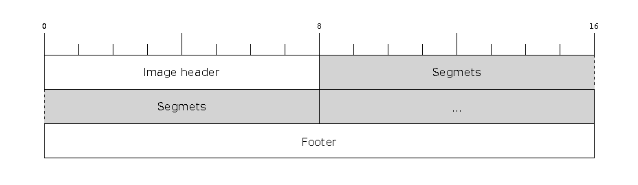
The firmware file consists of a header, a variable number of data segments and a footer. Multi-byte fields are little-endian.
File Header
Firmware image header
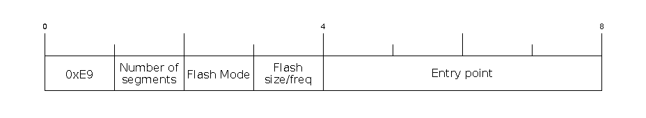
The image header is 8 bytes long:
Byte |
Description |
|---|---|
0 |
Magic number (always |
1 |
Number of segments |
2 |
SPI Flash Mode ( |
3 |
High four bits - Flash size ( Low four bits - Flash frequency ( |
4-7 |
Entry point address |
esptool overrides the 2nd and 3rd (counted from 0) bytes according to the SPI flash info provided through the command line options (see Flash Modes).
These bytes are only overridden if this is a bootloader image (an image written to a correct bootloader offset of 0x0).
In this case, the appended SHA256 digest, which is a cryptographic hash used to verify the integrity of the image, is also updated to reflect the header changes.
Generating images without SHA256 digest can be achieved by running esptool elf2image with the --dont-append-digest argument.
Individual segments come right after this header.
Segment
Byte |
Description |
|---|---|
0-3 |
Memory offset |
4-7 |
Segment size |
8…n |
Data |
Analyzing a Binary Image
To analyze a binary image and get a complete summary of its headers and segments, use the image-info command.