ESP32-C3-DevKitM-1
The ESP32-C3-DevKitM-1 development board is one of Espressif’s official boards. This board is based on the ESP32-C3-MINI-1 module, with the ESP32-C3 as the core.
Specifications
Small sized 2.4 GHz Wi-Fi (802.11b/g/n) and Bluetooth® 5 module
Built around ESP32-C3 series of SoCs, RISC-V single-core microprocessor
4 MB flash in chip package
15 available GPIOs (module)
- Peripherals
22 × programmable GPIOs
Digital interfaces:
3 × SPI
2 × UART
1 × I2C
1 × I2S
Remote control peripheral, with 2 transmit channels and 2 receive channels
LED PWM controller, with up to 6 channels
Full-speed USB Serial/JTAG controller
General DMA controller (GDMA), with 3 transmit channels and 3 receive channels
1 × TWAI® controller (compatible with ISO 11898-1)
- Analog interfaces:
2 × 12-bit SAR ADCs, up to 6 channels
1 × temperature sensor
- Timers:
2 × 54-bit general-purpose timers
3 × watchdog timers
1 × 52-bit system timer
PCB antenna or external antenna connector
Header Block
Note
Not all of the chip pins are exposed to the pin headers.
J1
No. |
Name |
Type [1] |
Function |
|---|---|---|---|
1 |
GND |
G |
Ground |
2 |
3V3 |
P |
3.3 V power supply |
3 |
3V3 |
P |
3.3 V power supply |
4 |
IO2 |
I/O/T |
GPIO2 [2], ADC1_CH2, FSPIQ |
5 |
IO3 |
I/O/T |
GPIO3, ADC1_CH3 |
6 |
GND |
G |
Ground |
7 |
RST |
I |
CHIP_PU |
8 |
GND |
G |
Ground |
9 |
IO0 |
I/O/T |
GPIO0, ADC1_CH0, XTAL_32K_P |
10 |
IO1 |
I/O/T |
GPIO1, ADC1_CH1, XTAL_32K_N |
11 |
IO10 |
I/O/T |
GPIO10, FSPICS0 |
12 |
GND |
G |
Ground |
13 |
5V |
P |
5 V power supply |
14 |
5V |
P |
5 V power supply |
15 |
GND |
G |
Ground |
J3
No. |
Name |
Type [1] |
Function |
|---|---|---|---|
1 |
GND |
G |
Ground |
2 |
TX |
I/O/T |
GPIO21, U0TXD |
3 |
RX |
I/O/T |
GPIO20, U0RXD |
4 |
GND |
G |
Ground |
5 |
IO9 |
I/O/T |
GPIO9 [2] |
6 |
IO8 |
I/O/T |
GPIO8 [2], RGB LED |
7 |
GND |
G |
Ground |
8 |
IO7 |
I/O/T |
GPIO7, FSPID, MTDO |
9 |
IO6 |
I/O/T |
GPIO6, FSPICLK, MTCK |
10 |
IO5 |
I/O/T |
GPIO5, ADC2_CH0, FSPIWP, MTDI |
11 |
IO4 |
I/O/T |
GPIO4, ADC1_CH4, FSPIHD, MTMS |
12 |
GND |
G |
Ground |
13 |
IO18 |
I/O/T |
GPIO18, USB_D- |
14 |
IO19 |
I/O/T |
GPIO19, USB_D+ |
15 |
GND |
G |
Ground |
Pin Layout
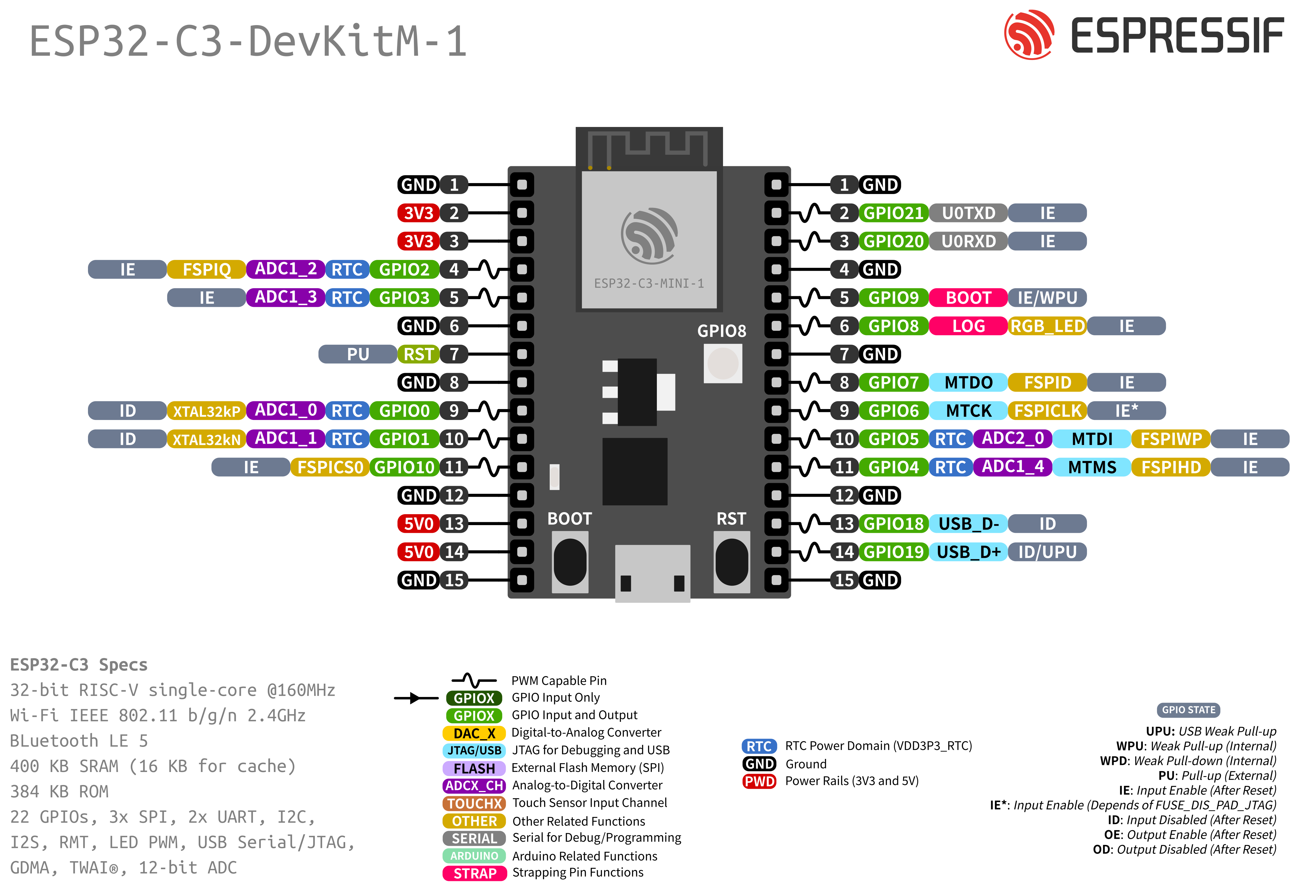
Strapping Pins
Some of the GPIO’s have important features during the booting process. Here is the list of the strapping pins on the ESP32-C3.
GPIO |
Default |
Function |
Pull-up |
Pull-down |
|---|---|---|---|---|
IO2 |
N/A |
Booting Mode |
See ESP32-C3 |
See ESP32-C3 |
IO9 |
Pull-up |
Booting Mode |
SPI Boot |
Download Boot |
IO8 |
N/A |
Booting Mode |
Don’t Care |
Download Boot |
IO8 |
Pull-up |
Enabling/Disabling Log Print |
See ESP32-C3 |
See ESP32-C3 |
For more detailed information, see the ESP32-C3 datasheet.
Resources
ESP32-C3 (Datasheet)
ESP32-C3-MINI-1 (Datasheet)