ESP32-DevKitC-1
The ESP32-DevKitC-1 development board is one of Espressif’s official boards. This board is based on the ESP32-WROVER-E module, with the ESP32 as the core.
Specifications
Wi-Fi 802.11b/g/n (802.11n up to 150 Mbps)
Bluetooth v4.2 BR/EDR and BLE specification
Built around ESP32 series of SoCs
Integrated 4 MB SPI flash
Integrated 8 MB PSRAM
- Peripherals
SD card
UART
SPI
SDIO
I2C
LED PWM
Motor PWM
I2S
IR
Pulse Counter
GPIO
Capacitive Touch Sensor
ADC
DAC
Two-Wire Automotive Interface (TWAI®, compatible with ISO11898-1)
PCB antenna or external antenna connector
Header Block
Note
Not all of the chip pins are exposed to the pin headers.
J1
No. |
Name |
Type |
Function |
|---|---|---|---|
1 |
3V3 |
P |
3.3 V power supply |
2 |
EN |
I |
CHIP_PU, Reset |
3 |
IO36 |
I |
GPIO36, ADC1_CH0, S_VP |
4 |
IO39 |
I |
GPIO39, ADC1_CH3, S_VN |
5 |
IO34 |
I |
GPIO34, ADC1_CH6, VDET_1 |
6 |
IO35 |
I |
GPIO35, ADC1_CH7, VDET_2 |
7 |
IO32 |
I/O |
GPIO32, ADC1_CH4, TOUCH_CH9, XTAL_32K_P |
8 |
IO33 |
I/O |
GPIO33, ADC1_CH5, TOUCH_CH8, XTAL_32K_N |
9 |
IO25 |
I/O |
GPIO25, ADC1_CH8, DAC_1 |
10 |
IO26 |
I/O |
GPIO26, ADC2_CH9, DAC_2 |
11 |
IO27 |
I/O |
GPIO27, ADC2_CH7, TOUCH_CH7 |
12 |
IO14 |
I/O |
GPIO14, ADC2_CH6, TOUCH_CH6, MTMS |
13 |
IO12 |
I/O |
GPIO12, ADC2_CH5, TOUCH_CH5, MTDI |
14 |
GND |
G |
Ground |
15 |
IO13 |
I/O |
GPIO13, ADC2_CH4, TOUCH_CH4, MTCK |
16 |
IO9 |
I/O |
GPIO9, D2 |
17 |
IO10 |
I/O |
GPIO10, D3 |
18 |
IO11 |
I/O |
GPIO11, CMD |
19 |
5V0 |
P |
5 V power supply |
J3
No. |
Name |
Type |
Function |
|---|---|---|---|
1 |
GND |
G |
Ground |
2 |
IO23 |
I/O |
GPIO23 |
3 |
IO22 |
I/O |
GPIO22 |
4 |
IO1 |
I/O |
GPIO1, U0TXD |
5 |
IO3 |
I/O |
GPIO3, U0RXD |
6 |
IO21 |
I/O |
GPIO21 |
7 |
GND |
G |
Ground |
8 |
IO19 |
I/O |
GPIO19 |
9 |
IO18 |
I/O |
GPIO18 |
10 |
IO5 |
I/O |
GPIO5 |
11 |
IO17 |
I/O |
GPIO17 |
12 |
IO16 |
I/O |
GPIO16 |
13 |
IO4 |
I/O |
GPIO4, ADC2_CH0, TOUCH_CH0 |
14 |
IO0 |
I/O |
GPIO0, ADC2_CH1, TOUCH_CH1, Boot |
16 |
IO2 |
I/O |
GPIO2, ADC2_CH2, TOUCH_CH2 |
17 |
IO15 |
I/O |
GPIO15, ADC2_CH3, TOUCH_CH3, MTDO |
17 |
IO8 |
I/O |
GPIO8, D1 |
18 |
IO7 |
I/O |
GPIO7, D0 |
19 |
IO6 |
I/O |
GPIO6, SCK |
P: Power supply; I: Input; O: Output; T: High impedance.
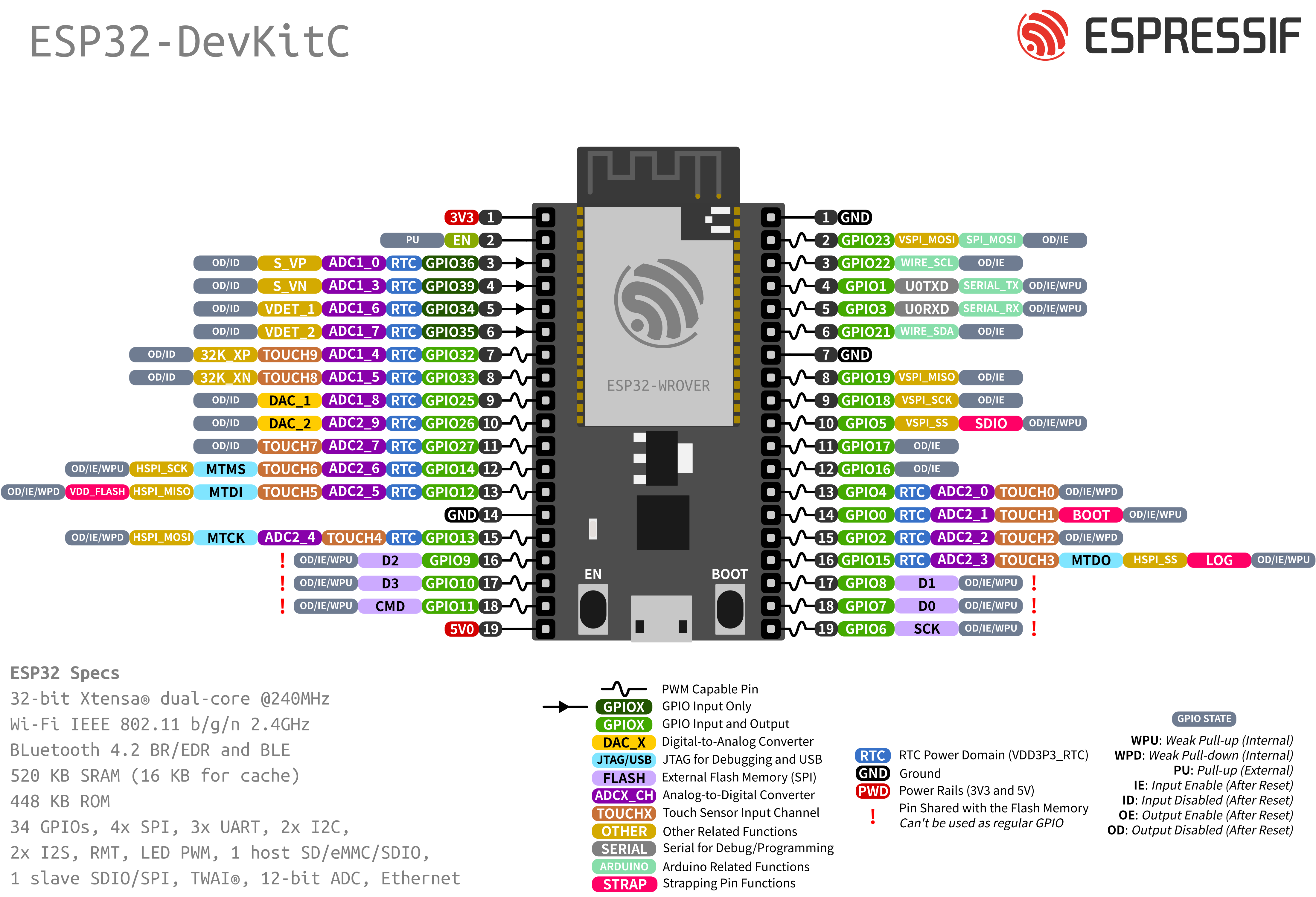
Pin Layout
Strapping Pins
Some of the GPIO’s have important features during the booting process. Here is the list of the strapping pins on the ESP32.
GPIO |
Default |
Function |
Pull-up |
Pull-down |
|---|---|---|---|---|
IO12 |
Pull-down |
Voltage of Internal LDO (VDD_SDIO) |
1.8 V |
3.3 V |
IO0 |
Pull-up |
Booting Mode |
SPI Boot |
Download Boot |
IO2 |
Pull-down |
Booting Mode |
Don’t Care |
Download Boot |
IO15 |
Pull-up |
Enabling/Disabling Log Print During Booting and Timing of SDIO Slave |
U0TXD Active |
U0TXD Silent |
IO5 |
Pull-up |
Timing of SDIO Slave |
See ESP32 |
See ESP32 |
Be aware when choosing which pins to use.
Restricted Usage GPIO’s
Some of the GPIO’s are used for the external flash and PSRAM. These GPIO’s cannot be used:
GPIO |
Shared Function |
|---|---|
IO6 |
External SPI Flash |
IO7 |
External SPI Flash |
IO8 |
External SPI Flash |
IO9 |
External SPI Flash |
IO10 |
External SPI Flash |
IO11 |
External SPI Flash |
Other GPIO’s are INPUT ONLY and cannot be used as output pin:
GPIO |
Function |
|---|---|
IO34 |
GPIO34, ADC1_CH6, VDET_1 |
IO35 |
GPIO35, ADC1_CH7, VDET_2 |
IO36 |
GPIO36, ADC1_CH0, S_VP |
IO39 |
GPIO39, ADC1_CH3, S_VN |
Resources
ESP32 (Datasheet)
ESP32-WROVER-E (Datasheet)
ESP32-DevKitC (Schematic)