GPIO Matrix and Pin Mux
Introduction
This is a basic introduction to how the peripherals work in the ESP32. This tutorial can be used to understand how to define the peripheral usage and its corresponding pins.
In some microcontrollers’ architecture, the peripherals are attached to specific pins and cannot be redefined to another one.
For example:
The XYZ MCU defines that the I2C peripheral SDA signal is the IO5 on the physical pin 10 and the SCL is on the IO6 and physical pin 11.
This means that, in your hardware project, you NEED to use these pins as the I2C and this cannot be changed due to the internal architecture. In this case, you must be very careful during the hardware design to not make any mistake by switching the SDA and SCL connections. Firmware will not help you if you do so.
GPIO Matrix and Pin Mux
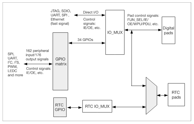
The ESP32 architecture includes the capability of configuring some peripherals to any of the GPIOs pins, managed by the IO MUX GPIO. Essentially, this capability means that we can route the internal peripheral into a different physical pin using the IO MUX and the GPIO Matrix.
It means that in the scenario of the XYZ MCU, in the ESP32 we can use any of the GPIOs to route the SDA (input/output) and the SCL (output).
To use this functionality, we must be aware of some precautions:
Some of the GPIOs are INPUT only.
Some peripherals have output signals and must be used on GPIO’s capable to be configured as OUTPUT.
Some peripherals, mostly the high speed ones, ADC, DAC, Touch, and JTAG use dedicated GPIOs pins.
Some pins are used to connect flash memory on the module - this prevents them from any other use - if a peripheral is routed to one of these pins the device will not be able to boot.
Warning
Before assigning the peripheral pins in your design, double check if the pins you’re using are appropriate. The input-only pins cannot be used for peripherals that require output or input/output signals.
The greatest advantage of this functionality is the fact that we don’t need to be fully dependent on the physical pin, since we can change according to our needs. This can facilitate the hardware design routing or in some cases, fix some pin swap mistake during the hardware design phase.
Peripherals
Here is the basic peripherals list present on the ESP32. The peripheral list may vary from each ESP32 SoC family. To see all peripherals available on the ESP32-S2 and ESP32-C3, check each of the datasheets.
Peripheral Table
Type |
Function |
|---|---|
ADC |
Dedicated GPIOs |
DAC |
Dedicated GPIOs |
Touch Sensor |
Dedicated GPIOs |
JTAG |
Dedicated GPIOs |
SD/SDIO/MMC HostController |
Dedicated GPIOs |
Motor PWM |
Any GPIO |
SDIO/SPI SlaveController |
Dedicated GPIOs |
UART |
Any GPIO[1] |
I2C |
Any GPIO |
I2S |
Any GPIO |
LED PWM |
Any GPIO |
RMT |
Any GPIO |
GPIO |
Any GPIO |
Parallel QSPI |
Dedicated GPIOs |
EMAC |
Dedicated GPIOs |
Pulse Counter |
Any GPIO |
TWAI |
Any GPIO |
USB |
Dedicated GPIOs |
[1] except for the download/programming mode decided by the bootloader.
This table is present on each datasheet provided by Espressif.
Usage Examples
In the Arduino Uno, we have the I2C pins defined by hardware, A4 is the SDA and A5 the SCL. In this case, we do not need to set
these pins in the Wire.begin(); function, because they are already into the Wire library.
void setup()
{
    Wire.begin(); // join i2c bus (address optional for master)
}
Now, for the ESP32, the default pins for the I2C are SDA (GPIO21) and SCL (GPIO22). We can use a different pin as alternative for the
default ones if you need to change the pins.
To change the pins, we must call the Wire.setPins(int sda, int scl); function before calling Wire.begin();.
int sda_pin = 16; // GPIO16 as I2C SDA
int scl_pin = 17; // GPIO17 as I2C SCL

void setup()
{
    Wire.setPins(sda_pin, scl_pin); // Set the I2C pins before begin
    Wire.begin(); // join i2c bus (address optional for master)
}
A similar approach also applies for the other peripherals.