ESP32-P4X-C5-Function-EV-Board
This user guide will help you get started with ESP32-P4X-C5-Function-EV-Board and will also provide more in-depth information.
The document consists of the following major sections:
Board Overview: A brief introduction to the board’s software and hardware
Start Application Development: Hardware and software setup for application development
Hardware Reference: Detailed information about the board’s hardware
Hardware Revision Details: Hardware revision history and known issues, with links to user guides for previous board versions (if any)
Related Documents: Links to related documentation
Disclaimer and Copyright Notice: Link to the disclaimer and copyright notice.
Board Overview
ESP32-P4X-C5-Function-EV-Board is a multimedia development board based on the ESP32-P4 chip. ESP32-P4 features a dual-core RISC-V processor and supports up to 32 MB PSRAM. In addition, ESP32-P4 supports USB 2.0 specification, MIPI-CSI/DSI, H264 Encoder, and various other peripherals, meeting the development needs of low-cost, high-performance, low-power multimedia products.
The board is equipped with the ESP32-C5-MINI-1 module, which supports 2.4 GHz & 5 GHz dual-band Wi-Fi 6 and Bluetooth 5 (LE) for Wi-Fi and Bluetooth communication. The board also includes a 7-inch capacitive touch screen with a resolution of 1024 x 600 and a 2MP camera with MIPI CSI, enriching the user interaction experience. The development board is suitable for prototyping a wide range of products, including visual doorbells, network cameras, smart home central control screens, LCD electronic price tags, two-wheel vehicle dashboards, etc.
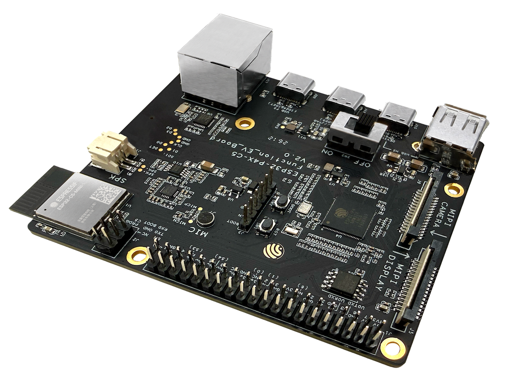
ESP32-P4X-C5-Function-EV-Board (with ESP32-C5-MINI-1 module)
Feature List
The board has the following features:
Main SoC: ESP32-P4, a dual-core RISC-V processor with 16 MB SPI flash and 32 MB PSRAM on board
On-board Module: ESP32-C5-MINI-1, supports 2.4 GHz & 5 GHz dual-band Wi-Fi 6, Bluetooth 5 (LE), and IEEE 802.15.4
Display: MIPI DSI interface, can connect a 7-inch capacitive touch screen (1024 × 600)
Camera: MIPI CSI interface, can connect a 2MP camera
Audio: ES8311 audio codec chip, NS4150B audio power amplifier, onboard microphone, speaker output port
Storage: MicroSD card slot (4-bit mode)
USB: USB 2.0 OTG Type-C port, USB 2.0 Type-A port, USB Full-Speed port, USB Serial/JTAG port
Network: RJ45 Ethernet port (10/100 Mbps adaptive)
Expansion: J1 header with available GPIO pins broken out
Buttons: BOOT button and Reset button
Block Diagram
The block diagram below shows the components of ESP32-P4X-C5-Function-EV-Board and their interconnections.
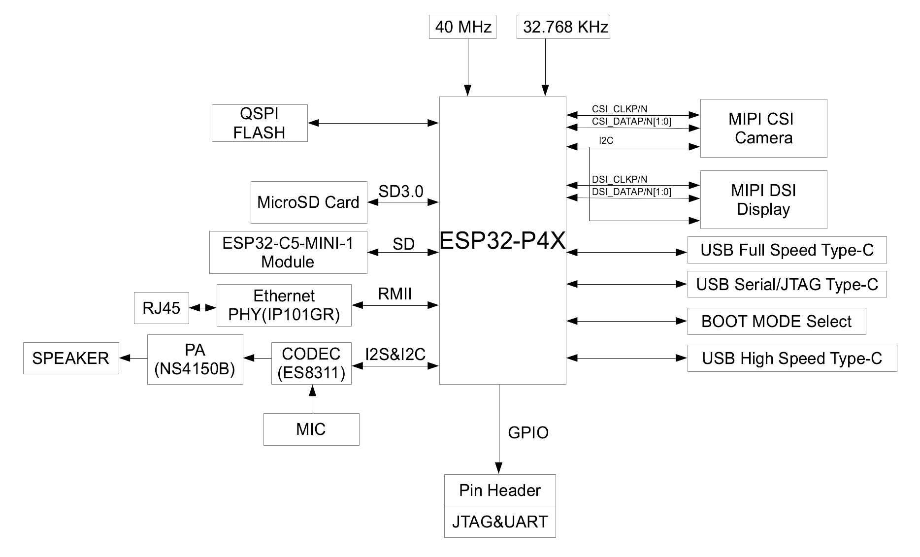
ESP32-P4X-C5-Function-EV-Board block diagram
Description of Components
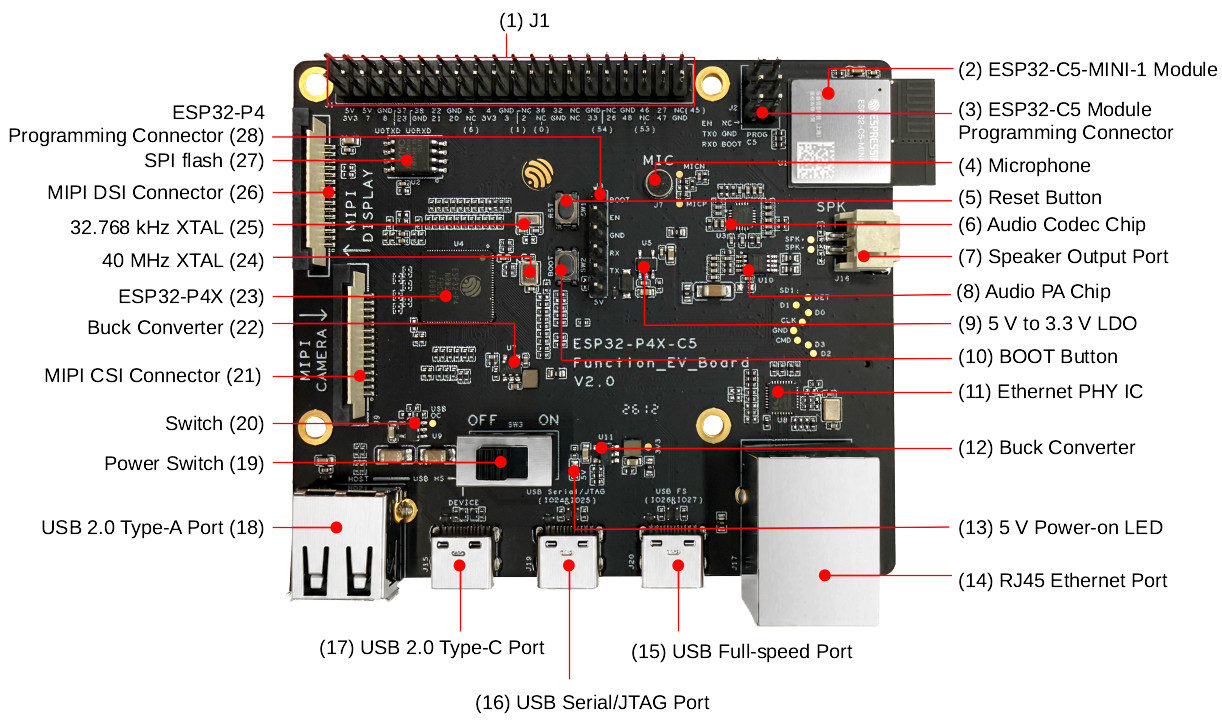
ESP32-P4X-C5-Function-EV-Board - front
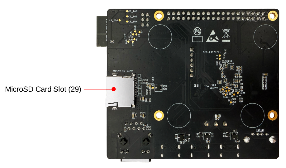
ESP32-P4X-C5-Function-EV-Board - back
The key components on the front and back of the board are described below, starting from J1 and proceeding clockwise.
No. |
Key Component |
Description |
|---|---|---|
1 |
J1 |
All available GPIO pins are broken out to the header block J1 for easy interfacing. For more details, see Header Block. |
2 |
ESP32-C5-MINI-1 Module |
This module serves as the Wi-Fi and Bluetooth communication module for the board. |
3 |
ESP32-C5 Module Programming Connector |
The connector can be used with ESP-Prog or other UART tools to flash firmware onto the ESP32-C5 module. |
4 |
Microphone |
Onboard microphone connected to the Audio Codec Chip. |
5 |
Reset Button |
Resets the board. |
6 |
Audio Codec Chip |
ES8311 is a low-power mono audio codec chip. It includes a single-channel ADC, a single-channel DAC, a low-noise pre-amplifier, a headphone driver, digital sound effects, analog mixing, and gain functions. It interfaces with the ESP32-P4 chip over I2S and I2C buses to provide hardware audio processing independent of the audio application. |
7 |
Speaker Output Port |
This port is used to connect a speaker. The maximum output power can drive a 4 Ω, 3 W speaker. The pin spacing is 2.00 mm (0.08”). |
8 |
Audio PA Chip |
NS4150B is a low EMI, 3 W mono Class D audio power amplifier that amplifies audio signals from the audio codec chip to drive speakers. |
9 |
5 V to 3.3 V LDO |
A power regulator that converts a 5 V supply to a 3.3 V output. |
10 |
BOOT Button |
The boot mode control button. Press the Reset Button while holding down the BOOT Button to reset ESP32-P4 and enter firmware download mode. Firmware can then be downloaded to onboard SPI flash via the USB Serial/JTAG Port. |
11 |
Ethernet PHY IC |
Ethernet PHY chip IP101GR connected to the ESP32-P4 EMAC RMII interface and RJ45 Ethernet Port. |
12 |
Buck Converter |
A buck DC-DC converter for the 3.3 V power supply. |
13 |
5 V Power-on LED |
This LED lights up when the board is powered through any USB Type-C port. |
14 |
RJ45 Ethernet Port |
Ethernet port supporting 10/100 Mbps adaptive. |
15 |
USB Full-speed Port |
USB Type-C port that supports USB 2.0 Full-speed data rate. It can be used to power the board and serve as a communication interface. |
16 |
USB Serial/JTAG Port |
USB Type-C port that supports USB 2.0 Full-speed data rate. It can be used to flash firmware to the ESP32-P4 chip, communicate with the chip via the USB protocol, and perform JTAG debugging. |
17 |
USB 2.0 Type-C Port |
The USB 2.0 Type-C Port is connected to the USB 2.0 OTG High-Speed interface of ESP32-P4, compliant with the USB 2.0 specification. When communicating with other devices via this port, ESP32-P4 acts as a USB device connecting to a USB host. Please note that the USB 2.0 Type-C Port and USB 2.0 Type-A Port cannot be used simultaneously. This port can also be used for powering the board. |
18 |
USB 2.0 Type-A Port |
The USB 2.0 Type-A Port is connected to the USB 2.0 OTG High-Speed interface of ESP32-P4, compliant with the USB 2.0 specification. When communicating with other devices via this port, ESP32-P4 acts as a USB host, providing up to 500 mA of current. Please note that the USB 2.0 Type-C Port and USB 2.0 Type-A Port cannot be used simultaneously. |
No. |
Key Component |
Description |
|---|---|---|
19 |
Power Switch |
Power On/Off Switch. Toggling toward the ON sign powers the board on (5 V); toggling away from the ON sign powers the board off. |
20 |
Switch |
TPS2051C is a USB power switch. When the USB 2.0 Type-A port is used for ESP32-P4 as a USB host to connect external USB devices, power must be supplied to those devices. TPS2051C limits the external supply current to within 500 mA, complying with the USB specification and preventing external devices from drawing excessive current. It also protects the development board from damage caused by short circuits or overloads on external devices. |
21 |
MIPI CSI Connector |
The FPC connector 1.0K-GT-15PB is used for connecting external camera modules to enable image transmission. For details, please refer to the 1.0K-GT-15PB specification in Related Documents. FPC specifications: 1.0 mm pitch, 0.7 mm pin width, 0.3 mm thickness, 15 pins. |
22 |
Buck Converter |
A buck DC-DC converter for the VDD_HP power supply of ESP32-P4. |
23 |
ESP32-P4 |
A high-performance MCU with large internal memory and powerful image and voice processing capabilities. |
24 |
40 MHz XTAL |
40 MHz crystal oscillator that provides the system clock. |
25 |
32.768 kHz XTAL |
32.768 kHz crystal oscillator that provides a low-power clock for Deep-sleep mode. |
26 |
MIPI DSI Connector |
The FPC connector 1.0K-GT-15PB is used for connecting the LCD adapter board. For details, please refer to the 1.0K-GT-15PB specification in Related Documents. FPC specifications: 1.0 mm pitch, 0.7 mm pin width, 0.3 mm thickness, 15 pins. |
27 |
SPI flash [1] |
16 MB flash connected to the ESP32-P4 chip via the SPI interface. |
28 |
ESP32-P4 Programming Connector |
The connector can be used with ESP-Prog or other UART tools to flash firmware onto the ESP32-P4 chip revision v3.x and later. |
29 |
MicroSD Card Slot |
The development board supports a MicroSD card in 4-bit mode and can store or play audio files from the MicroSD card. |
Note
Usage notes for LDO_VO3 / LDO_VO4:
On the ESP32-P4X-C5-Function-EV-Board, LDO_VO3 and LDO_VO4 are used to power certain on-board VDD domains. Users must configure the correct output voltage and enable state in software.
In Light-sleep or Deep-sleep mode, if LDO_VO3 / LDO_VO4 remain enabled, the system power consumption will be relatively high. Even when turned off, the total power consumption may still exceed the typical low-power specifications listed in the chip datasheet due to the board-level power architecture.
For applications with strict power consumption requirements, it is recommended to optimize the power architecture in custom hardware designs.
Accessories
Optionally, the following accessories are included in the package:
LCD and its accessories (optional)
7-inch capacitive touch screen with a resolution of 1024 x 600
LCD adapter board
Accessories bag, including DuPont wires, ribbon cable for LCD, long brass standoffs (20 mm in length), and short brass standoffs (8 mm in length)
Camera and its accessories (optional)
2MP camera with MIPI CSI
Camera adapter board
Ribbon cable for camera
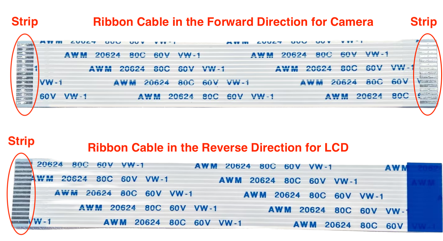
Ribbon Cables in Forward and Reverse Directions
Note
Please note that the ribbon cable in the forward direction, whose strips at the two ends are on the same side, should be used for the camera; the ribbon cable in the reverse direction, whose strips at the two ends are on different sides, should be used for the LCD.
Application Examples
The following application examples are available for ESP32-P4X-C5-Function-EV-Board:
ESP_Brookesia Phone - Demonstrates an Android-like interface with multiple applications using ESP_Brookesia, utilizing MIPI-DSI, MIPI-CSI, ESP32-C5, SD card, and audio interfaces on the development board, providing a basis for efficient multimedia application development.
Alternatively, you can try the factory demo and other prebuilt examples directly in your web browser using ESP Launchpad. ESP Launchpad provides a convenient way to flash firmware to your board without installing ESP-IDF or compiling the source code.
To explore the application examples or to develop your own, please follow the steps outlined in the Start Application Development section.
Start Application Development
This section describes how to set up the hardware and software, and how to flash firmware onto the development board for application development.
Required Hardware
ESP32-P4X-C5-Function-EV-Board
USB cable
Computer running Windows, Linux, or macOS
Note
Be sure to use a USB cable that supports data transfer. Some cables are for charging only and cannot be used for data transfer or programming.
Optional Hardware
MicroSD card
Power Supply Options
The board can be powered in any of the following three ways:
Via the USB 2.0 Type-C Port
Via the USB Full-speed Port
Via the USB Serial/JTAG Port
If the USB cable used for debugging cannot provide enough current, you can connect the board to a power adapter via any USB Type-C port.
Hardware Setup
Connect the ESP32-P4X-C5-Function-EV-Board to your computer using a USB cable. The board can be powered through any of the USB Type-C ports. The USB Serial/JTAG Port is recommended for flashing firmware and debugging.
To connect the LCD, follow these steps:
Secure the development board to the LCD adapter board by attaching the short brass standoffs to the four standoff posts at the center of the LCD adapter board.
Connect the J3 header of the LCD adapter board to the MIPI DSI connector on the ESP32-P4X-C5-Function-EV-Board using the LCD ribbon cable (reverse direction). Note that the LCD adapter board is already connected to the LCD.
Use a DuPont wire to connect the GPIO27 pin of the J1 header on the ESP32-P4X-C5-Function-EV-Board to the RST_LCD pin of the J6 header on the LCD adapter board. The GPIO mapped to RST_LCD can be configured via software, with GPIO27 set as the default.
Use a DuPont wire to connect the GPIO26 pin of the J1 header on the ESP32-P4X-C5-Function-EV-Board to the PWM pin of the J6 header on the LCD adapter board. The GPIO mapped to PWM can be configured via software, with GPIO26 set as the default.
It is recommended to power the LCD by connecting a USB cable to the J1 header of the LCD adapter board. If this is not feasible, use DuPont wires to connect the 5V and GND pins of the J1 header on the ESP32-P4X-C5-Function-EV-Board to the 5V and GND pins of the LCD adapter board, provided that the development board has sufficient power supply.
In summary, the ESP32-P4X-C5-Function-EV-Board and the LCD adapter board are connected via the following pins:
ESP32-P4X-C5-Function-EV-Board |
LCD Adapter Board |
|---|---|
MIPI DSI connector |
J3 header |
GPIO27 pin of J1 header |
RST_LCD pin of J6 header |
GPIO26 pin of J1 header |
PWM pin of J6 header |
5V pin of J1 header |
5V pin of J6 header |
GND pin of J1 header |
GND pin of J6 header |
Attach the long brass standoffs to the four standoff posts on the periphery of the LCD adapter board to allow the LCD to stand upright.
Note
If you power the LCD adapter board by connecting a USB cable to its J1 header, you do not need to connect its 5V and GND pins to the corresponding pins on the development board.
To use the camera, connect the camera adapter board to the MIPI CSI connector on the development board using the camera ribbon cable (forward direction).
Software Setup
After completing the hardware setup, please follow ESP-IDF Get Started to set up your development environment and flash an application onto your board.
Hardware Reference
Header Block
The table below provides the Name and Function of the pin header J1 of the board. The pin header names are shown in Figure ESP32-P4X-C5-Function-EV-Board - front. The numbering is the same as in the ESP32-P4X-C5-Function-EV-Board Schematics.
J1
No. |
Name |
Type [2] |
Function |
|---|---|---|---|
1 |
3V3 |
P |
3.3 V power supply |
2 |
5V |
P |
5 V power supply |
3 |
7 |
I/O/T |
GPIO7 |
4 |
5V |
P |
5 V power supply |
5 |
8 |
I/O/T |
GPIO8 |
6 |
GND |
GND |
Ground |
7 |
23 |
I/O/T |
GPIO23 |
8 |
37 |
I/O/T |
U0TXD, GPIO37 |
9 |
GND |
GND |
Ground |
10 |
38 |
I/O/T |
U0RXD, GPIO38 |
11 |
21 |
I/O/T |
GPIO21 |
12 |
22 |
I/O/T |
GPIO22 |
13 |
20 |
I/O/T |
GPIO20 |
14 |
GND |
GND |
Ground |
15 |
NC(6) |
I/O/T |
GPIO6 [3] |
16 |
5 |
I/O/T |
GPIO5 |
17 |
3V3 |
P |
3.3 V power supply |
18 |
4 |
I/O/T |
GPIO4 |
19 |
3 |
I/O/T |
GPIO3 |
20 |
GND |
GND |
Ground |
21 |
2 |
I/O/T |
GPIO2 |
22 |
NC(1) |
I/O/T |
GPIO1 [4] |
23 |
NC(0) |
I/O/T |
GPIO0 [4] |
24 |
36 |
I/O/T |
GPIO36 |
25 |
GND |
GND |
Ground |
26 |
32 |
I/O/T |
GPIO32 |
27 |
NC |
– |
No connection |
28 |
NC |
– |
No connection |
29 |
33 |
I/O/T |
GPIO33 |
30 |
GND |
GND |
Ground |
31 |
26 |
I/O/T |
GPIO26 |
32 |
NC(54) |
I/O/T |
GPIO54 [5] |
33 |
48 |
I/O/T |
GPIO48 |
34 |
GND |
GND |
Ground |
35 |
NC(53) |
I/O/T |
GPIO53 [6] |
36 |
46 |
I/O/T |
GPIO46 |
37 |
47 |
I/O/T |
GPIO47 |
38 |
27 |
I/O/T |
GPIO27 |
39 |
GND |
GND |
Ground |
40 |
NC(45) |
I/O/T |
GPIO45 [7] |
Hardware Revision Details
No previous revisions.