Please check the silkscreen version number on the mainboard to confirm your development board version. For v1.0 version development boards, please refer to the current user guide; for v1.2 version development boards, please refer to EchoEar v1.2.
This guide will help you get started with EchoEar quickly and provide detailed information about this development board.
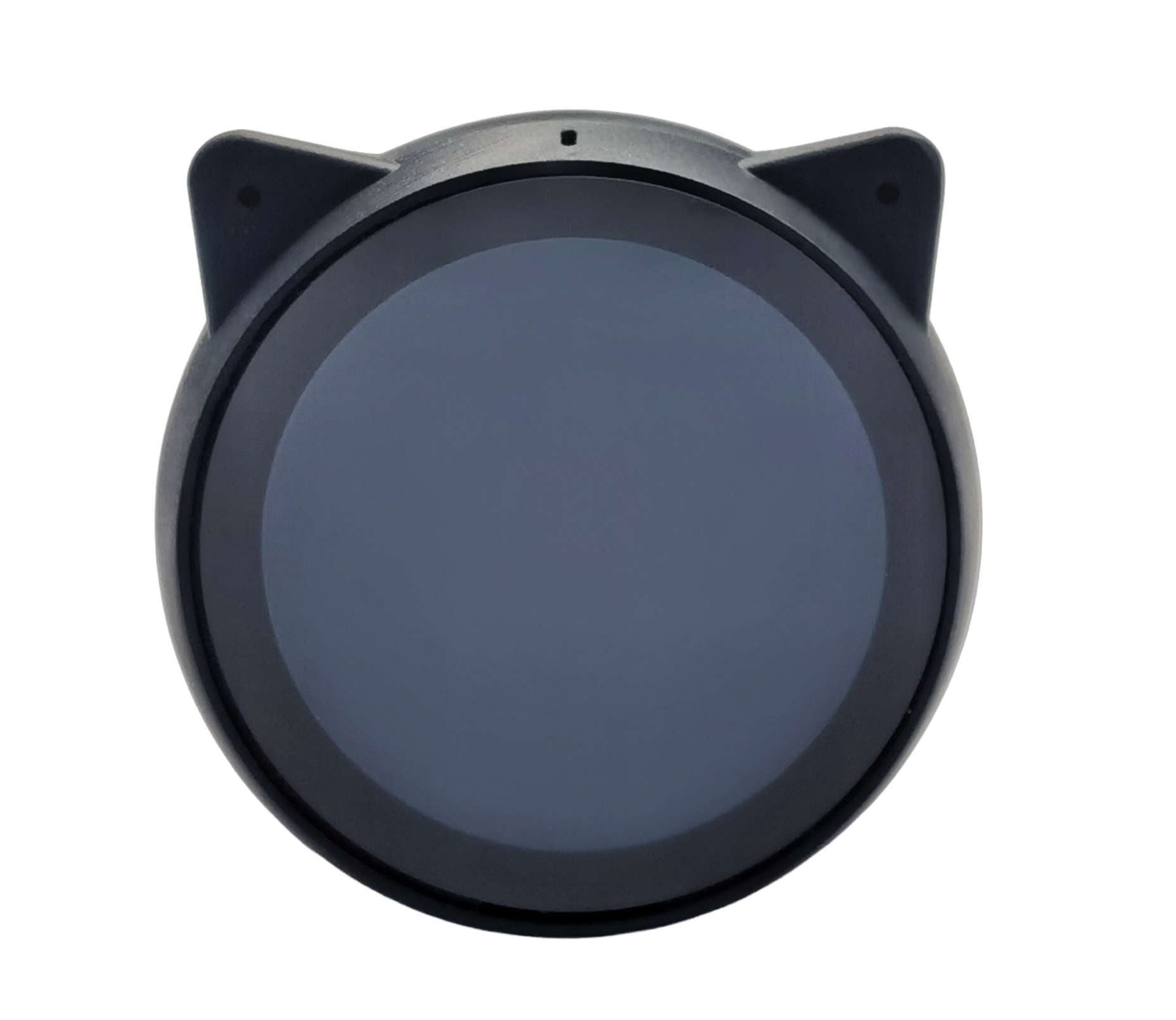
EchoEar is an intelligent AI development kit. It is suitable for voice interaction products that require large model capabilities, such as toys, smart speakers, and smart central control systems. The device is equipped with a 1.85-inch QSPI circular touch screen, dual microphone array, and supports offline voice wake-up and sound source localization algorithms. Combined with the large model capabilities provided by OpenAI,Xiaozhi AI, Gemini, etc., EchoEar can achieve full-duplex voice interaction, multimodal recognition, and intelligent agent control, providing a solid foundation for developers to create complete edge-side AI application experiences.
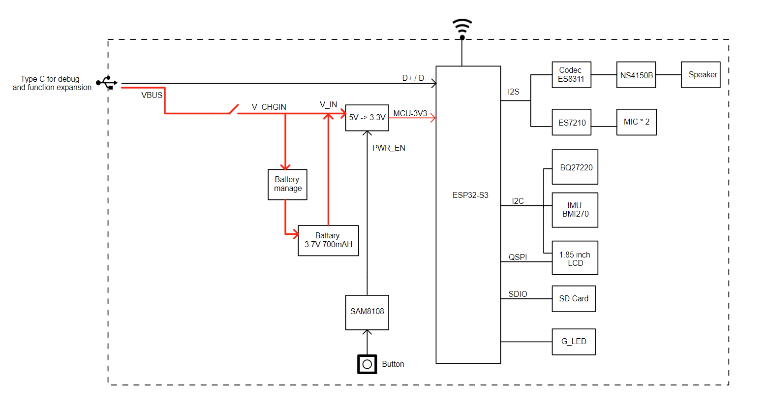
EchoEar’s main controller uses the Espressif ESP32-S3-WROOM-2-N32R16V module, supporting 2.4 GHz Wi-Fi and Bluetooth 5 (LE) wireless connectivity. For storage, the entire device has 16 MB PSRAM and 32 MB Flash storage space, and is also equipped with a microSD card slot that can support up to 32 GB, meeting the needs of voice interaction and multimedia processing. It features a 1.85-inch circular touch screen (360 × 360 resolution) with ESP32-S3 native touch sensors, providing an intuitive and rich interactive experience.
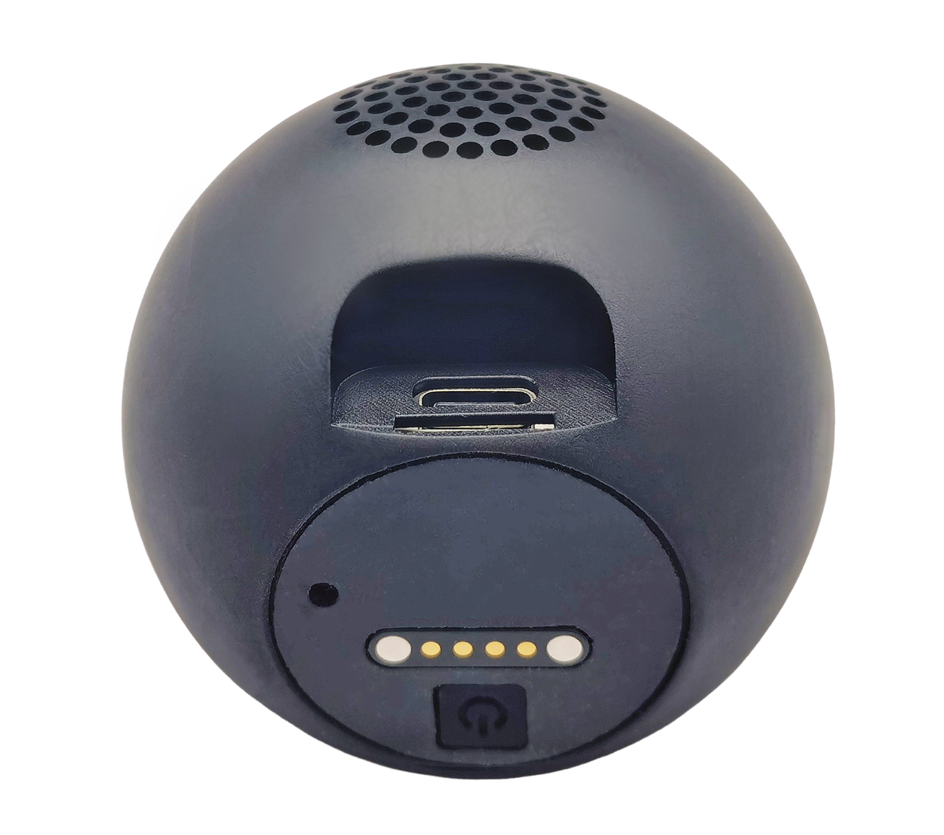
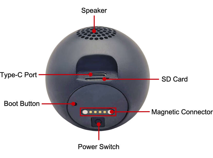
For audio, EchoEar has a built-in 3W speaker and dual microphone array, supporting local voice wake-up and sound source localization. The power system is compatible with 5 V DC and 3.7 V lithium battery power supply. Additionally, it integrates a USB-C interface for power supply and programming download, while reserving a Pogopin interface for convenient functional expansion.
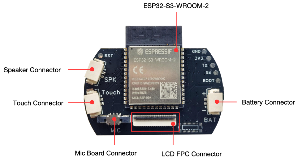
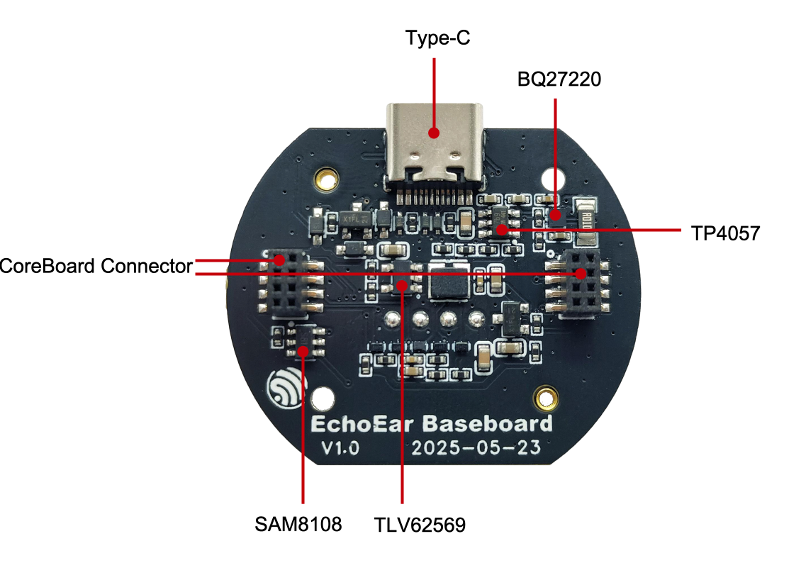
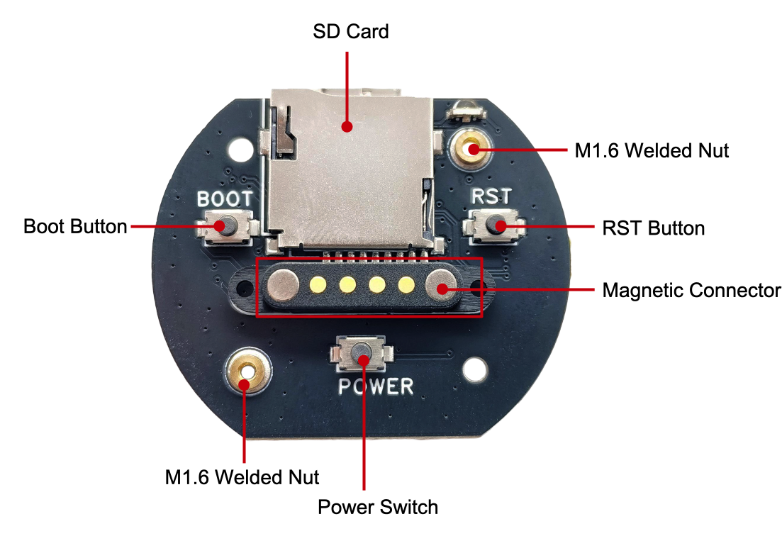
The following introduces the main components on the front PCB in clockwise order. For user convenience, we have also labeled these components or interfaces on the EchoEar housing.
Main Components
Description
CoreBoard
ESP32-S3-WROOM-2-N32R16V
Main controller chip, integrates 32 MB Flash and 16 MB PSRAM, supports 2.4 GHz Wi-Fi and Bluetooth 5 (LE) wireless connectivity.
Battery Connector
Battery connector for connecting 3.7 V lithium battery, top is positive, bottom is negative.
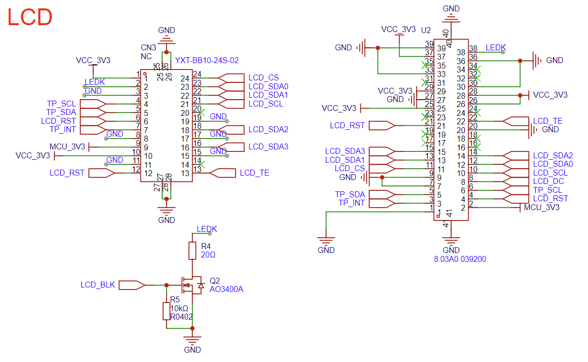
LCD FPC Connector
For connecting 1.85-inch circular LCD screen with 360 x 360 resolution. For detailed parameters, please refer to the Display Specification.
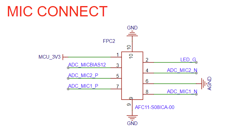
MicBoard Connector
MicBoard PCB connector, connects dual microphone array and status indicator LED.
Touch Connector
Touch connector for connecting touch copper foil to achieve touch interaction functionality.
Speaker Connector
2-wire speaker connector for connecting built-in 3 W speaker.
MicBoard
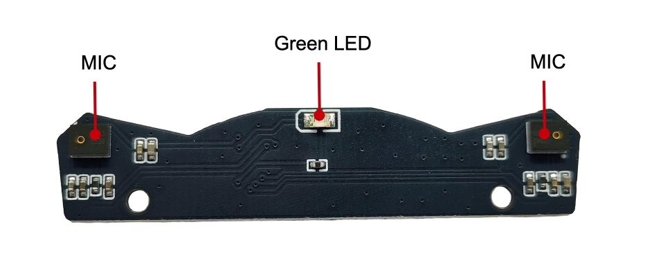
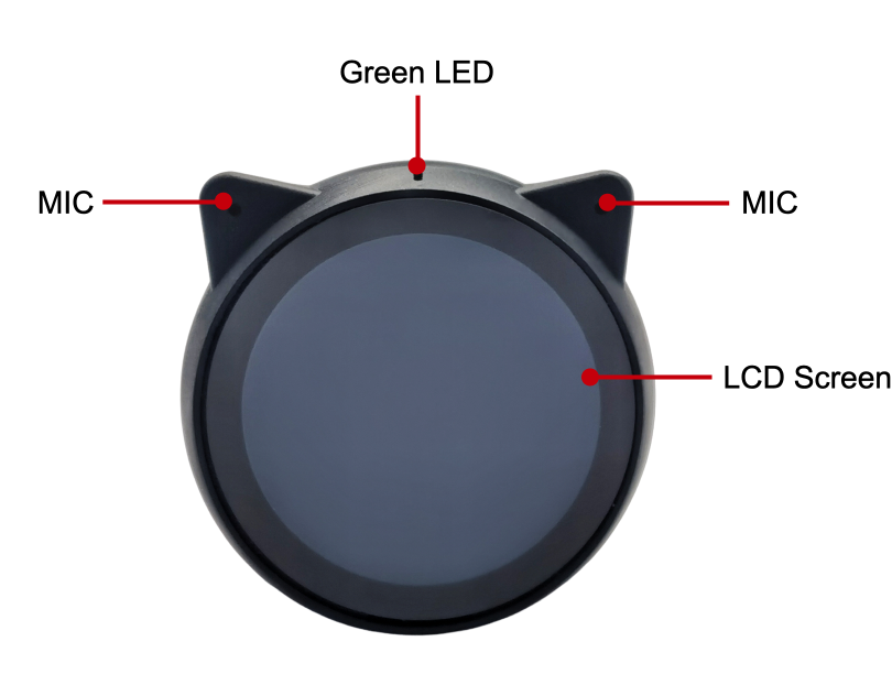
Green LED
Green LED indicator.
MIC (Microphone Array)
Dual LMA3729T381-OY3S microphone array, supports local voice wake-up and sound source localization functionality.
BaseBoard
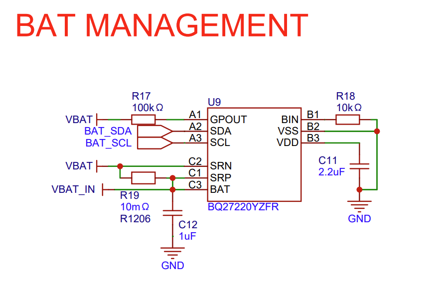
BQ27220 (Battery Management Chip)
Battery management chip for battery level detection, charging management, and power status monitoring.
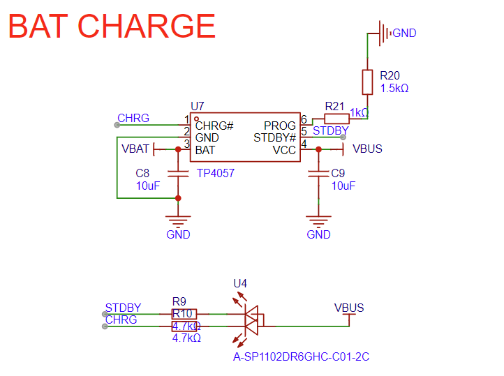
TP4057 (Lithium Battery Charging Chip)
Lithium battery charging chip for charging lithium batteries with 250 mA charging current.
CoreBoard Connector
CoreBoard PCB connector, connects core board with base board.
TlV62569 (DCDC Chip)
Buck converter chip for converting 5 V power to 3.3 V power, providing stable power supply for the system.
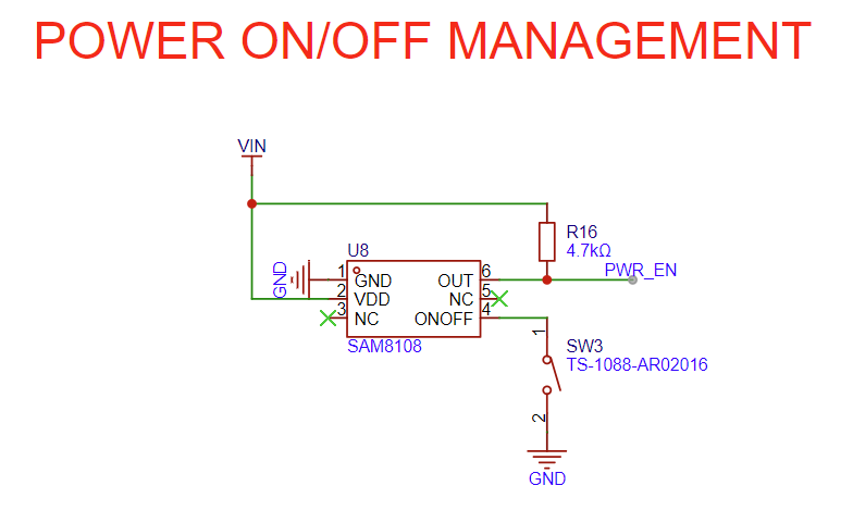
SAM8108 (Power Control Chip)
Power control chip for controlling device power on/off. Single click of POWER button can toggle power on/off status.
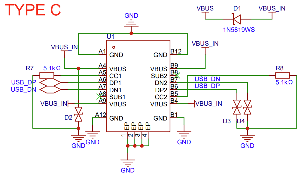
Type-C (USB-C Interface)
USB-C interface for power supply, programming download, and debugging, supports charging lithium batteries.
EchoEar CoreBoard PCB Back View (Click to enlarge)
EchoEar MicBoard PCB Back View (Click to enlarge)
EchoEar BaseBoard PCB Back View (Click to enlarge)
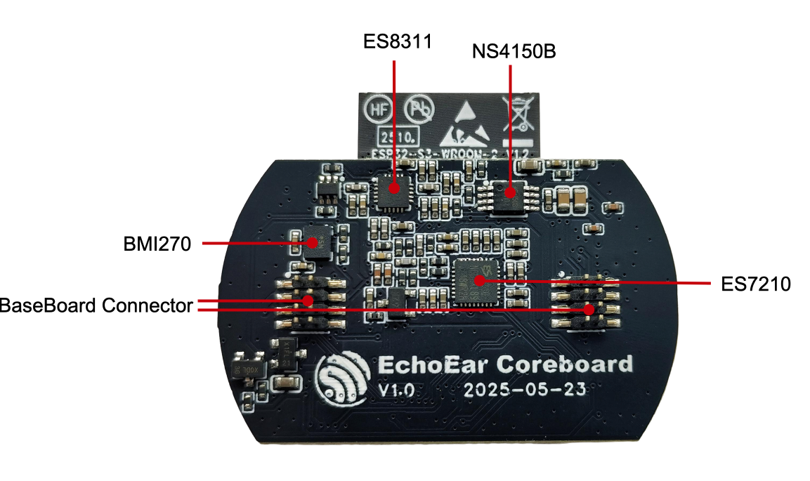
The following introduces the main components on the back PCB in clockwise order. For user convenience, we have also labeled these components or interfaces on the EchoEar housing.
Main Components
Description
CoreBoard
NS4150B (Class D Amplifier)
Ultra-low EMI, filterless, 3W mono Class D audio amplifier.
ES7210 (Audio Decoder Chip)
High-performance 4-channel audio decoder chip, supports I2S/PDM/TDM data ports.
BaseBoard Connector
Base board connector for connecting base board with CoreBoard.
BMI270 (IMU - Inertial Measurement Unit)
6-axis intelligent low-power inertial measurement unit for high-performance applications.
ES8311 (Audio Codec Chip)
Low-power mono audio codec with high-performance multi-bit Delta-Sigma audio ADC and DAC.
MicBoard
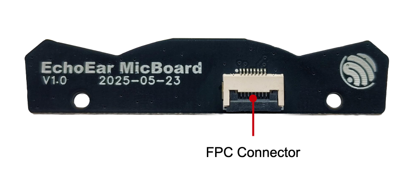
FPC Connector
Connects MicBoard with CoreBoard FPC connector.
BaseBoard
M1.6 Welded Nut
For fixing main board to housing.
RST Button (Reset Button)
For resetting the main board.
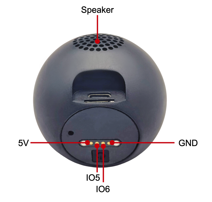
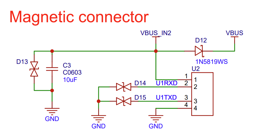
Magnetic Connector
For functional expansion, provides a serial port and 5 V power interface, can connect to rotating base and other devices.
POWER Switch
For controlling device power on/off. Single click of POWER button can toggle power on/off status.
BOOT Button
When powering on, hold this button to enter download mode.
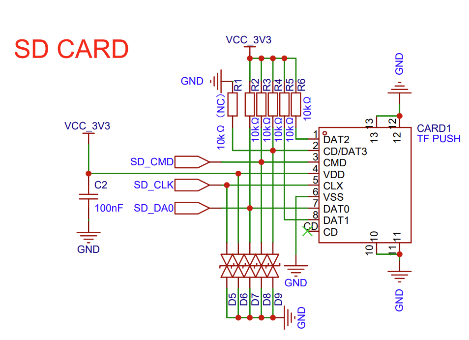
SD Card Slot
Supports up to 32 GB microSD card slot for storing audio, images, videos, and other data.
Be sure to use an appropriate USB cable. Some cables are for charging only and do not provide the needed data lines nor work for programming the boards.
Please proceed to ESP-IDF Get Started to set up the development environment and flash an application example onto your board.
Note
In most cases, USB drivers required to operate the board are already included in Windows, Linux, and macOS operating systems. Some additional port access or security configuration may be required depending on your OS. In case of issues, please check documentation on how to establish serial connection with the board. The documentation also includes links to USB drivers applicable to boards produced by Espressif.
Espressif provides Board Support Packages (BSPs) for various Espressif boards that help you initialize and use key onboard peripherals, such as LCD displays, audio chips, buttons, and LEDs, more easily and efficiently. For a complete list of supported boards, please visit esp-bsp.
Development board application examples are stored in the esp-brookesia project.
There are three mutually exclusive ways to provide power to the board:
Power through Type-C(USB-CInterface)
When using this method, connect the device’s Type-C interface using a USB Type-C data cable. If a lithium battery is installed, you need to press the POWER button to enable power supply to the device.
Power through MagneticConnector
When using this method, connect the device to the corresponding magnetic connector base to power the device. If a lithium battery is installed, you need to press the POWER button to enable power supply to the device.
Please note that the CN3 interface is reserved for other screen compatibility and is currently not enabled.
The U2 interface is the officially used LCD screen interface. The screen model used by this development board is ST77916, LCD: 1.85”, 360 x 360, ST77916, QSPI Interface. LCD_BLK (GPIO44) can be used to control screen backlight.