ESP-Mosaico Multi-function Interaction Module
This guide describes the hardware interface, installation, and software usage of the ESP-Mosaico Multi-function Interaction Module. The module connects to the left or right 2 × 10P module slot and provides ambient-light sensing, PIR motion detection, IR transmit, RGB LEDs, and key / touch input.
Note
The interaction module can be inserted into the left slot (H2, EEPROM 0x50) or the right slot (H1, EEPROM 0x51). The right slot is mounted 180° relative to the left slot. For the mainboard revision, see ESP-Mosaico V1.2 or ESP-Mosaico V1.0.
The module integrates a GL5506 photoresistor, an AS312 PIR sensor, an IR LED driven by an AO3400A, six WS2812 LEDs (four at the top and two beneath the buttons), and two pads that can be used as mechanical keys or capacitive-touch channels. An AT24C02 EEPROM identifies the module. The board type is 0x16.
This document consists of the following major sections:
Getting Started: Installation, power, and how to use the module.
Hardware Reference: Left/right pin map and peripheral notes.
Hardware Revision Details: Hardware revision history (if any).
Related Documents: Links to related documentation.
Disclaimer and Copyright Notice: Disclaimer and copyright notice.
Getting Started
Description of Components
The front view and its main components are shown first, followed by the back view.
Front
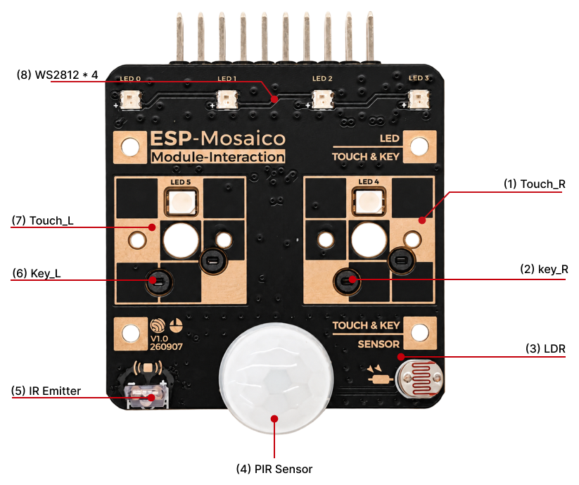
Interaction module front (Click to enlarge)
The following describes the main components on the front by callout number, in clockwise order.
No. |
Key Component |
Description |
|---|---|---|
1 |
Touch_R |
Right touch pad, usable as a capacitive-touch channel. |
2 |
key_R |
Right mechanical key, active-low. |
3 |
LDR |
GL5506 photoresistor sampled by ADC for ambient light. |
4 |
PIR Sensor |
AS312 PIR sensor that outputs a motion-detect level. |
5 |
IR Emitter |
Infrared emitter driven by AO3400A. Default protocol is NEC at 38 kHz. |
6 |
Key_L |
Left mechanical key, active-low. |
7 |
Touch_L |
Left touch pad, usable as a capacitive-touch channel. |
8 |
WS2812 × 4 |
Top LEDs LED0–LED3: four addressable RGB LEDs on a single data line. |
Back
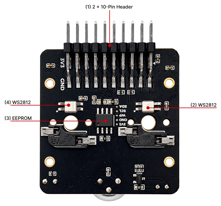
Interaction module back (Click to enlarge)
The following describes the main components on the back using the callout numbers in the figure.
No. |
Key Component |
Description |
|---|---|---|
1 |
2 × 10-Pin Header |
2 × 10P, 2.54 mm pitch header that mates with the BaseBoard left/right module slots. |
2 |
WS2812 |
Addressable RGB LED on the right side of the figure. |
3 |
EEPROM |
AT24C02 module EEPROM. Address 0x50 on the left slot and 0x51 on the right slot. Board type 0x16. |
4 |
WS2812 |
Addressable RGB LED on the left side of the figure. |
Start Using the Module
Required Hardware
ESP-Mosaico (CoreBoard V1.0 or V1.2)
ESP-Mosaico Multi-function Interaction Module
USB cable (data-capable)
Computer (Windows, Linux, or macOS)
Installation
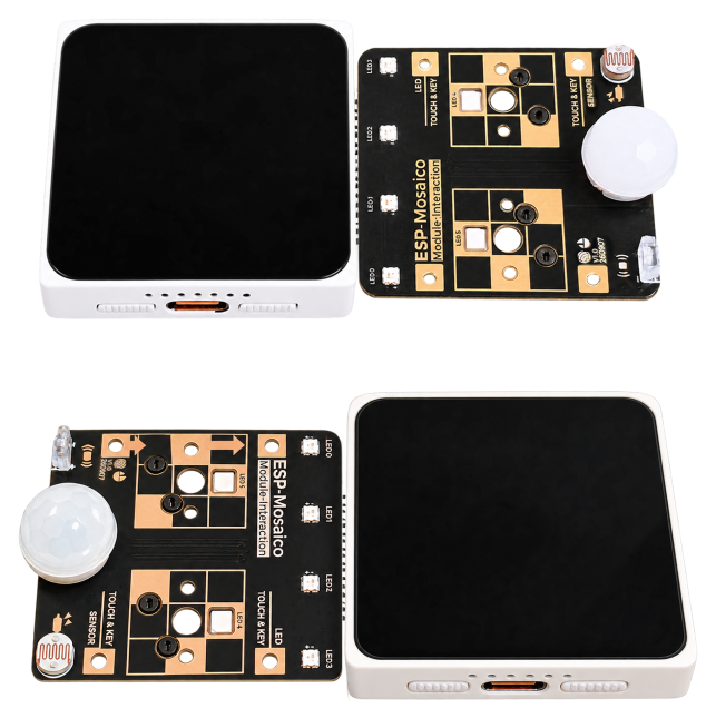
Interaction module mounting orientation (Click to enlarge)
With the host powered off, or with the external 3.3 V / 5 V outputs disabled, insert the module into the left or right module slot. Rotate the module 180° when using the right slot.
Power ESP-Mosaico from Type-C and turn it on. The expansion 3.3 V / 5 V rails are output only when GPIO60 is driven low.
After power-on, the host identifies the interaction module from its EEPROM (board type 0x16). A module without this information is not recognized.
How to Use
Once the module is recognized, the display shows a control for each inserted slot. Switch among ambient light (LDR), motion (PIR), infrared transmit (IR), RGB LEDs (LED), keys (Key), and touch (Touch). The left and right slots can be used at the same time, and their functions are independent.
Hardware Reference
Slots and Discovery
ESP-Mosaico distinguishes the two slots by EEPROM address:
Slot |
EEPROM Address |
Description |
|---|---|---|
Left ( |
0x50 |
Address-select GPIO14, driven low |
Right ( |
0x51 |
Address-select GPIO39, driven high; mounted 180° relative to the left slot |
Module I2C uses the expansion SDA / SCL pins (GPIO0 / GPIO1). On CoreBoard V1.2 this is external I2C1; on V1.0 it is the shared onboard I2C bus.
Left and Right Pin Map
The following table lists the interaction-module signals on both slots.
Signal |
Left GPIO |
Right GPIO |
Description |
|---|---|---|---|
LDR |
GPIO53 |
GPIO46 |
GL5506 photoresistor ADC |
IR |
GPIO48 |
GPIO47 |
IR transmit drive (AO3400A) |
KEY_L / Touch |
GPIO13 |
GPIO11 |
Left key or touch channel |
KEY_R / Touch |
GPIO12 |
GPIO10 |
Right key or touch channel |
PIR |
GPIO4 |
GPIO5 |
AS312 PIR input |
WS2812 |
GPIO15 |
GPIO38 |
Data line for 6 RGB LEDs |
SDA |
GPIO0 |
GPIO0 |
Module I2C / EEPROM |
SCL |
GPIO1 |
GPIO1 |
Module I2C / EEPROM |
VCC_3V3 |
Slot pin 19 |
Slot pin 19 |
3.3 V supply (controlled by GPIO60) |
5V / GND |
Slot pins 17 / 18 / 20 |
Slot pins 17 / 18 / 20 |
5 V input/output and ground |
The host connector definition is in ESP-Mosaico V1.2.
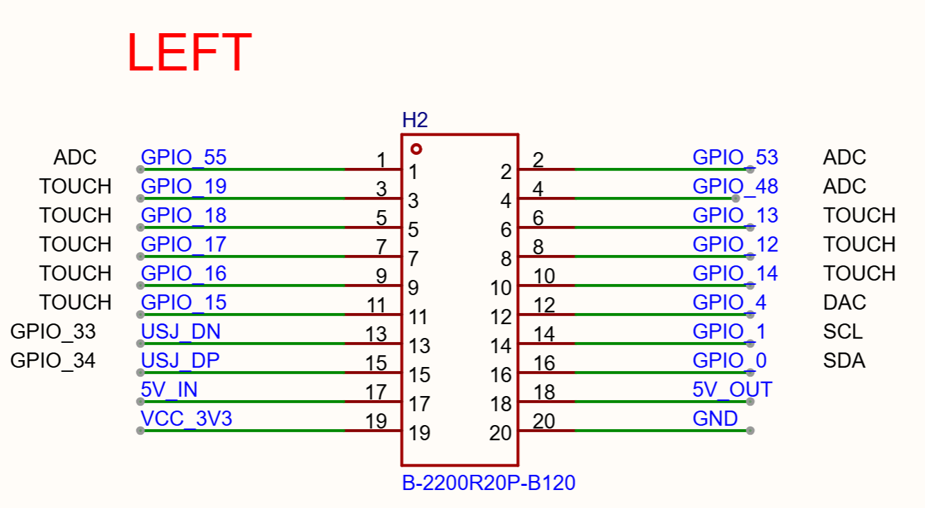
Left Module Interface Schematic (Click to enlarge)
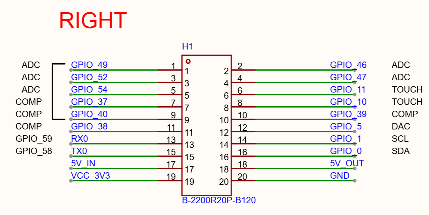
Right Module Interface Schematic (Click to enlarge)
Peripheral Notes
Photoresistor (LDR)
The GL5506 is sampled by ADC. The reading is shown as a 0–100 light percentage, which can indicate ambient brightness or drive LED intensity.
PIR Motion Sensor
The AS312 outputs a motion-detect level. When motion is detected, the corresponding status on the display lights up.
Infrared Transmit (IR)
The IR LED is driven by an AO3400A and sends NEC frames (8-bit address and command) at 38 kHz.
WS2812
The module has 6 WS2812 LEDs. Colors can be set individually or together, and the brightness can be limited.
Keys and Touch
KEY_L / KEY_R share the same pads and can be used as keys or touch:
Key: active when pressed to ground.
Touch: a finger on the pad triggers it, and pressing the key does as well.
Power
The module is powered from the host VCC_3V3 rail, which is output only when GPIO60 is driven low. On CoreBoard V1.2 the external 3.3 V rail is generated by a dedicated DCDC and is isolated from the internal MCU supply.
Hardware Revision Details
No previous versions.
Disclaimer and Copyright Notice
Please refer to the Disclaimer and Copyright Notice.