Connection
This document is the third tutorial in the Getting Started series on Bluetooth Low Energy (Bluetooth LE), aiming to provide a brief overview of the connection process. Subsequently, the tutorial introduces the code implementation of peripheral devices using the NimBLE_Connection example based on the NimBLE host layer stack.
Learning Objectives
Understand the basic concepts of connection
Learn about connection-related parameters
Explore the code structure of the NimBLE_Connection example
Basic Concepts
Initiating a Connection
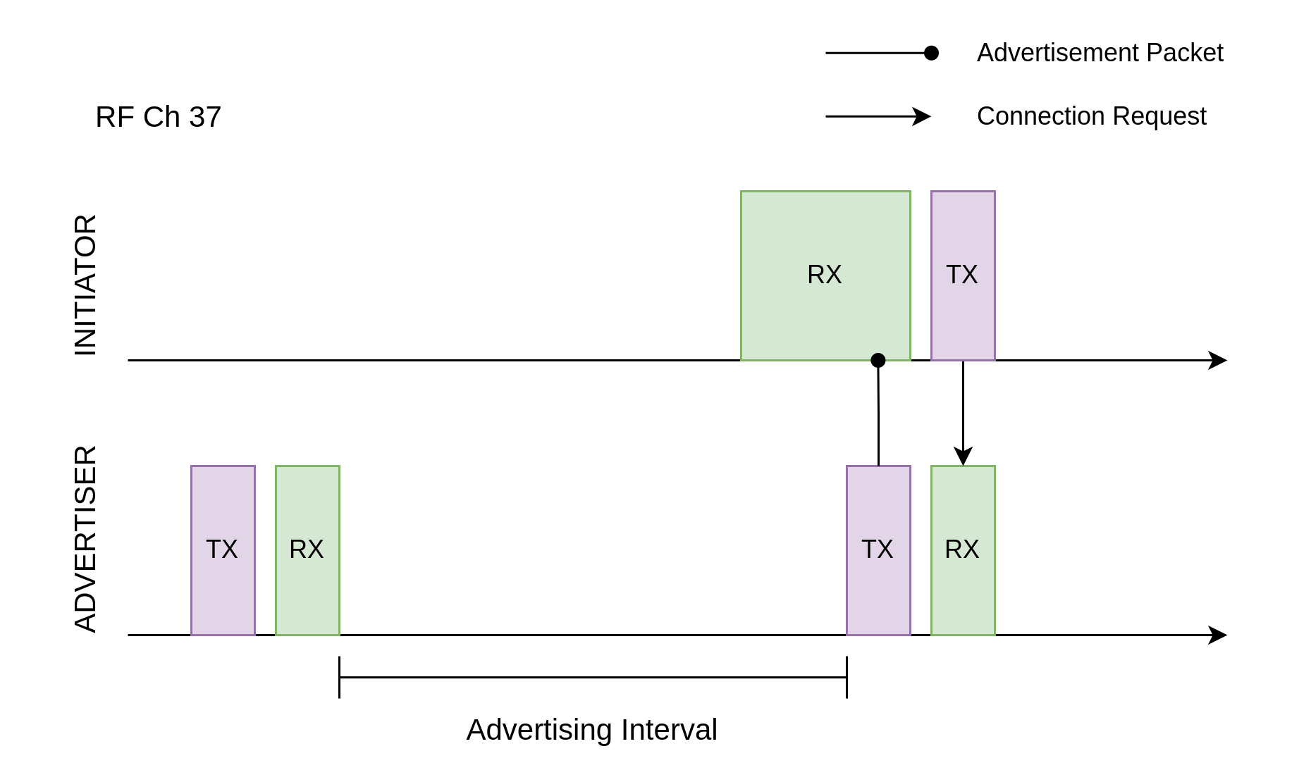
With the introduction of extended advertising features in Bluetooth LE 5.0, there are slight differences in the connection establishment process between Legacy ADV and Extended ADV. Below, we take the Legacy ADV connection establishment process as an example.
When a scanner receives an advertising packet on a specific advertising channel, if the advertiser is connectable, the scanner can send a connection request on the same advertising channel. The advertiser can set a Filter Accept List to filter out untrusted devices or accept connection requests from any scanner. Afterward, the advertiser becomes the peripheral device, and the scanner becomes the central device, allowing for bidirectional communication over the data channel.
As described in the section Scan Requests and Scan Responses, after each advertising period on a channel, the advertiser briefly enters RX mode to receive possible scan requests. In fact, this RX phase can also accept connection requests. Thus, for the scanner, the time window for sending a connection request is similar to that for sending a scan request.

Initiating a Connection
Connection Interval and Connection Event
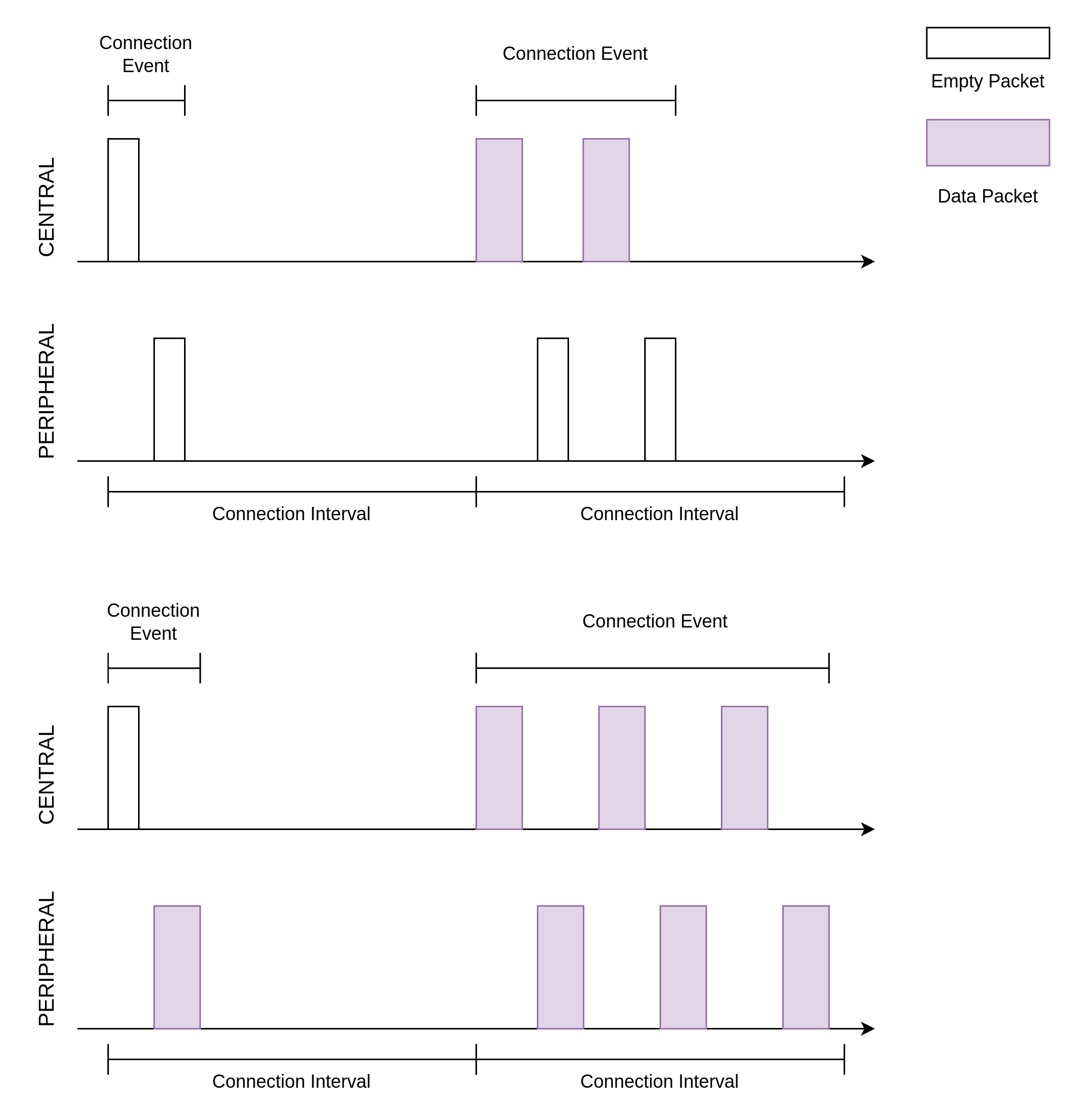
During a connection, the central and peripheral devices periodically exchange data, with this data exchange cycle referred to as the Connection Interval. The connection interval is one of the connection parameters determined during the initial connection request and can be modified afterward. The step size for the connection interval is 1.25 ms, with a range from 7.5 ms (6 steps) to 4.0 s (3200 steps).
A single data exchange process is termed Connection Event. During a connection event, there can be one or more data packet exchanges (when the data volume is large, it may need to be fragmented). In a data packet exchange, the central device first sends a packet to the peripheral device, followed by a packet from the peripheral device back to the central device. Even if either party does not need to send data at the start of a connection interval, it must send an empty packet to maintain the connection.
The timing relationship between the connection interval and connection event can be referenced in the diagram below.

Connection Interval and Connection Event
It's worth noting that if a connection event requires sending a large amount of data, causing the duration of the connection event to exceed the connection interval, the connection event must be split into multiple events. This means that if there isn't enough remaining time in the connection interval to complete the next packet exchange, the next packet exchange must wait until the next connection interval begins.
When the required data exchange frequency is low, a longer connection interval can be set; during the connection interval, the device can sleep outside of connection events to reduce power consumption.
Connection Parameters
As mentioned earlier, the connection interval is a connection parameter whose initial value is given by the central device in the connection request and can be modified in subsequent connections. In addition to the connection interval, there are many other important connection parameters. Below, we will explain some of these key parameters.
Supervision Timeout
Supervision Timeout defines the maximum time allowed between two successful connection events. If a successful connection event is followed by a period longer than the supervision timeout without another successful connection event, the connection is considered to be disconnected. This parameter is critical for maintaining connection status; for example, if one party unexpectedly loses power or moves out of range, the other party can determine whether to disconnect to conserve communication resources by checking for a timeout.
Peripheral Latency
Peripheral Latency specifies the maximum number of connection events that the peripheral device can skip when there is no data to send.
To understand the purpose of this parameter, consider a Bluetooth mouse as an example. When a user is typing on a keyboard, the mouse may not have any data to send, so it’s preferable to reduce the frequency of data packet transmissions to save power. Conversely, during mouse usage, we want the mouse to send data as quickly as possible to minimize latency. This means that the data transmission from the Bluetooth mouse is intermittently high-frequency. If we rely solely on the connection interval for adjustments, a lower connection interval would lead to high energy consumption, while a higher connection interval would result in high latency.
In this scenario, the peripheral latency mechanism is a perfect solution. To reduce the latency of a Bluetooth mouse, we can set a smaller connection interval, such as 10 ms, which allows a data exchange frequency of up to 100 Hz during intensive use. We can then set the peripheral latency to 100, allowing the mouse to effectively reduce the data exchange frequency to 1 Hz when idle. This design achieves variable data exchange frequency without adjusting connection parameters, maximizing user experience.
Maximum Transmission Unit
The Maximum Transmission Unit (MTU) refers to the maximum byte size of a single ATT data packet. Before discussing the MTU parameter, it's essential to describe the structure of the Data Channel Packet.
The structure of the Data Channel Packet is similar to that of the Advertising Packet, with differences in the PDU structure. The data PDU can be divided into three parts:
No. |
Name |
Byte Size |
Notes |
|---|---|---|---|
1 |
Header |
2 |
|
2 |
Payload |
0-27 / 0-251 |
Before Bluetooth LE 4.2, the maximum payload was 27 bytes; Bluetooth LE 4.2 introduced Data Length Extension (DLE), allowing a maximum payload of 251 bytes. |
3 |
Message Integrity Check, MIC |
4 |
Optional |
The payload of the data PDU can be further divided into:
No. |
Name |
Byte Size |
|---|---|---|
1 |
L2CAP Header |
4 |
2 |
ATT Header + ATT Data |
0-23 / 0-247 |
The default MTU value is 23 bytes, which matches the maximum ATT data byte size that can be carried in a single data PDU before Bluetooth LE 4.2.
MTU can be set to larger values, such as 140 bytes. Before Bluetooth LE 4.2, with a maximum of 23 bytes carrying ATT data in the payload, a complete ATT data packet would need to be split across multiple data PDUs. After Bluetooth LE 4.2, a single data PDU can carry up to 247 bytes of ATT data, so an MTU of 140 bytes can still be accommodated in a single data PDU.
Hands-On Practice
Having understood the concepts related to connections, let’s move on to the NimBLE_Connection example code to learn how to build a simple peripheral device using the NimBLE stack.
Prerequisites
An ESP32-C3 development board
ESP-IDF development environment
The nRF Connect for Mobile app installed on your phone
If you have not yet completed the ESP-IDF development environment setup, please refer to IDF Get Started.
Try It Out
Building and Flashing
The reference example for this tutorial is NimBLE_Connection .
You can navigate to the example directory using the following command:
$ cd <ESP-IDF Path>/examples/bluetooth/ble_get_started/nimble/NimBLE_Connection
Please replace <ESP-IDF Path> with your local ESP-IDF folder path. Then, you can open the NimBLE_Connection project using VSCode or another IDE you prefer. For example, after navigating to the example directory via the command line, you can open the project in VSCode using the following command:
$ code .
Next, enter the ESP-IDF environment in the command line and set the target chip:
$ idf.py set-target <chip-name>
You should see messages like:
...
-- Configuring done
-- Generating done
-- Build files have been written to ...
These messages indicate that the chip has been successfully configured. Then, connect the development board to your computer and run the following command to build the firmware, flash it to the board, and monitor the serial output from the ESP32-C3 development board:
$ idf.py flash monitor
You should see messages like:
...
main_task: Returned from app_main()
Wait until the notification ends.
Connect and Disconnect
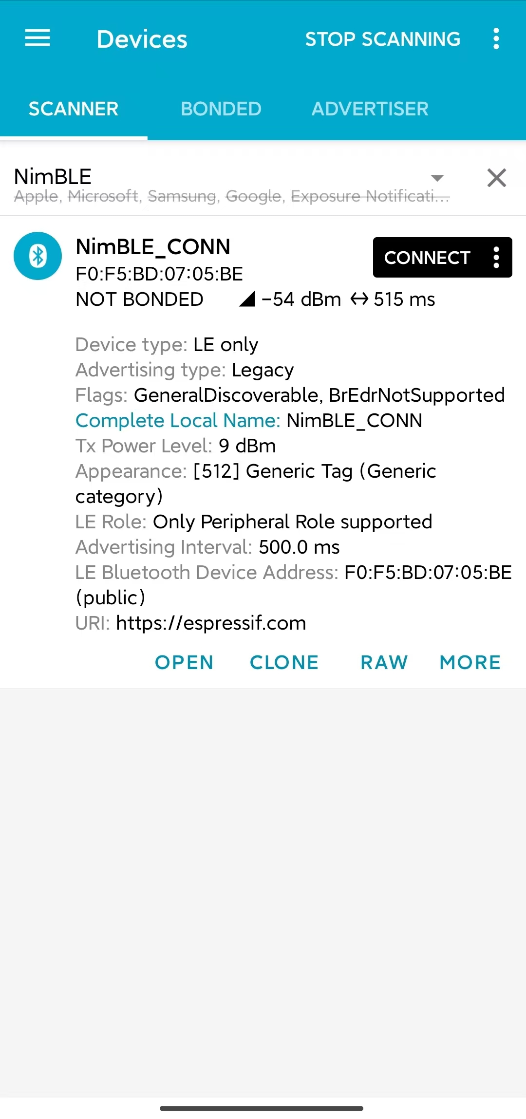
Open the nRF Connect for Mobile app on your phone, pull down to refresh in the SCANNER tab, and locate the NimBLE_CONN device as shown in the image below.

Locate NimBLE_CONN Device
If the device list is long, it's recommended to filter by the keyword "NimBLE" to quickly find the NimBLE_CONN device.
Compared to NimBLE_Beacon, you can observe that most of the advertising data is consistent, but there is an additional Advertising Interval data with a value of 500 ms. Below the CONNECT button, you should also see that the advertising interval is around 510 ms.
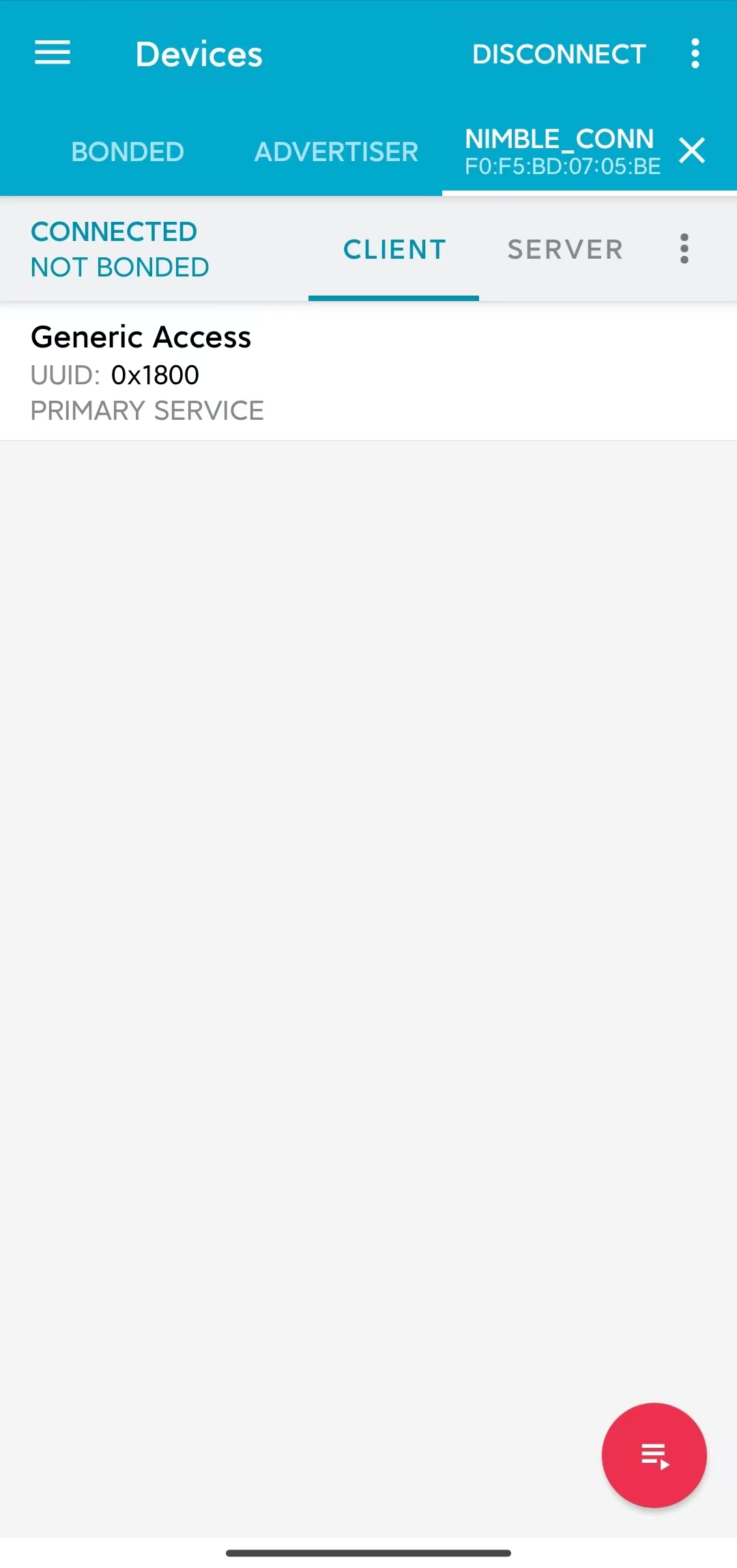
Click the CONNECT button to connect to the device, and you should be able to see the GAP service on your phone as shown below.

Connected to NimBLE_CONN Device
At this point, you should also see the LED on the development board light up. Click DISCONNECT to disconnect from the device, and the LED on the development board should turn off.
If your development board does not have any other LEDs except the one for the power indicator, you should be able to observe the corresponding status indicators in the log output.
Viewing Log Output
When connected to the device, you should see logs similar to the following:
I (36367) NimBLE_Connection: connection established; status=0
I (36367) NimBLE_Connection: connection handle: 0
I (36367) NimBLE_Connection: device id address: type=0, value=CE:4E:F7:F9:55:60
I (36377) NimBLE_Connection: peer id address: type=1, value=7F:BE:AD:66:6F:45
I (36377) NimBLE_Connection: conn_itvl=36, conn_latency=0, supervision_timeout=500, encrypted=0, authenticated=0, bonded=0

I (36397) NimBLE: GAP procedure initiated:
I (36397) NimBLE: connection parameter update; conn_handle=0 itvl_min=36 itvl_max=36 latency=3 supervision_timeout=500 min_ce_len=0 max_ce_len=0
I (36407) NimBLE:

I (37007) NimBLE_Connection: connection updated; status=0
I (37007) NimBLE_Connection: connection handle: 0
I (37007) NimBLE_Connection: device id address: type=0, value=CE:4E:F7:F9:55:60
I (37007) NimBLE_Connection: peer id address: type=1, value=7F:BE:AD:66:6F:45
I (37017) NimBLE_Connection: conn_itvl=36, conn_latency=3, supervision_timeout=500, encrypted=0, authenticated=0, bonded=0
The first part of the log shows the connection information output by the device when the connection is established, including the connection handle, the Bluetooth addresses of both the device and the mobile phone, as well as the connection parameters. Here, conn_itvl refers to the connection interval, conn_latency indicates the peripheral latency, and supervision_timeout is the connection timeout parameter. Other parameters can be temporarily ignored.
The second part indicates that the device initiated an update to the connection parameters, requesting to set the peripheral latency to 3.
The third part of the log displays the connection information after the update, showing that the peripheral latency has been successfully updated to 3, while other connection parameters remain unchanged.
When the device disconnects, you should see logs similar to the following:
I (63647) NimBLE_Connection: disconnected from peer; reason=531
I (63647) NimBLE: GAP procedure initiated: advertise;
I (63647) NimBLE: disc_mode=2
I (63647) NimBLE:  adv_channel_map=0 own_addr_type=0 adv_filter_policy=0 adv_itvl_min=800 adv_itvl_max=801
I (63657) NimBLE:

I (63657) NimBLE_Connection: advertising started!
You can observe that the device outputs the reason for disconnection when the connection is terminated, and then it initiates advertising again.
Code Details
Project Structure Overview
The root directory structure of NimBLE_Connection is identical to that of NimBLE_Beacon. However, after building the firmware, you may notice an additional managed_components directory in the root, which contains dependencies automatically included during firmware construction; in this case, it's the led_strip component used to control the development board's LED. This dependency is referenced in the main/idf_component.yml file.
Additionally, LED control-related source code has been introduced in the main folder.
Program Behavior Overview
The behavior of this example is mostly consistent with that of NimBLE_Beacon, with the key difference being that this example can accept scan requests from scanners and enter a connected state after entering advertising mode. Furthermore, it utilizes a callback function, gap_event_handler, to handle connection events and respond accordingly, such as turning on the LED when a connection is established and turning it off when the connection is terminated.
Entry Function
The entry function of this example is nearly the same as that of NimBLE_Beacon, except that before initializing NVS Flash, we call the led_init function to initialize the LED.
Starting Advertising
The process for initiating advertising is largely similar to that of NimBLE_Beacon, but there are some details to note.
First, we've added the advertising interval parameter in the scan response. We want to set the advertising interval to 500 ms, and since the unit for the advertising interval is 0.625 ms, we need to set it to 0x320. However, NimBLE provides a unit conversion macro BLE_GAP_ADV_ITVL_MS, which allows us to avoid manual calculations, as shown below:
static void start_advertising(void) {
    ...

    /* Set advertising interval */
    rsp_fields.adv_itvl = BLE_GAP_ADV_ITVL_MS(500);
    rsp_fields.adv_itvl_is_present = 1;

    ...
}
Next, we want the device to be connectable, so we need to modify the advertising mode from non-connectable to connectable. Additionally, the advertising interval parameter set in the scan response serves only to inform other devices and does not affect the actual advertising interval. This parameter must be set in the advertising parameter structure to take effect. Here, we set the minimum and maximum values of the advertising interval to 500 ms and 510 ms, respectively. Finally, we want to handle GAP events using the callback function gap_event_handler, so we pass this callback to the API ble_gap_adv_start that starts advertising. The relevant code is as follows:
static void start_advertising(void) {
    ...

    /* Set non-connetable and general discoverable mode to be a beacon */
    adv_params.conn_mode = BLE_GAP_CONN_MODE_UND;
    adv_params.disc_mode = BLE_GAP_DISC_MODE_GEN;

    /* Set advertising interval */
    adv_params.itvl_min = BLE_GAP_ADV_ITVL_MS(500);
    adv_params.itvl_max = BLE_GAP_ADV_ITVL_MS(510);

    /* Start advertising */
    rc = ble_gap_adv_start(own_addr_type, NULL, BLE_HS_FOREVER, &adv_params,
                        gap_event_handler, NULL);
    if (rc != 0) {
        ESP_LOGE(TAG, "failed to start advertising, error code: %d", rc);
        return;
    }
    ESP_LOGI(TAG, "advertising started!");

    ...
}
When the return value of ble_gap_adv_start is 0, it indicates that the device has successfully initiated advertising. Subsequently, the NimBLE protocol stack will call the gap_event_handler callback function whenever a GAP event is triggered, passing the corresponding GAP event.
GAP Event Handling
In this example, we handle three different types of GAP events:
Connection Event BLE_GAP_EVENT_CONNECT
Disconnection Event BLE_GAP_EVENT_DISCONNECT
Connection Update Event BLE_GAP_EVENT_CONN_UPDATE
The connection event is triggered when a connection is successfully established or when a connection attempt fails. If the connection fails, we will restart advertising. If the connection is successful, we will log the connection information, turn on the LED, and initiate a connection parameter update to set the peripheral latency parameter to 3. Here’s how the code looks:
static int gap_event_handler(struct ble_gap_event *event, void *arg) {
/* Local variables */
int rc = 0;
struct ble_gap_conn_desc desc;
/* Handle different GAP event */
switch (event->type) {
/* Connect event */
case BLE_GAP_EVENT_CONNECT:
/* A new connection was established or a connection attempt failed. */
ESP_LOGI(TAG, "connection %s; status=%d",
event->connect.status == 0 ? "established" : "failed",
event->connect.status);
/* Connection succeeded */
if (event->connect.status == 0) {
/* Check connection handle */
rc = ble_gap_conn_find(event->connect.conn_handle, &desc);
if (rc != 0) {
ESP_LOGE(TAG,
"failed to find connection by handle, error code: %d",
rc);
return rc;
}
/* Print connection descriptor and turn on the LED */
print_conn_desc(&desc);
led_on();
/* Try to update connection parameters */
struct ble_gap_upd_params params = {.itvl_min = desc.conn_itvl,
.itvl_max = desc.conn_itvl,
.latency = 3,
.supervision_timeout =
desc.supervision_timeout};
rc = ble_gap_update_params(event->connect.conn_handle, ¶ms);
if (rc != 0) {
ESP_LOGE(
TAG,
"failed to update connection parameters, error code: %d",
rc);
return rc;
}
}
/* Connection failed, restart advertising */
else {
start_advertising();
}
return rc;
...
}
return rc;
}
The disconnection event is triggered when either party disconnects from the connection. At this point, we log the reason for the disconnection, turn off the LED, and restart advertising. Here’s the code:
static int gap_event_handler(struct ble_gap_event *event, void *arg) {
    ...

    /* Disconnect event */
    case BLE_GAP_EVENT_DISCONNECT:
        /* A connection was terminated, print connection descriptor */
        ESP_LOGI(TAG, "disconnected from peer; reason=%d",
                event->disconnect.reason);

        /* Turn off the LED */
        led_off();

        /* Restart advertising */
        start_advertising();
        return rc;

    ...
}
The connection update event is triggered when the connection parameters are updated. At this point, we log the updated connection information. Here’s the code:
static int gap_event_handler(struct ble_gap_event *event, void *arg) {
    ...

    /* Connection parameters update event */
    case BLE_GAP_EVENT_CONN_UPDATE:
        /* The central has updated the connection parameters. */
        ESP_LOGI(TAG, "connection updated; status=%d",
                event->conn_update.status);

        /* Print connection descriptor */
        rc = ble_gap_conn_find(event->conn_update.conn_handle, &desc);
        if (rc != 0) {
            ESP_LOGE(TAG, "failed to find connection by handle, error code: %d",
                    rc);
            return rc;
        }
        print_conn_desc(&desc);
        return rc;

    ...
}
Summary
Through this tutorial, you have learned the basic concepts of connections and how to use the NimBLE host stack to build a Bluetooth LE peripheral device using the NimBLE_Connection example.
You can try to modify parameters in the example and observe the results in the log output. For instance, you can change the peripheral latency or connection timeout parameters to see if the modifications trigger connection update events.