Device Discovery
This document is the second tutorial in the Getting Started series on Bluetooth Low Energy (Bluetooth LE), aiming to provide a brief overview of the Bluetooth LE device discovery process, including basic concepts related to advertising and scanning. Following this, the tutorial introduces the code implementation of Bluetooth LE advertising, using the NimBLE_Beacon example based on the NimBLE host layer stack.
Learning Objectives
Understand the basic concepts of Advertising
Understand the basic concepts of Scanning
Learn about the code structure of the NimBLE_Beacon example
Advertising and Scanning are the states of Bluetooth LE devices during the device discovery phase before establishing a connection. First, let’s understand the basic concepts related to advertising.
Basic Concepts of Advertising
Advertising is the process where a device sends out advertising packets via its Bluetooth antenna. Since the advertiser does not know whether there is a receiver in the environment or when the receiver will activate its antenna, it needs to send advertising packets periodically until a device responds. During this process, there are several questions for the advertiser to consider:
Where should the advertising packets be sent? (Where?)
How long should the interval between advertising packets be? (When?)
What information should be included in the advertising packets? (What?)
Where to Send Advertising Packets?
Bluetooth Radio Frequency Band
The first question pertains to which radio frequency band the advertising packets should be sent on. The answer is provided by the Bluetooth Core Specification: the 2.4 GHz ISM band. This band is a globally available, license-free radio frequency band that is not controlled by any country for military or other purposes, and does not require payment to any organization. Thus, it has high availability and no usage costs. However, this also means the 2.4 GHz ISM band is very crowded and may interfere with other wireless communication protocols such as 2.4 GHz WiFi.
Bluetooth Channels
Similar to Bluetooth Classic, the Bluetooth SIG has adopted Adaptive Frequency Hopping (AFH) in Bluetooth LE to address data collision issues. This technology can assess the congestion of RF channels and avoid crowded channels through frequency hopping to improve communication quality. However, unlike Bluetooth Classic, Bluetooth LE uses the 2.4 GHz ISM band divided into 40 RF channels, each with a 2 MHz bandwidth, ranging from 2402 MHz to 2480 MHz, while Bluetooth Classic uses 79 RF channels, each with a 1 MHz bandwidth.
In the Bluetooth LE 4.2 standard, RF channels are categorized into two types, as follows:
Type |
Quantity |
Index |
Purpose |
|---|---|---|---|
Advertising Channel |
3 |
37-39 |
Used for sending advertising packets and scan response packets |
Data Channel |
37 |
0-36 |
Used for sending data channel packets |
During advertising, the advertiser will send advertising packets on the three advertising channels (37-39). Once the advertising packets have been sent on all three channels, the advertising process is considered complete, and the advertiser will repeat the process at the next advertising interval.
Extended Advertising Features
In the Bluetooth LE 4.2 standard, advertising packets are limited to a maximum of 31 bytes, which restricts the functionality of advertising. To enhance the capability of advertising, Bluetooth 5.0 introduced the Extended Advertising feature. This feature divides advertising packets into:
Type |
Abbreviation |
Max Payload Size per Packet (Bytes) |
Max Total Payload Size (Bytes) |
|---|---|---|---|
Primary Advertising Packet |
Legacy ADV |
31 |
31 |
Extended Advertising Packet |
Extended ADV |
254 |
1650 |
Extended advertising packets are composed of ADV_EXT_IND and AUX_ADV_IND, transmitted on the primary and secondary advertising channels, respectively. The primary advertising channels correspond to channels 37-39, while the secondary advertising channels correspond to channels 0-36. Since the receiver always receives advertising data on the primary advertising channels, the advertiser must send ADV_EXT_IND on the primary advertising channels and AUX_ADV_IND on the secondary advertising channels. ADV_EXT_IND will indicate the secondary advertising channels where AUX_ADV_IND is transmitted. This mechanism allows the receiver to obtain the complete extended advertising packet by first receiving ADV_EXT_IND on the primary advertising channels and then going to the specified secondary advertising channels to receive AUX_ADV_IND.
Type |
Channels |
Purpose |
|---|---|---|
Primary Advertising Channel |
37-39 |
Used to transmit ADV_EXT_IND of the extended advertising packet |
Secondary Advertising Channel |
0-36 |
Used to transmit AUX_ADV_IND of the extended advertising packet |
How long should the advertising interval be?
Advertising Interval
For the second question, regarding the period for sending advertising packets, the Bluetooth standard provides a clear parameter definition: Advertising Interval. The advertising interval can range from 20 ms to 10.24 s, with a step size of 0.625 ms.
The choice of advertising interval affects both the discoverability of the advertiser and the device’s power consumption. If the advertising interval is too long, the probability of the advertising packets being received by a receiver becomes very low, which decreases the advertiser’s discoverability. Conversely, if the advertising interval is too short, frequent advertising consumes more power. Therefore, the advertiser needs to balance between discoverability and power consumption and choose the most appropriate advertising interval based on the application's needs.
It is worth noting that if there are two advertisers with the same advertising interval in the same space, packet collision may occur, meaning both advertisers are sending advertising data to the same channel at the same time. Since advertising is a one-way process with no reception, the advertiser cannot know if a packet collision has occurred. To reduce the likelihood of such collisions, advertisers should add a random delay of 0-10 ms after each advertising event.
What information is included in the advertising packet?
Advertising Packet Structure
For the third question, regarding the information contained in the advertising packet, the Bluetooth LE 4.2 standard defines the format of the advertising packet, as shown in the diagram below:
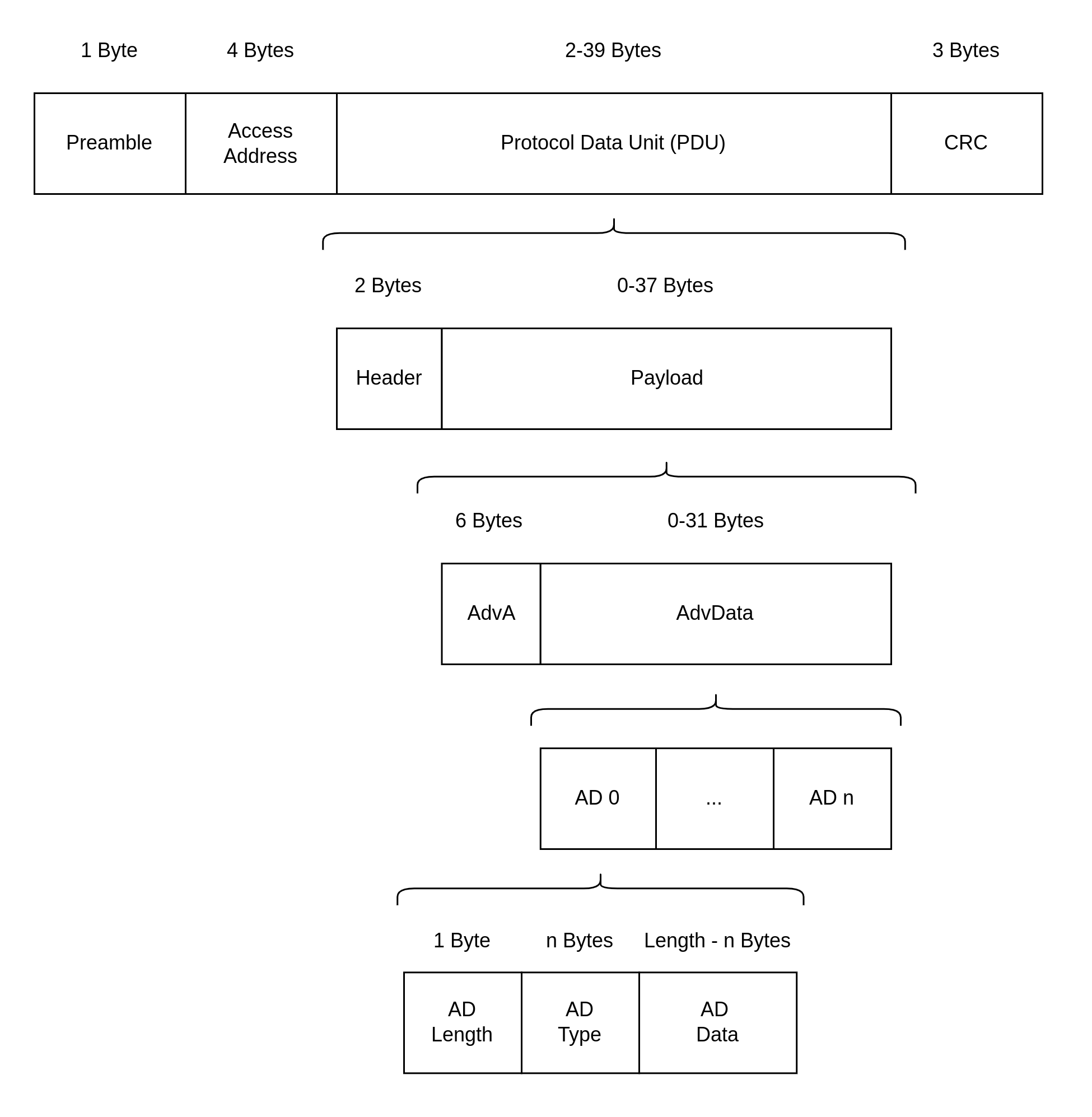
Bluetooth LE 4.2 Advertising Packet Structure
Let’s break it down step by step. The outer layer of an advertising packet contains four parts, which are:
No. |
Name |
Byte Size |
Function |
|---|---|---|---|
1 |
Preamble |
1 |
A special bit sequence used for device clock synchronization |
2 |
Access Address |
4 |
Marks the address of the advertising packet |
3 |
Protocol Data Unit, PDU |
2-39 |
The area where the actual data is stored |
4 |
Cyclic Redundancy Check, CRC |
3 |
Used for cyclic redundancy checking |
The advertising packet is a type of Bluetooth packet, and its nature is determined by the type of PDU. Now, let's take a detailed look at the PDU.
PDU
The PDU segment is where the actual data is stored. Its structure is as follows:
No. |
Name |
Byte Size |
|---|---|---|
1 |
Header |
2 |
2 |
Payload |
0-37 |
PDU Header
The PDU header contains various pieces of information, which can be broken down into six parts:
No. |
Name |
Bit Size |
Notes |
|---|---|---|---|
1 |
PDU Type |
4 |
|
2 |
Reserved for Future Use, RFU |
1 |
|
3 |
Channel Selection Bit, ChSel |
1 |
Indicates whether the advertiser supports the LE Channel Selection Algorithm #2 |
4 |
TX Address, TxAdd |
1 |
0/1 indicates Public Address/Random Address |
5 |
Rx Address, RxAdd |
1 |
0/1 indicates Public Address/Random Address |
6 |
Payload Length |
8 |
The PDU Type bit reflects the advertising behavior of the device. In the Bluetooth protocol, there are three pairs of advertising behaviors:
- Connectable vs. Non-connectable:
Whether the device accepts connection requests from others.
- Scannable vs. Non-scannable:
Whether the device accepts scan requests from others.
- Undirected vs. Directed:
Whether the advertising packet is sent to a specific device.
These advertising behaviors can be combined into four common types of advertising, corresponding to four different PDU types:
Connectable? |
Scannable? |
Undirected? |
PDU Type |
Purpose |
|---|---|---|---|---|
Y |
Y |
Y |
ADV_IND |
The most common advertising type |
Y |
N |
N |
ADV_DIRECT_IND |
Commonly used for reconnecting with known devices |
N |
N |
Y |
ADV_NONCONN_IND |
Used by beacon devices to advertising data without connection |
N |
Y |
Y |
ADV_SCAN_IND |
Used by beacons to advertise additional data via a scan response when packet length is insufficient |
PDU Payload
The PDU Payload is divided into two parts:
No. |
Name |
Byte Size |
Notes |
|---|---|---|---|
1 |
Advertisement Address, AdvA |
6 |
The 48-bit Bluetooth address of the advertiser |
2 |
Advertisement Data, AdvData |
0-31 |
Consists of multiple Advertisement Data Structures |
The Advertisement Address can be either a:
Type |
Description |
|---|---|
Public Address |
A globally unique fixed device address that manufacturers must register and pay fees to IEEE for |
Random Address |
A randomly generated address |
Random addresses are further divided into two categories:
Type |
Description |
|---|---|
Random Static Address |
Can be either fixed in firmware or randomly generated at startup but must not change during operation. Often used as an alternative to a Public Address. |
Random Private Address |
Periodically changes to prevent device tracking. |
For devices using random private addresses to communicate with trusted devices, an Identity Resolving Key (IRK) should be used to generate the random address. Devices with the same IRK can resolve and obtain the true address. There are two types of random private addresses:
Type |
Description |
|---|---|
Resolvable Random Private Address |
Can be resolved with an IRK to obtain the device’s true address |
Non-resolvable Random Private Address |
Completely random and rarely used, as it cannot be resolved and is only meant to prevent tracking |
Let's look at the advertising data. The format of an advertising data structure is defined as follows:
No. |
Name |
Byte Size |
Notes |
|---|---|---|---|
1 |
AD Length |
1 |
|
2 |
AD Type |
n |
Most types take 1 byte |
3 |
AD Data |
(AD Length - n) |
Basic Concepts of Scanning
Similar to the advertising process, scanning also raises three questions:
Where to scan? (Where?)
When to scan and for how long? (When?)
What to do during scanning? (What?)
For Bluetooth LE 4.2 devices, the advertiser only sends data on the advertising channels, which are channels 37-39. For Bluetooth LE 5.0 devices, if the advertiser has enabled extended advertising, it sends ADV_EXT_IND on the primary advertising channels and AUX_ADV_IND on the secondary advertising channels. Thus, for Bluetooth LE 4.2 devices, scanners only need to receive advertising data on advertising channels. For Bluetooth LE 5.0 devices, scanners must first receive the ADV_EXT_IND on the primary advertising channels and, if it indicates a secondary channel, move to the corresponding secondary channel to receive the AUX_ADV_IND.
Scan Window and Scan Interval
The second question refers to the concepts of the Scan Window and the Scan Interval.
Scan Window: the duration for which the scanner continuously receives packets on a single RF channel. For example, if the scan window is set to 50 ms, the scanner continuously scans for 50 ms on each RF channel.
Scan Interval: the time between the start of two consecutive scan windows, which means the scan interval is always greater than or equal to the scan window.
The diagram below illustrates the process of a scanner receiving advertising packets on a timeline. The scanner's scan interval is 100 ms, and the scan window is 50 ms; the advertiser's advertising interval is 50 ms, and the duration of the advertising packet transmission is for illustrative purposes only. As shown, the first scan window corresponds to channel 37, where the scanner successfully receives the advertiser's first broadcasting packet sent on channel 37, and this pattern continues.
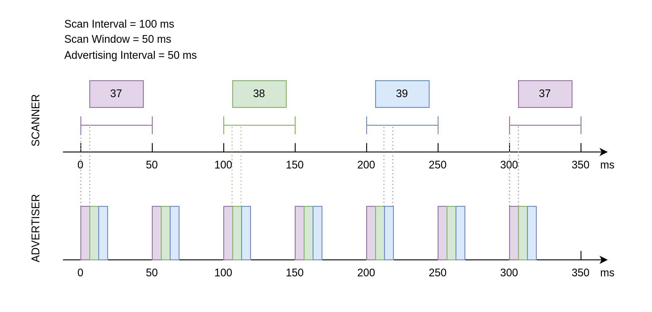
Advertising and Scanning Timing Diagram
Scan Request and Scan Response
From the current introduction, it might seem that the advertiser only transmits and the scanner only receives during the advertising process. However, scanning behavior is divided into two types:
- Passive Scanning:
The scanner only receives advertising packets.
- Active Scanning:
After receiving an advertising packet, the scanner sends a scan request to a scannable advertiser.
When a scannable advertiser receives a scan request, it sends a scan response packet, providing more advertising information to the interested scanner. The structure of the scan response packet is identical to the advertising packet, with the difference being the PDU type in the PDU header.
In scenarios where the advertiser operates in scannable advertising mode and the scanner in active scanning mode, the data transmission timing between the advertiser and the scanner becomes more complex. For the scanner, after a scan window ends, it briefly switches to TX mode to send a scan request, then quickly switches back to RX mode to receive a possible scan response. For the advertiser, after each advertising, it briefly switches to RX mode to receive any scan requests, and upon receiving one, it switches to TX mode to send the scan response.
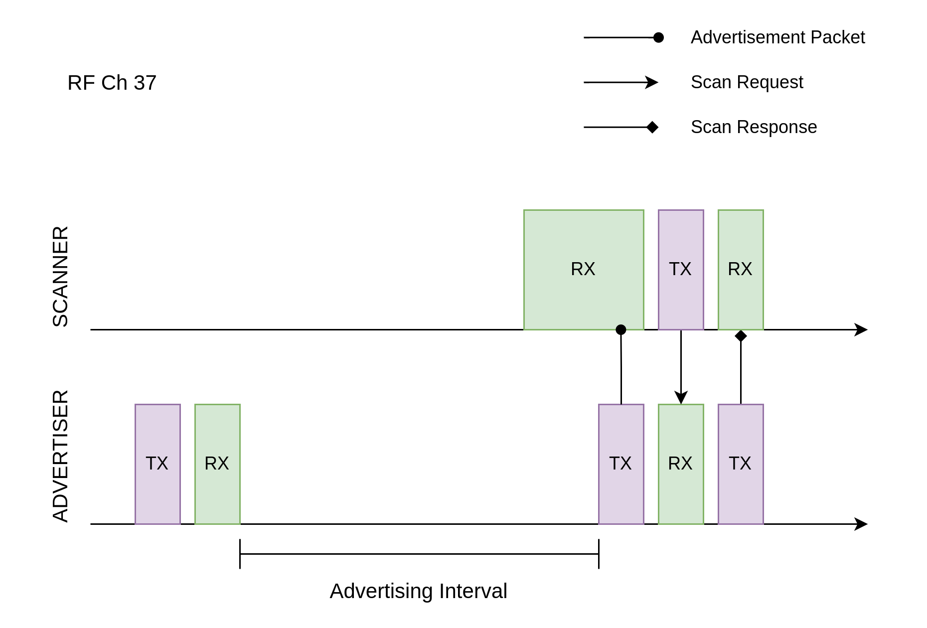
Scan Request Reception and Scan Response Transmission
Hands-On Practice
After learning the relevant concepts of advertising and scanning, let's apply this knowledge in practice using the NimBLE_Beacon example to create a simple beacon device.
Prerequisites
An ESP32-H2 development board
ESP-IDF development environment
The nRF Connect for Mobile app installed on your phone
If you haven't set up the ESP-IDF development environment yet, please refer to IDF Get Started.
Try It Out
Building and Flashing
The reference example for this tutorial is NimBLE_Beacon .
You can navigate to the example directory using the following command:
$ cd <ESP-IDF Path>/examples/bluetooth/ble_get_started/nimble/NimBLE_Beacon
Please replace <ESP-IDF Path> with your local ESP-IDF folder path. Then, you can open the NimBLE_Beacon project using VSCode or another IDE you prefer. For example, after navigating to the example directory via the command line, you can open the project in VSCode using the following command:
$ code .
Next, enter the ESP-IDF environment in the command line and set the target chip:
$ idf.py set-target <chip-name>
You should see messages like:
...
-- Configuring done
-- Generating done
-- Build files have been written to ...
These messages indicate that the chip has been successfully configured. Then, connect the development board to your computer and run the following command to build the firmware, flash it to the board, and monitor the serial output from the ESP32-H2 development board:
$ idf.py flash monitor
You should see messages like:
...
main_task: Returned from app_main()
Wait until the notification ends.
Viewing Beacon Device Information
Open the nRF Connect for Mobile app on your phone, go to the SCANNER tab, and pull down to refresh. Locate the NimBLE_Beacon device, as shown in the figure below.
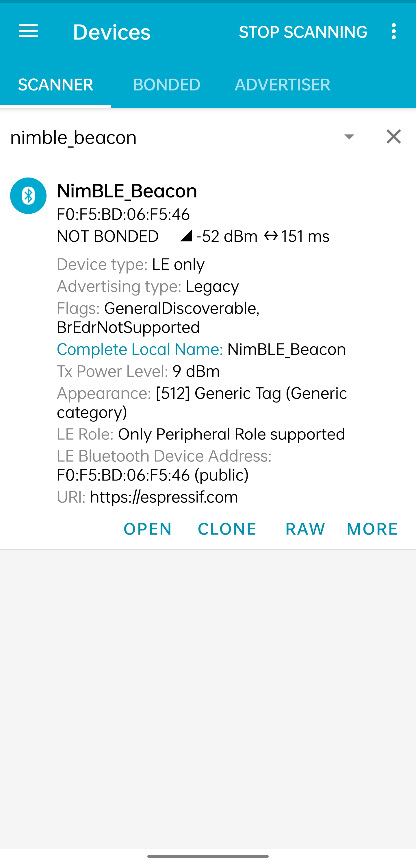
Locate NimBLE Beacon Device
If the device list is long, it is recommended to filter by the keyword NimBLE in the device name to quickly find the NimBLE_Beacon device.
You will notice that the NimBLE Beacon device contains rich information, including the Espressif website (this demonstrates the beacon advertising feature). Click the RAW button in the lower-right corner to view the raw advertising packet data, as shown below.
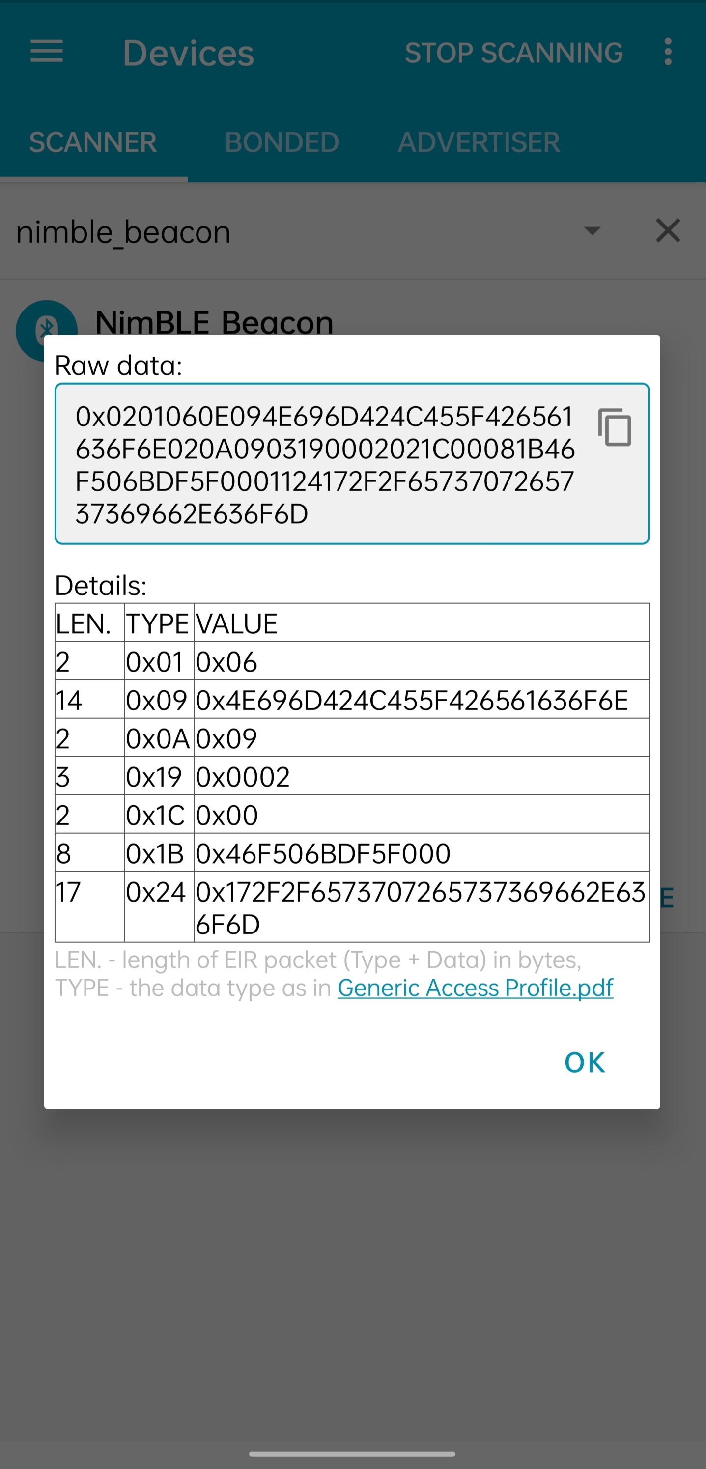
Advertising Packet Raw Data
Details table summarizes all advertising data structures in the advertising data packet and the scan response data packet:
Name |
Length |
Type |
Raw Data |
Resolved Information |
|---|---|---|---|---|
Flags |
2 Bytes |
0x01 |
0x06 |
General Discoverable, BR/EDR Not Supported |
Complete Local Device Name |
14 Bytes |
0x09 |
0x4E696D424C455F426561636F6E |
NimBLE_Beacon |
TX Power Level |
2 Bytes |
0x0A |
0x09 |
9 dBm |
Appearance |
3 Bytes |
0x19 |
0x0002 |
Generic Tag (Generic category) |
LE Role |
2 Bytes |
0x1C |
0x00 |
Only Peripheral Role supported |
LE Bluetooth Device Address |
8 Bytes |
0x1B |
0x46F506BDF5F000 |
F0:F5:BD:06:F5:46 |
URI |
17 Bytes |
0x24 |
0x172F2F6573707265737369662E636F6D |
https://espressif.com |
It is worth mentioning that the total length of the first five advertising data structures is 28 bytes, leaving only 3 bytes of space in the advertising data packet, which is not enough to accommodate the last two data structures. Therefore, the last two advertising data structures must be placed in the scan response data packet.
You may also notice that the Raw Data for the Device Appearance is 0x0002, while in the code, the definition for Generic Tag is 0x0200. Additionally, the Raw Data for the Device Address appears to be completely reversed, except for the last byte (0x00). This is because Bluetooth LE air packets follow a little-endian transmission order, meaning the lower bytes are placed at the front.
Also, note that the nRF Connect for Mobile app does not provide a CONNECT button to connect to this device, which aligns with our expectations since a Beacon device is inherently non-connectable. Now, let's dive into the code details to see how such a Beacon device is implemented.
Code Explanation
Project Structure Overview
The root directory of NimBLE_Beacon is roughly divided into the following parts:
- README*.md
Documentation for the project
- sdkconfig.defaults*
Default configurations for different chip development boards
- CMakeLists.txt
Used to include the ESP-IDF build environment
- main
The main project folder containing the source code, header files, and build configurations
Program Behavior Overview
Before diving into the code details, let's first get a macro understanding of the program behavior.
First, we initialize the various modules used in the program, mainly including NVS Flash, the NimBLE Host Stack, and the GAP service.
After the NimBLE Host Stack synchronizes with the Bluetooth controller, we confirm the Bluetooth address is available, then initiate an undirected, non-connectable, and scannable advertisement.
The device remains in advertising mode continuously until a reboot occurs.
Entry Function
As with other projects, the entry function of the application is the app_main function in the main/main.c file, where we typically initialize the modules. In this example, we mainly do the following:
Initialize NVS Flash and the NimBLE Host Stack
Initialize the GAP service
Start the FreeRTOS task for the NimBLE Host Stack
The ESP32-H2 Bluetooth stack uses NVS Flash to store related configurations, so before initializing the Bluetooth stack, we must call the nvs_flash_init API to initialize NVS Flash. In some cases, we may need to call the nvs_flash_erase API to erase NVS Flash before initialization.
void app_main(void) {
    ...

    /* NVS flash initialization */
    ret = nvs_flash_init();
    if (ret == ESP_ERR_NVS_NO_FREE_PAGES ||
        ret == ESP_ERR_NVS_NEW_VERSION_FOUND) {
        ESP_ERROR_CHECK(nvs_flash_erase());
        ret = nvs_flash_init();
    }
    if (ret != ESP_OK) {
        ESP_LOGE(TAG, "failed to initialize nvs flash, error code: %d ", ret);
        return;
    }

    ...
}
Next, you can call nimble_port_init API to initialize NimBLE host stack.
void app_main(void) {
    ...

    /* NimBLE host stack initialization */
    ret = nimble_port_init();
    if (ret != ESP_OK) {
        ESP_LOGE(TAG, "failed to initialize nimble stack, error code: %d ",
                ret);
        return;
    }

    ...
}
Then, we call the gap_init function defined in the gap.c file to initialize the GAP service and set the device name and appearance.
void app_main(void) {
    ...

    /* GAP service initialization */
    rc = gap_init();
    if (rc != 0) {
        ESP_LOGE(TAG, "failed to initialize GAP service, error code: %d", rc);
        return;
    }

    ...
}
Next, we configure the NimBLE host stack, which mainly involves setting some callback functions, including callbacks for when the stack is reset and when synchronization is complete, and then saving the configuration.
static void nimble_host_config_init(void) {
    /* Set host callbacks */
    ble_hs_cfg.reset_cb = on_stack_reset;
    ble_hs_cfg.sync_cb = on_stack_sync;
    ble_hs_cfg.store_status_cb = ble_store_util_status_rr;

    /* Store host configuration */
    ble_store_config_init();
}

void app_main(void) {
    ...

    /* NimBLE host configuration initialization */
    nimble_host_config_init();

    ...
}
Finally, start the FreeRTOS thread for the NimBLE host stack.
static void nimble_host_task(void *param) {
    /* Task entry log */
    ESP_LOGI(TAG, "nimble host task has been started!");

    /* This function won't return until nimble_port_stop() is executed */
    nimble_port_run();

    /* Clean up at exit */
    vTaskDelete(NULL);
}

void app_main(void) {
    ...

    /* Start NimBLE host task thread and return */
    xTaskCreate(nimble_host_task, "NimBLE Host", 4*1024, NULL, 5, NULL);

    ...
}
Start Advertising
When developing applications using the NimBLE host stack, the programming model is event-driven.
For example, after the NimBLE host stack synchronizes with the Bluetooth controller, a synchronization completion event will be triggered, invoking the ble_hs_cfg.sync_cb function. When setting up the callback function, we point the function pointer to the on_stack_sync function, which is the actual function called upon synchronization completion.
In the on_stack_sync function, we call the adv_init function to initialize advertising operations. In adv_init, we first call the ble_hs_util_ensure_addr API to confirm that a usable Bluetooth address is available. Then, we call the ble_hs_id_infer_auto API to obtain the optimal Bluetooth address type.
static void on_stack_sync(void) {
    /* On stack sync, do advertising initialization */
    adv_init();
}

void adv_init(void) {
    ...

    /* Make sure we have proper BT identity address set */
    rc = ble_hs_util_ensure_addr(0);
    if (rc != 0) {
        ESP_LOGE(TAG, "device does not have any available bt address!");
        return;
    }

    /* Figure out BT address to use while advertising */
    rc = ble_hs_id_infer_auto(0, &own_addr_type);
    if (rc != 0) {
        ESP_LOGE(TAG, "failed to infer address type, error code: %d", rc);
        return;
    }

    ...
}
Next, we copy the Bluetooth address data from the NimBLE stack's memory space into the local addr_val array, preparing it for subsequent use.
void adv_init(void) {
    ...

    /* Copy device address to addr_val */
    rc = ble_hs_id_copy_addr(own_addr_type, addr_val, NULL);
    if (rc != 0) {
        ESP_LOGE(TAG, "failed to copy device address, error code: %d", rc);
        return;
    }
    format_addr(addr_str, addr_val);
    ESP_LOGI(TAG, "device address: %s", addr_str);

    ...
}
Finally, we call the start_advertising function to initiate advertising. Within the start_advertising function, we first populate the advertising data structures, including the advertising flags, complete device name, transmission power level, device appearance, and LE role, into the advertising packet as follows:
static void start_advertising(void) {
    /* Local variables */
    int rc = 0;
    const char *name;
    struct ble_hs_adv_fields adv_fields = {0};

    ...

    /* Set advertising flags */
    adv_fields.flags = BLE_HS_ADV_F_DISC_GEN | BLE_HS_ADV_F_BREDR_UNSUP;

    /* Set device name */
    name = ble_svc_gap_device_name();
    adv_fields.name = (uint8_t *)name;
    adv_fields.name_len = strlen(name);
    adv_fields.name_is_complete = 1;

    /* Set device tx power */
    adv_fields.tx_pwr_lvl = BLE_HS_ADV_TX_PWR_LVL_AUTO;
    adv_fields.tx_pwr_lvl_is_present = 1;

    /* Set device appearance */
    adv_fields.appearance = BLE_GAP_APPEARANCE_GENERIC_TAG;
    adv_fields.appearance_is_present = 1;

    /* Set device LE role */
    adv_fields.le_role = BLE_GAP_LE_ROLE_PERIPHERAL;
    adv_fields.le_role_is_present = 1;

    /* Set advertiement fields */
    rc = ble_gap_adv_set_fields(&adv_fields);
    if (rc != 0) {
        ESP_LOGE(TAG, "failed to set advertising data, error code: %d", rc);
        return;
    }

    ...
}
The ble_hs_adv_fields structure predefines some commonly used advertising data types. After completing the data setup, we can enable the corresponding advertising data structures by setting the relevant is_present field to 1 or by assigning a non-zero value to the corresponding length field (len). For example, in the code above, we configure the device's transmission power with adv_fields.tx_pwr_lvl = BLE_HS_ADV_TX_PWR_LVL_AUTO;, and then enable that advertising data structure by setting adv_fields.tx_pwr_lvl_is_present = 1;. If we only configure the transmission power without setting the corresponding is_present field, the advertising data structure becomes invalid. Similarly, we configure the device name with adv_fields.name = (uint8_t *)name; and set the name's length with adv_fields.name_len = strlen(name); to add the device name as an advertising data structure to the advertising packet. If we only configure the device name without specifying its length, the advertising data structure will also be invalid.
Finally, we call the ble_gap_adv_set_fields API to finalize the setup of the advertising data structures in the advertising packet.
In the same way, we can fill in the device address and URI into the scan response packet as follows:
static void start_advertising(void) {
    ...

    struct ble_hs_adv_fields rsp_fields = {0};

    ...

    /* Set device address */
    rsp_fields.device_addr = addr_val;
    rsp_fields.device_addr_type = own_addr_type;
    rsp_fields.device_addr_is_present = 1;

    /* Set URI */
    rsp_fields.uri = esp_uri;
    rsp_fields.uri_len = sizeof(esp_uri);

    /* Set scan response fields */
    rc = ble_gap_adv_rsp_set_fields(&rsp_fields);
    if (rc != 0) {
        ESP_LOGE(TAG, "failed to set scan response data, error code: %d", rc);
        return;
    }

    ...
}
Finally, we set the advertising parameters and initiate the advertising by calling the ble_gap_adv_start API.
static void start_advertising(void) {
    ...

    struct ble_gap_adv_params adv_params = {0};

    ...

    /* Set non-connetable and general discoverable mode to be a beacon */
    adv_params.conn_mode = BLE_GAP_CONN_MODE_NON;
    adv_params.disc_mode = BLE_GAP_DISC_MODE_GEN;

    /* Start advertising */
    rc = ble_gap_adv_start(own_addr_type, NULL, BLE_HS_FOREVER, &adv_params,
                        NULL, NULL);
    if (rc != 0) {
        ESP_LOGE(TAG, "failed to start advertising, error code: %d", rc);
        return;
    }
    ESP_LOGI(TAG, "advertising started!");
}
Summary
Through this tutorial, you have learned the basic concepts of advertising and scanning, and you mastered the method of building a Bluetooth LE Beacon device using the NimBLE host stack through the NimBLE_Beacon example.
You can try to modify the data in the example and observe the changes in the nRF Connect for Mobile app. For instance, you might modify the adv_fields or rsp_fields structures to change the populated advertising data structures, or swap the advertising data structures between the advertising packet and the scan response packet. However, keep in mind that the maximum size for the advertising data in both the advertising packet and the scan response packet is 31 bytes; if the size of the advertising data structure exceeds this limit, calling the ble_gap_adv_start API will fail.